
EECE 442 Homework, Spring 2008
American University of Beirut · Communication Systems · 10 pages


More EECE 442 files
Show the text of this homework
LECE444 Hsmusrrk 3 SxloTan iro
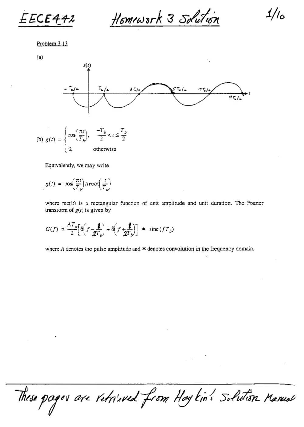
Problem 3.13
fa)
0, otherwise
Equivalently, we may write
f
att) = cos} (mt) |Arect|
ri
\T,/ \Ty
where rect(t) is a rectangular function of unit amplitude and unit duration. The Fourier
transiorm of g(7) is given by
GY) = Sar, f- 4) +5 (745) * sinc(fT,)
where A denotes the pulse amplitude and * denotes convolution in the frequency domain.
These Py” aye Kobievede Za Hag bin Sladen. Pleniatl
Using the replication property of the delta function 5(/), we get
Gf) = SF sine rf 7) +me(7{s+7))]
Using Eq. (1.52) of the textbook, the power spectral density of the binary data stream is
Ion
T,
S(f)
4
apf sine { Tf - 7)) + sinc (nls + 7)
| -#2sine( Ty f- 2) sine (r{r+ 7) o
, .
‘Note that the two spectral components sine( 7, f- 2 ) and sine( 7, ft 7)) overlap in
u
F
the frequency interval -(1/T,) < f < (I/T;), hence the presence of cross-product terms in Eq.
(1).
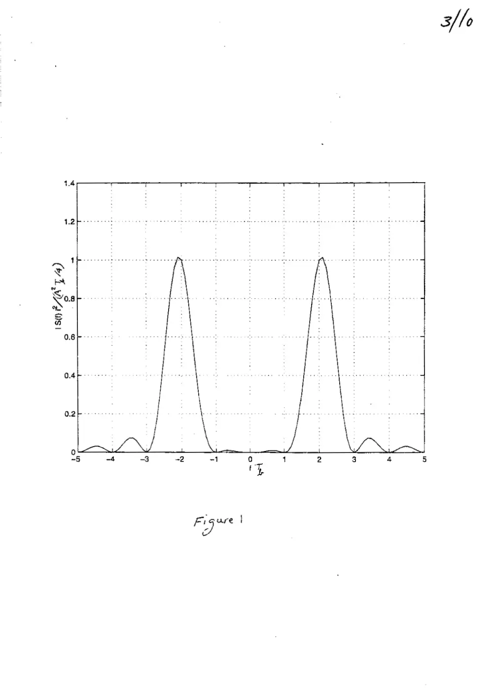
Figure | plots the normalized power spectral density S(PKAP7T,/4) versus the normalized
frequency fT. The interesting point to note in this figure is the significant reduction in the
power spectrum of the pulse-shaped data stream x(r) in the interval -1/T, <f< 1/7;
(c) The power spectral density of the standard form of polar NRZ signaling is
S(f) = A’Tysine (fT) (2)
Comparing this expression with that of Eq. (1), we observe the following differences:
Polar NRZ signals using Polar NRZ signals using
cosine pulses rectangular pulses
f=0 A’T,
f= UT, A’T,/4 9
3/10
1.4 —<— ——~
oO
CARAT
Co)
: i
eeec al eseedae ve : +
: : : : t
L J 1 n L 1 io
x ~ Q- © < x 4
e So f=) fo]
fem 3.2
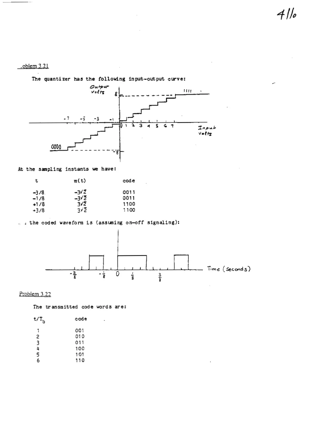
The quantizer has the following input-output curve:
Outpur
volts
At the sampling instants we have:
t
3/8.
-1/8
41/8
+3/8
a the coded waveform is (assuming on-off signaling):
Problem 3.22
m(t)
<3V2
~342
372
372
aie Se eee ne
|
ttre
cade
0011
0011
1100
1100
2
8
4
8
0
'
8
The transmitted code words are:
t/T,
AU fw a=
code
001
0710
014
100
101
110
3
g
Time (Seconds)
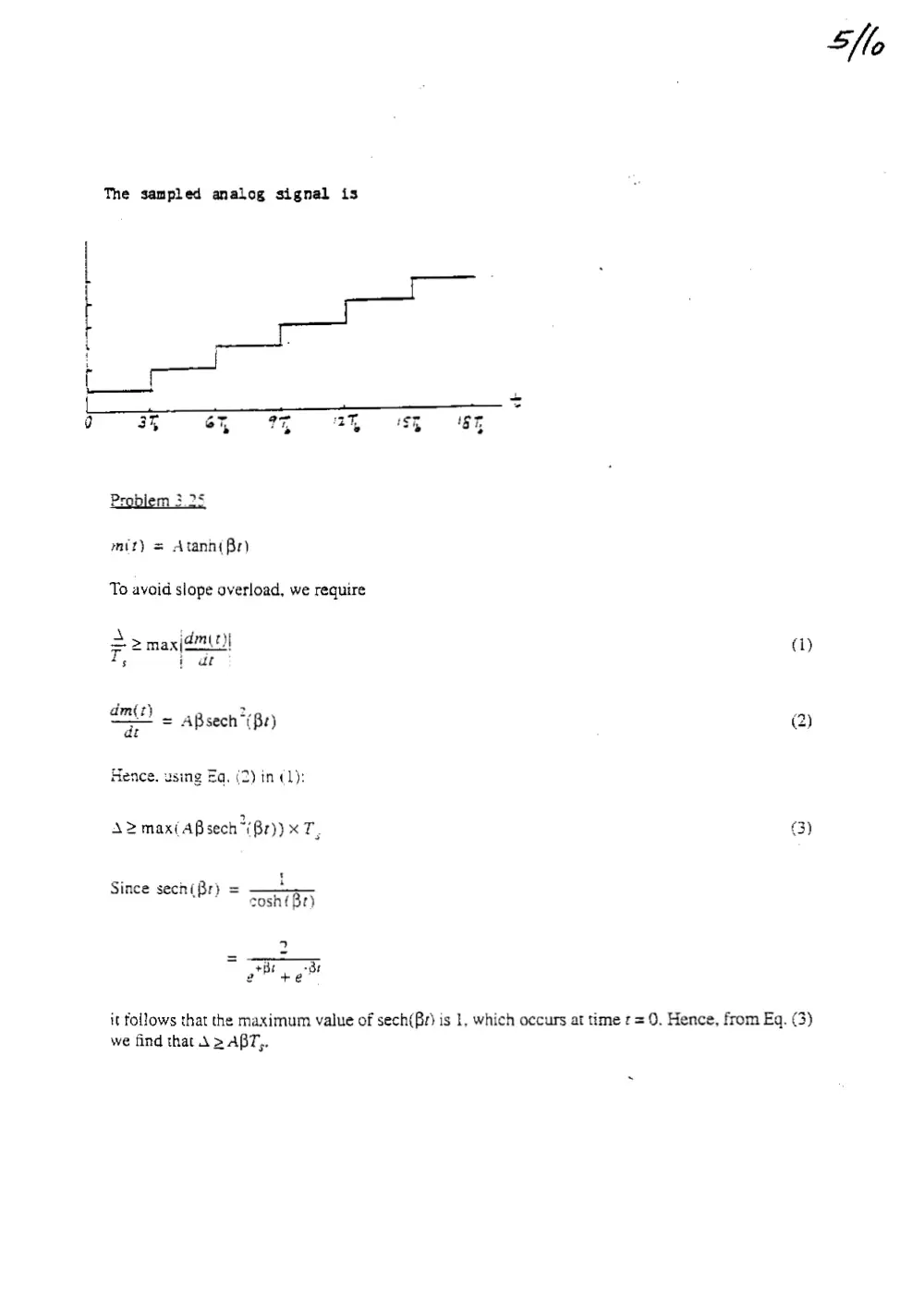
The sampled analog signal is
—— .
a 3% 6% O9T 27% 8B ET
Problem 3.25
mit) = Atann{ Br)
To avoid siope overload, we require
a> max|72)! qa)
T, i ae:
dm(t 2, ;
mit) ABsech (Br) (2)
dt
Hence. using Eq. (2) in (1):
A2max(ABsech {82)) xT, (3)
i
Since sech( Br} = ——.—
Br sosh{ Br)
2
ot Bt +e or
it follows that the maximum value of sech(Br) is 1. which occurs at time r= 0. Hence, from Eq. (3)
we find that A > ABT,.
flo
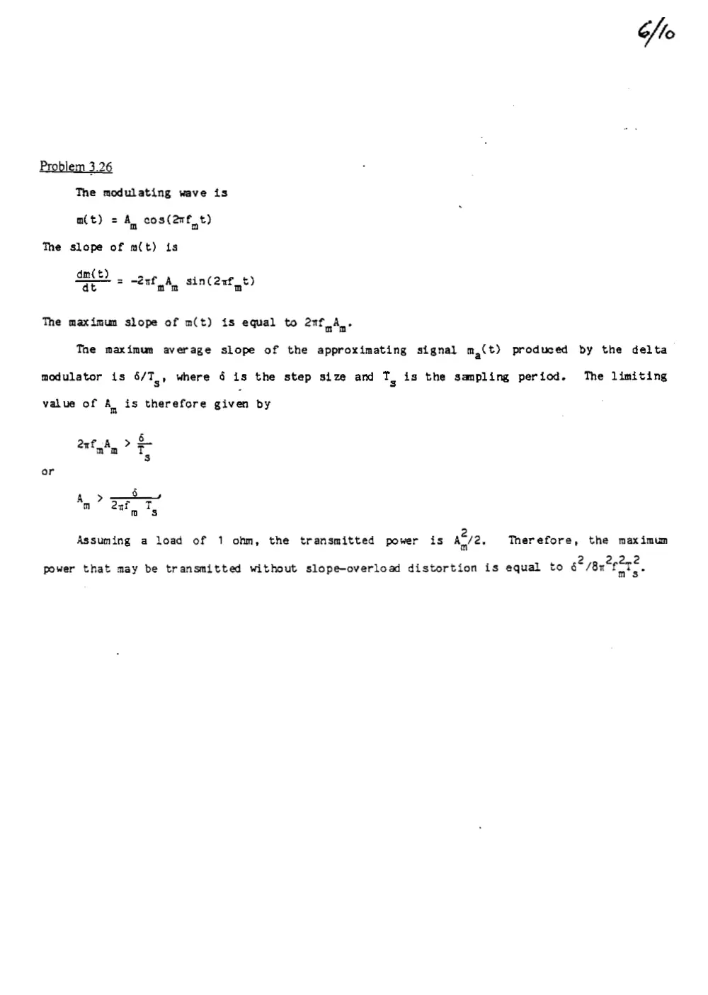
Problem 3.26
The modulating wave is
mt) = An eos(2nf t)
The slope of m{t) is
dm(t)
dt
= Went AL sin¢ anf t)
The maximum slope of m(t) is equal to ant Ane
Tne maximum average slope of the approximating signal m,(t) produced by the delta
modulator is 8/T. where 6 is the step size and TS is the sampling period. The limiting
value of a is therefore given by
6
ent a T
or
Assuming a load of 1 ohm, the transmitted power is a2, Therefore, the maximum
. ‘ 2 pg Cplme
power that may be transmitted without slope-overload distortion is equal to 6 18x fas?
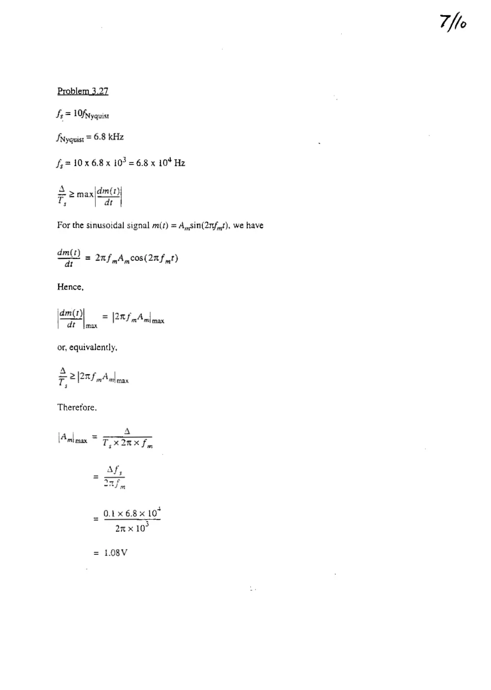
Problem 3.27
fs = L0fNyquist
Fxyquist = 6.8 kHz
f,=10x6.8x 10? =6.8 x 10* Hz
A jdm(t)
—2>
F 2 max)
For the sinuscidal signal m(t) = A,,sin(27f,,7), we have
a
m(t)
a? 20 f pAmCOS(2Tf pt)
Hence,
jdm(t - :
| A Mo 7 [PFS nA max
or, equivalently,
A
77 PRs A
m | max
Therefore.
i) ue A
\Anlmax = FX Inx f,
_ Af;
~ Ae
oni in
_ OLX 6.8 x 10"
2n x 10°
1.08V
7M
Tits Steg Fes gS RRR SMG cong oe do atte Deke fiche garding yore oe pot TR
“fo
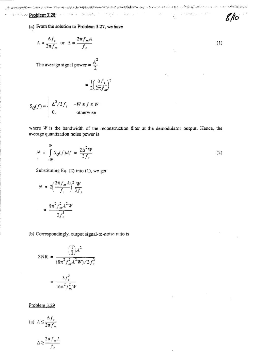
(a) From the solution to Problem 3.27, we have
_ Af, _ 2nf A 1
A oF. or A= F, ; ())
1
2
So(f) = A’/3 f, —-W<fsw
‘ 0, otherwise
where W is the bandwidth of the reconstruction filter at the demodulator output. Hence, the
average quantization noise power is
wv “
._ 2aW ~
N= J Soifar = SO 2)
: -w
Substituting Eq. (2) into (1), we get
SNR
A> ZXRX 10> x1
50 x 10°
= 0.126V
(b) (SNR)... =
out 16x f
>
16x"
= 475
In decibels,
(SNR)oy, = 1Olog 9475
= 26.8 dB
Problem 3.30
(a) For linear delta modulation, the maximum amplitude of a sinusoidal test signal that can be
Cmte
3. (30x 10°)"
Xe
10° x5x 10
used without slope-overload distortion is
0.1 x 60x 10°
2mx ix 10°
0.95V
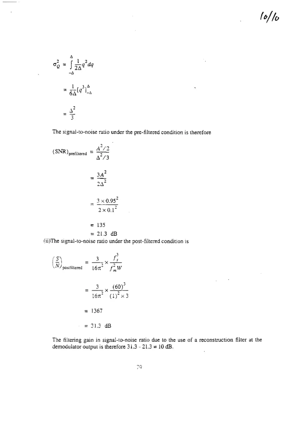
(b) (1) Under the pre-filtered condition, it is reasonable to assume that the granular quantization
noise is uniformiy distributed between -A and +A. Hence, the variance of the quantization
noise is
f, = 2x3xi0x/9
ho
wa
A
3
The signai-to-noise ratio under the pre-filtered condition is therefore
(SNR)
(ii)The signal-to-noise ratio under the post-filtered condition is
f S)
\N) postfiltered
prefiltered =
Hl
i
lt
= 135
= 21.3 dB
2
3 f;
fnW
lon
3. (60)
3 2
lén” (1)°x3
1367
31.3 dB
fol fo
The filtering gain in signal-to-noise ratio due to the use of a reconstruction filter at the
demodulator output is therefore 31.3 - 21.3 = 10 dB.