
EECE 442 Homework, Spring 2008
American University of Beirut · Communication Systems · 18 pages





Showing the first 10 of 18 pages. Download the PDF to see all of it.
More EECE 442 files
Show the text of this homework
EECE (4-44 PAS A Pr / 1S
Problem 4.1
(a) The impulse response of the matched filter is
h(t) = s(T-t)
The s(t) and h(t) are shown below:
s(t)
A/2
t
n(t)
t
(b) The corresponding output of the matched filter is obtained by convolving h(t) with
s(t). The result is shown below:
s_(t)
°
WE
Problem 4.2
(a) The matched filter of impulse response /,(t) for pulse s)(z) is given in the solution to Problem
4.1. The matched filter of impulse response />(z) for s2(r) is given by
Ay = 5,(T-1)
which has the following waveform:
Apt)
AR fr--
3714
0 Ti T smd
-A/2 4
Fig. 1
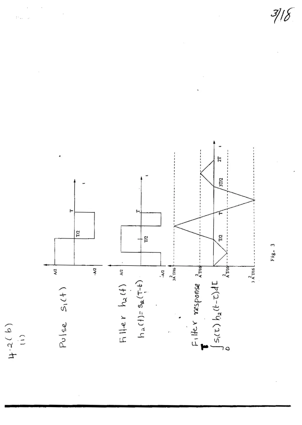
(b} (i) The response of the matched filter, matched to s2(r) and due to s,(t) as input, is obtained by
convolving f(t) with sy(z), as shown by
aT
Y(t) = 5, 34(T)Ag(t —T)dt
The waveform of the output y2;{t) so computed is plotted in Figure 2. This figure also
includes the corresponding waveforms of input s;(¢) and impulse response A(t).
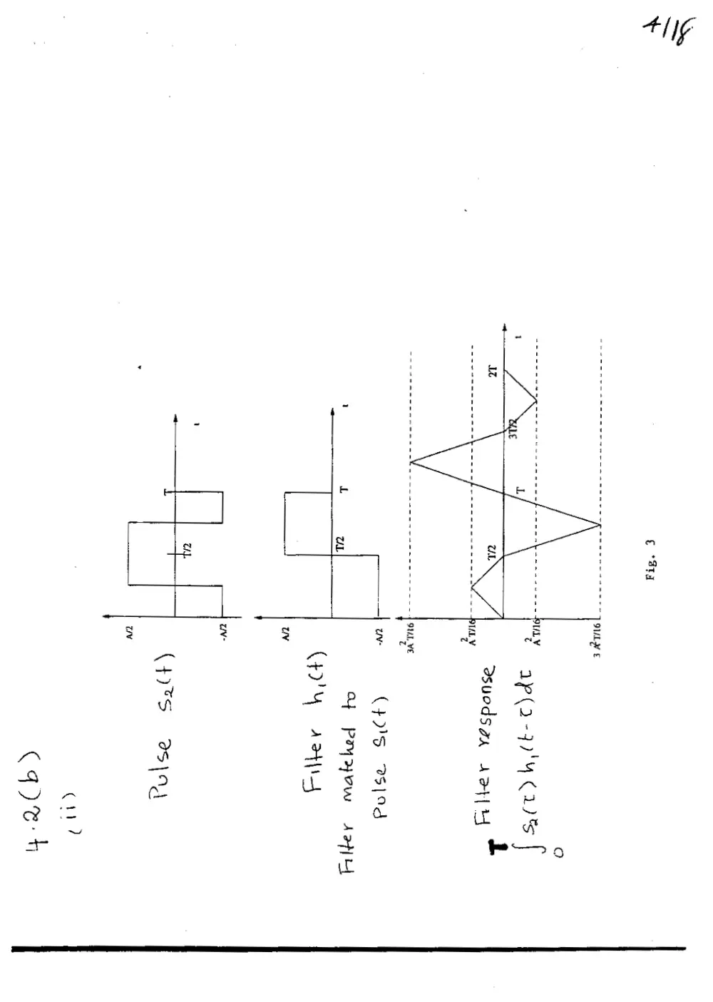
(ii) Next, the response of the matched filter, matched to s)(#) and due to s(t) as input, is
obtained by convolving /;(t) with 52(1), as shown by
a
Yt) = {say —t)dt
Figure 3 shows the waveforms of input s2(¢), impulse response /,(#), and response y(t).
€ 'S14
SUL V €
.
OWL VE
z
uv:
TL a
; t—7A—7 (Gat) es =(F"Y
a I (pry artyy
UL
L
(47's Bs\ad
Ch)
(gq pen
] 9ULy €
esucdss, vay]
TAL V
4
SUAL WE
z
—|~ (45 2sI19d
Of Pyar sano
(py arts
uy
ci?
Cqyeh
SI
Note that y)2(f) is exactly the negative of y2;(t). However, in both cases we find that att =
T, both outputs are equal to zero, as shown by
Yoi(T) = yi2(T) = 0
For n pulses s)(t) $9(¢),...,8,(¢) that are orthogonal to each other over the interval [0,T], the
n-dimensional matched filter has the following structure:
Filter matched
>—- to s\(t) Output |
Filter matched —
}-—_—j—-——__—_}
to 54(t) Output 2
input
| Filter matched
to s,(t)
Fig. 4
Problem 4.4
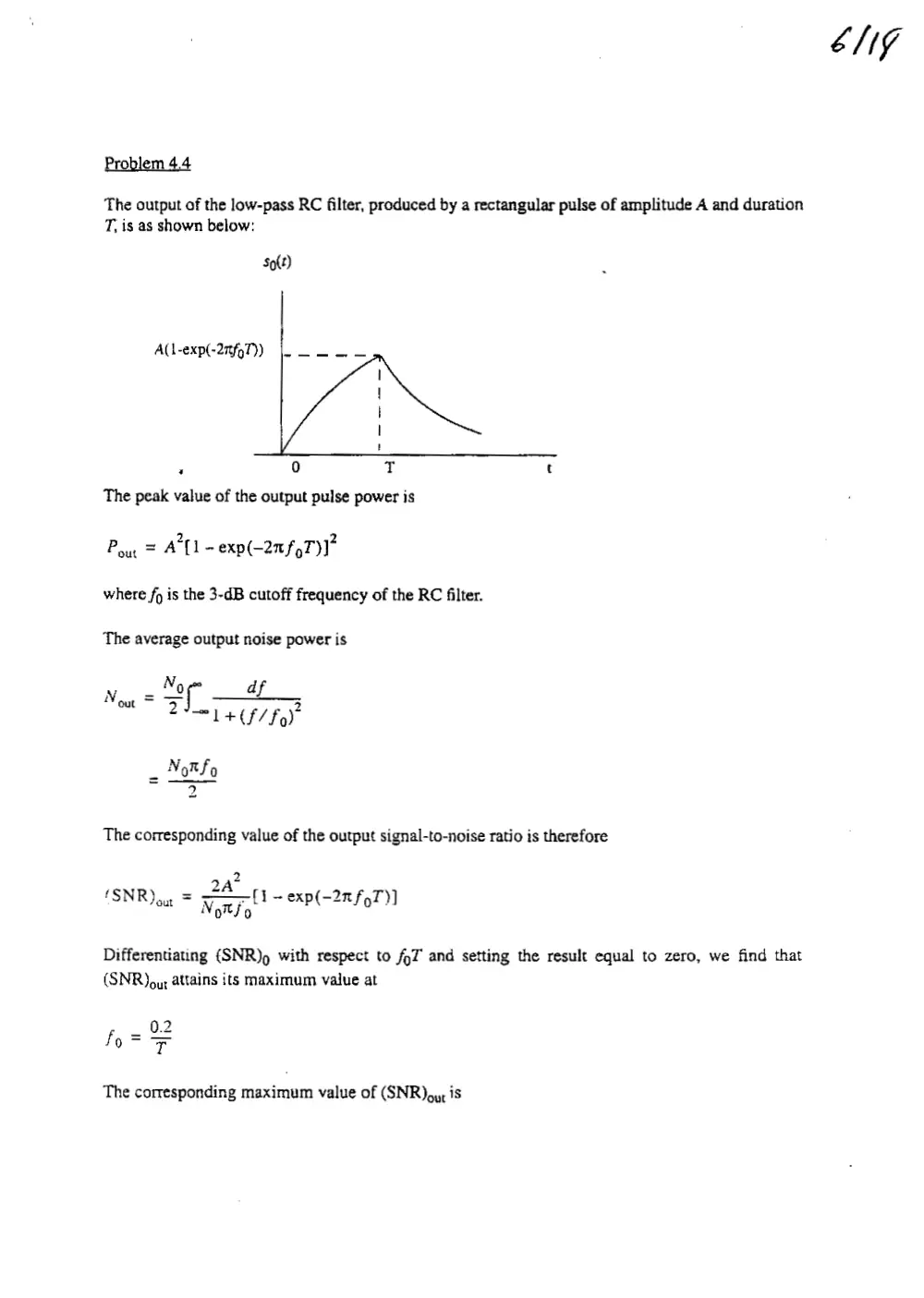
The output of the low-pass RC filter, produced by a rectangular pulse of amplitude A and duration
T, is as shown below:
So(t)
A(1-exp(-27f97))
a
The peak value of the output pulse power is
2
Poy = A [1 -exp(-2afoT)]"
where fp is the 3-dB cutoff frequency of the RC filter.
The average output noise power is
Noe ap
err
. Not fa
a)
The corresponding value of the output signal-to-noise ratio is therefore
2
(SNR) out - inl a 7 oxp(2nfot)]
Differentiating (SNR)p with respect to fo7 and setting the result equal to zero, we find that
(SNR)oy; attains its maximum value at
0.
foar
is)
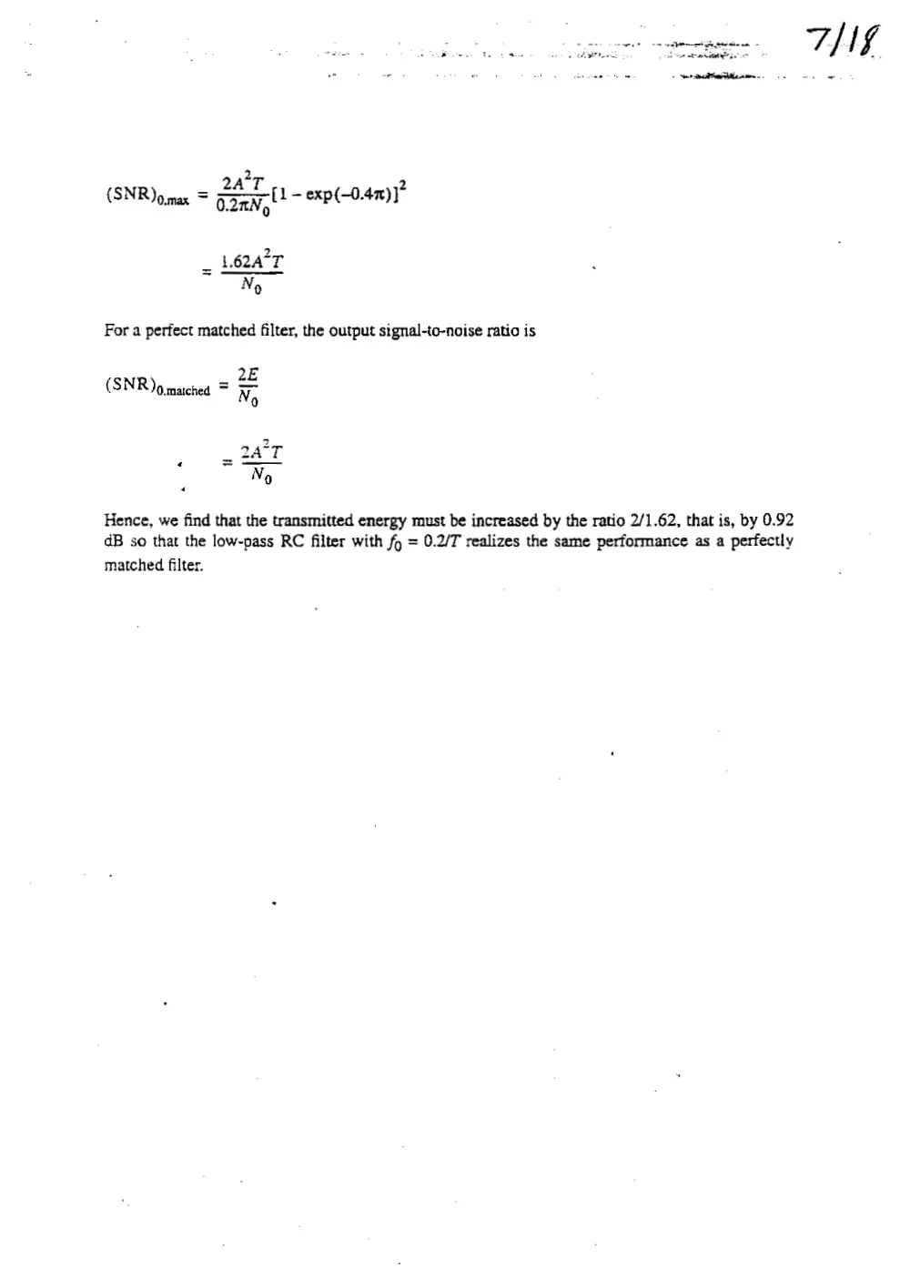
The corresponding maximum value of (SNR)oy, is
ENG
2a°T
2
dav, - exp(—0.47)]}
(SNR) gynax =
_ 1.62A°T
No
For a perfect matched filter, the output signal-to-noise ratio is
2E
(SNR )omached = FF
0
2
2A T
No
4
Hence, we find that the transmitted energy must be increased by the ratio 2/1.62, that is, by 0.92
dB so that the low-pass RC filter with fo = 0.2/T realizes the same performance as a perfectly
matched filter.
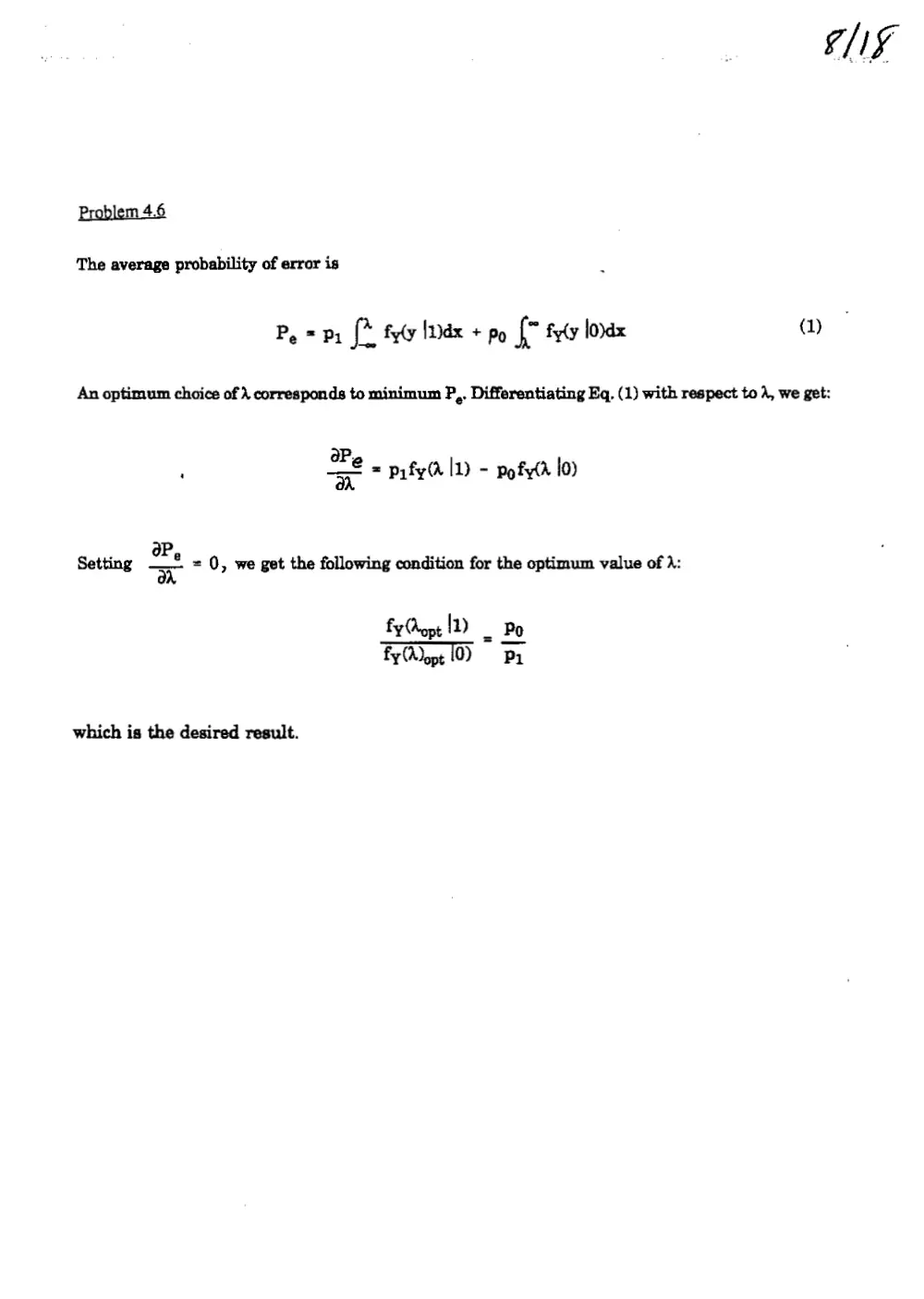
Problem 4.6
The average probability of error is
P, = pr {* fyly Idx + po f* fyly lorax a)
An optimum choice of 4 corresponds to minimum P,. Differentiating Eq. (1) with respect to 4, we get:
ap,
, =" = pyfy(0 11) - pofy(d 10)
oP
Setting x = 0, we get the following condition for the optimum value of 1:
fy opt 1) _ Po
fy opt 10) Pi
which is the desired result.
NS
roblem 4.7
In a binary PCM system, with NRZ signaling, the average probability of error is
P, z erft ae
The signal energy per bit is
Ey = AT,
where A is the pulse amplitude and T,, is the bit (pulse) duration. If the signaling rate is doubled,
the bit duration T, is reduced by half. Correspondingly, E, is reduced by half.
Let u = LE Np- We may then set
P, = 10° = $ erfe(u)
Solving for u, we get
u = 3.3
When the signaling rate is doubled, the new value of P, is
= ; erfc(2.33)
1073.
loli
Problem 4.8
(a) The average probability of error is
where E,, = AT, We may rewrite this formula as
‘ P, = i orf] (1)
2 o
where A is the pulse amplitude at o = WNT, We may view o” as playing the role of noise variance
at the decision device input. Let
E
u- (2 -A
No fos
We are given that
o =/0- volts?, o = 0.1 volt
P, = 107%
Since P, is quite small, we may approximate it as follows:
erfe(u) = 2xp(-u)
yru