
EECE 471 Final, Fall 2003
American University of Beirut · Fundamentals of Power Systems Analysis · 6 pages · Prof. Sami Karaki



More EECE 471 files
- Final · Summer 2010Final examView
- Final Solution · Summer 2010Final exam · with solutionView
- Final · Fall 2008Final examView
- Final Solution · Fall 2008Final exam · with solutionView
- Final · Fall 2007Final examView
- Final Solution · Fall 2007Final exam · with solutionView
- Final · Fall 2005Final examView
- Final Solution · Fall 2005Final exam · with solutionView
Show the text of this final exam
S. KARAKI
AMERICAN UNIVERSITY OF BEIRUT
FALL 2003/ 2004
FACULTY OF ENGINEERING AND ARCHITECTURE
FINAL EXAM
POWER SYSTEMS FUNDAMENTALS (EECE 471)
CLOSED BOOK (3 HOURS)
January 29, 2004
FIRST READ CAREFULLY THE QUESTION SHEET AND THEN START:
�
PROGRAMMABLE CALCULATORS ARE NOT ALLOWED.
�
THIS QUESTION SHEET MUST BE RETURNED WITH THE ANSWER BOOKLET.
�
BRIEFLY EXPLAIN CALCULATIONS BY SHOWING FORMULAE OR OTHERWISE AS
NEEDED.
�
ON YOUR ANSWER BOOKLET, USE THE RECTO FOR ANSWER AND THE VERSO FOR
SCRATCH
NAME: _________________________
ID#: _________________________
1. Consider the following power system shown in Fig. 1 below. The load will be
modeled as a constant impedance load taking 32+j16 MVA at nominal voltage.
The given percent impedances are with respect to corresponding equipment
rating. For this exercise calculations are to be done with SB= 10 MVA.
13.2kV
50 MVA
XG= 120%
Load
Y-∆
G
∆-Y
13.2:66kV
50 MVA
XT1= 12%
66:11kV
40 MVA
XT2= 12%
0.08+j0.4 Ω/ km
3
4
2
1
80 km
Fig. 1: 4-Node System for Problem 1.
a) Calculate the load impedance in ohms.
b) Select the generator rated voltage as a base voltage on generator side. What
should be the base voltages on the transmission and load sides? What are base
impedances on the generator, transmission, and load sides?
c) Draw an impedance diagram showing the generator equivalent circuit, the
transformers, transmission line and load, and label it properly with per unit
impedances. Show the per unit calculation of the generator and transmission line
impedances and for the other just show the per unit values on the diagram.
d) If the generator terminal voltage is regulated to 1 pu, calculate the complex power
delivered by the generator, the voltage at node 4 (V4), and the internal generator
voltage Ea.
e) If the rated power factor of the generator is 0.85, use its capability curve to
determine its reactive power limits when it delivers the active power calculated in
Part e) above? Explain whether the generator is operating satisfactorily.
EECE 471
FINAL EXAM - FALL 2003/ 2004
2/ 6
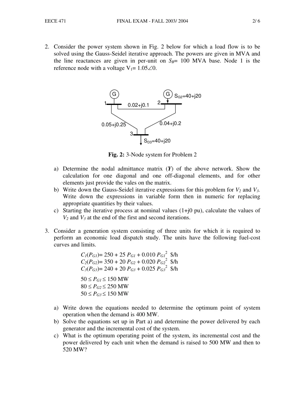
2. Consider the power system shown in Fig. 2 below for which a load flow is to be
solved using the Gauss-Seidel iterative approach. The powers are given in MVA and
the line reactances are given in per-unit on SB= 100 MVA base. Node 1 is the
reference node with a voltage V1= 1.05∠0.
G
3
2
1
G
SD3=40+j20
SG2=40+j20
0.04+j0.2
0.05+j0.25
0.02+j0.1
Fig. 2: 3-Node system for Problem 2
a) Determine the nodal admittance matrix (Y) of the above network. Show the
calculation for one diagonal and one off-diagonal elements, and for other
elements just provide the vales on the matrix.
b) Write down the Gauss-Seidel iterative expressions for this problem for V2 and V3.
Write down the expressions in variable form then in numeric for replacing
appropriate quantities by their values.
c) Starting the iterative process at nominal values (1+j0 pu), calculate the values of
V2 and V3 at the end of the first and second iterations.
3. Consider a generation system consisting of three units for which it is required to
perform an economic load dispatch study. The units have the following fuel-cost
curves and limits.
C1(PG1)= 250 + 25 PG1 + 0.010 PG1
2 $/h
C2(PG2)= 350 + 20 PG2 + 0.020 PG2
2 $/h
C3(PG3)= 240 + 20 PG3 + 0.025 PG3
2 $/h
50 ≤ PG1 ≤ 150 MW
80 ≤ PG2 ≤ 250 MW
50 ≤ PG3 ≤ 150 MW
a) Write down the equations needed to determine the optimum point of system
operation when the demand is 400 MW.
b) Solve the equations set up in Part a) and determine the power delivered by each
generator and the incremental cost of the system.
c) What is the optimum operating point of the system, its incremental cost and the
power delivered by each unit when the demand is raised to 500 MW and then to
520 MW?
EECE 471
FINAL EXAM - FALL 2003/ 2004
3/ 6
4. Consider the system shown in Fig. 3 below, which has the following data in per unit
on a 10 MVA base:
V1= 1 ∠0
ZL= j 0.2
SD1= 0.4 + j 0.2
SD2= 0.8 + j 0.4
The generator rating is 15 MVA at 0.9 PF.
jQ2
S1
SD1
SD2
IL
ZL
G
Fig. 3: System of two nodes for Problem 4
a) Use a Gauss-Seidel iterative method to determine V2 when Q2 is 0. Set up the
iterative equation of V2 and carry out 4 iterations only.
b) What are the line current IL and the complex power S1 supplied by the generator?
Is the complex power supplied within the capability limit of the generator?
Explain.
c) What would be the reactive power Q2 if |V2| is to be regulated to 1? Under these
conditions what is the line current IL and the complex power S1 supplied by the
generator?
d) If you were a system designer in a power company, would you recommend
installing a capacitor bank to supply Q2? Can Q2 be made smaller? If so how
small can Q2 be made approximately? Explain.
5. Write a 100 to 150 words abstract explaining what was your project about, the scope
of work that you have done, the methodology followed or main topics discussed, the
main results, conclusions, or recommendations that you achieved. Then explain with
just enough details to specifically clarify your personal contribution to the project.
EECE 471
FINAL EXAM - FALL 2003/ 2004
4/ 6
Fundamentals of Power Systems Analysis (EECE 471)
FORMULAE
•
Ch.4: Transmission Line Modeling
�
Complex Power Flow on Medium Line:
12
*
2
1
*
2
1
2
1
*
12
2
jθ
e
Z
V
V
Z
V
V
Y
S
−
+
=
For S21 exchange indices 1 and 2 in above equation
�
Power Flow on a short loss-less line:
12
2
1
21
12
sinθ
X
V V
P
P
=
= −
jX
R
l
z
Z
+
× =
=
12
2
1
2
1
12
cos
=
θ
X
V
V
X
V
Q
−
l
y
Y
×
=
12
2
1
2
2
21
cos
=
Q
θ
X
V
V
X
V
−
l: length of line
�
Power Circle Diagram
Both circles have a radius:
Z
V V
B
2
1
=
,
Z
Z
V
∠
2
1
C1 =
Z
Z
V
∠
2
2
2
-
=
C
�
Power transmission capability:
l
P
l
Z
V
P
SIL
c
β
θ
β
θ
sin
sin
sin
sin
=
12
12
2
1
12
=
( )
γ
β
= Im
C1
C2
S12
-S21
θ12
θ12
EECE 471
FINAL EXAM - FALL 2003/ 2004
5/ 6
•
∗Ch.5: Transformers and the Per-Unit System
B
B
B
ll
B
B
S
V
S
V
Z
2
3
2
=
=
Φ
B
pu
actual
Z
Z
Z
=
n
B
o
B
o
pu
n
B
actual
n
pu
Z
Z
Z
Z
Z
Z
=
=
•
*Ch.6: Generator Capability Limit
m
s
a a
G
X
E V
P
sinδ
=
⎟⎟
⎠
⎞
⎜⎜
⎝
⎛
−
=
a
m
a
s
a
G
V
E
X
V
Q
cosδ
s
a
a
X
E
V
max
=
ρ
f
a
k i
E
=
•
∗Ch.9: Nodal Admittance Matrix
I = Y V
� Yii is the sum of all admittances connected to node i;
� Yik is the negative of the series admittance between nodes i and k.
A transformer between nodes i and k can be modeled using a Π-equivalent as
shown below:
y
Ii
1 : n
Ii/n
Vi
n Vi
Vk
Ik
+
Vi
_
+
Vk
_
n y
y (n2-n)
y (1-n)
s
a
X
V
2
−
rated
φ
G
Q
G
P
ρ
max
2
tan δ
s
a
X
V
EECE 471
FINAL EXAM - FALL 2003/ 2004
6/ 6
•
Ch.10: Power Flow Analysis
*
*
1
*
k
ik
n
k
i
i i
i
Y V
V
V I
S
=
∑
=
=
i= 2, 3 …n
Di
Gi
i
S
S
S
−
=
∆
ik
ik
ik
jB
G
Y
+
=
k
i
ik
θ
θ
θ
−
=
(
ik )
ik
ik
ik
k
i
n
k
ic
B
VV G
P
θ
θ
sin
cos
1
+
= ∑
=
(
ik )
ik
ik
ik
k
i
n
k
ic
B
VV G
Q
θ
θ
cos
sin
1
−
= ∑
=
• Gauss-Seidel Load Flow:
⎥
⎥
⎥
⎦
⎤
⎢
⎢
⎢
⎣
⎡
− ∑
=
≠
=
k
ik
i
k
n
k
i
i
ii
i
Y V
V
S
Y
V
1
*
*
1
i= 2, 3 … n
•
Ch.11: Economic Operation of Power Systems
Minimize
(
Gi )
i
m
i
T
C P
C
=1
= ∑
Subject to
D
Gi
m
i
P
P
=
∑
=1
and
max
min
Gi
Gi
Gi
P
P
P
≤
≤
i=1 … m
(
)
2
Gi
Gi
Gi
i
P
P
C P
γ
β
α
+
+
=
iV
Gi
Gi
Gi
jQ
P
S
+
=
Di
Di
Di
jQ
P
S
+
=
Sic =
*
*
1
k
ik
n
i k
Y V
V
=
∑