
EECE 471 Midterm, Fall 2001
American University of Beirut · Fundamentals of Power Systems Analysis · 2 pages
More EECE 471 files
Show the text of this exam
ELEG 071E
MIDTERM - FALL 2001/ 2002
Page 1/ 2
S. KARAKI
AMERICAN UNIVERSITY OF BEIRUT
FALL 2001/2002
FACULTY OF ENGINEERING AND ARCHITECTURE
MIDTERM
POWER SYSTEMS FUNDAMENTALS (ELEG 071E)
OPEN BOOK (1.5 HOUR)
December 4, 2001
PROGRAMMABLE CALCULATORS ARE NOT ALLOWED
THIS QUESTION SHEET MUST BE RETURNED WITH THE ANSWER BOOKLET.
NAME: _________________________
ID#: _________________________
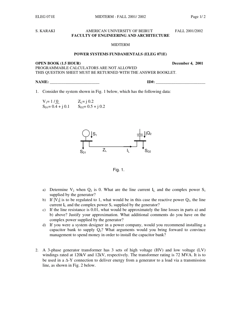
1. Consider the system shown in Fig. 1 below, which has the following data:
V1= 1 / 0
ZL= j 0.2
SD1= 0.4 + j 0.1
SD2= 0.5 + j 0.2
jQ2
S1
SD1
SD2
IL
ZL
Fig. 1.
a) Determine V2 when Q2 is 0. What are the line current IL and the complex power S1
supplied by the generator?
b) If |V2| is to be regulated to 1, what would be in this case the reactive power Q2, the line
current IL and the complex power S1 supplied by the generator?
c) If the line resistance is 0.01, what would be approximately the line losses in parts a) and
b) above? Justify your approximation. What additional comments do you have on the
complex power supplied by the generator?
d) If you were a system designer in a power company, would you recommend installing a
capacitor bank to supply Q2? What arguments would you bring forward to convince
management to spend money in order to install the capacitor bank?
2. A 3-phase generator transformer has 3 sets of high voltage (HV) and low voltage (LV)
windings rated at 120kV and 12kV, respectively. The transformer rating is 72 MVA. It is to
be used in a ∆-Y connection to deliver energy from a generator to a load via a transmission
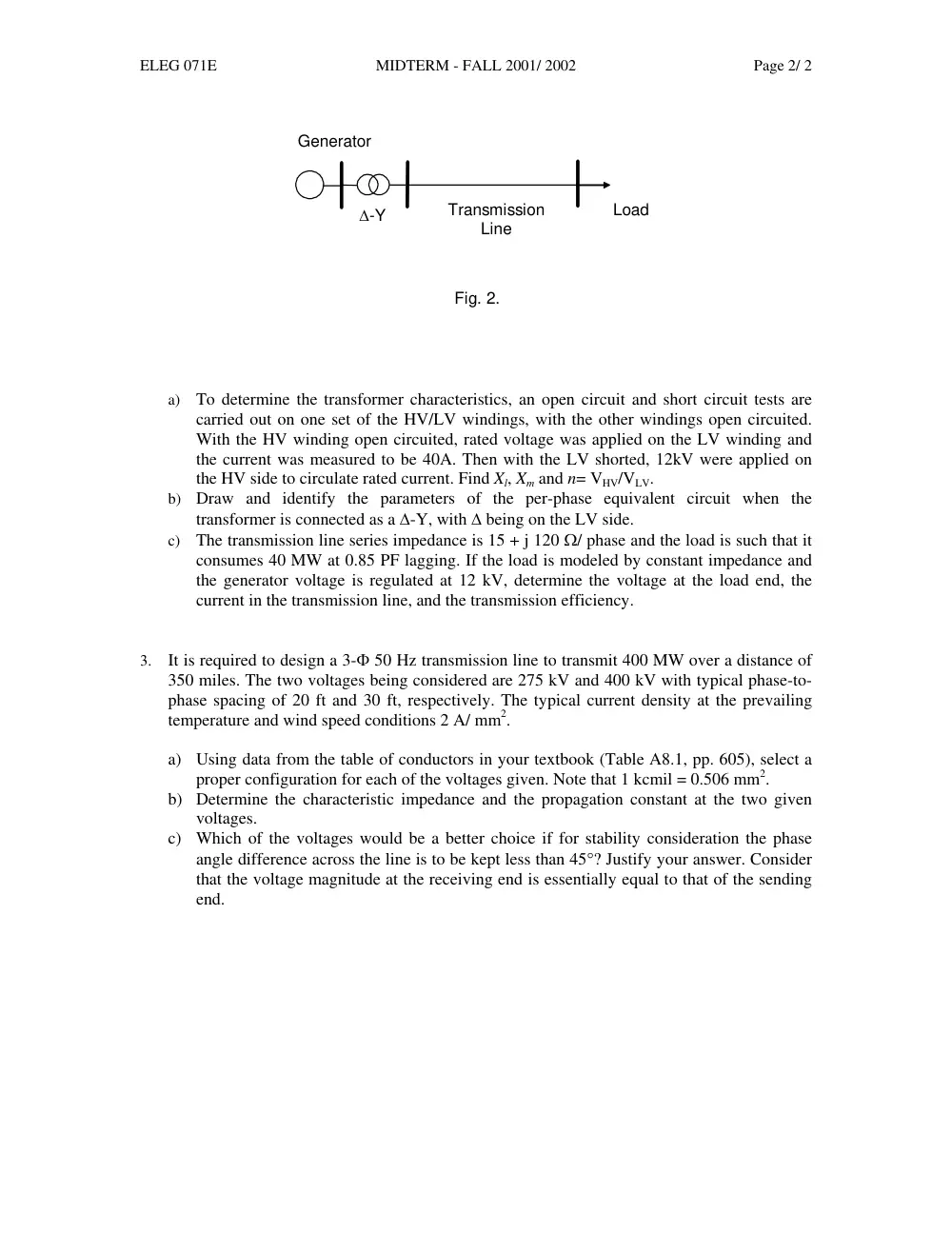
line, as shown in Fig. 2 below.
ELEG 071E
MIDTERM - FALL 2001/ 2002
Page 2/ 2
∆-Y
Load
Fig. 2.
Transmission
Line
Generator
a) To determine the transformer characteristics, an open circuit and short circuit tests are
carried out on one set of the HV/LV windings, with the other windings open circuited.
With the HV winding open circuited, rated voltage was applied on the LV winding and
the current was measured to be 40A. Then with the LV shorted, 12kV were applied on
the HV side to circulate rated current. Find Xl, Xm and n= VHV/VLV.
b) Draw and identify the parameters of the per-phase equivalent circuit when the
transformer is connected as a ∆-Y, with ∆ being on the LV side.
c) The transmission line series impedance is 15 + j 120 Ω/ phase and the load is such that it
consumes 40 MW at 0.85 PF lagging. If the load is modeled by constant impedance and
the generator voltage is regulated at 12 kV, determine the voltage at the load end, the
current in the transmission line, and the transmission efficiency.
3. It is required to design a 3-Φ 50 Hz transmission line to transmit 400 MW over a distance of
350 miles. The two voltages being considered are 275 kV and 400 kV with typical phase-to-
phase spacing of 20 ft and 30 ft, respectively. The typical current density at the prevailing
temperature and wind speed conditions 2 A/ mm2.
a) Using data from the table of conductors in your textbook (Table A8.1, pp. 605), select a
proper configuration for each of the voltages given. Note that 1 kcmil = 0.506 mm2.
b) Determine the characteristic impedance and the propagation constant at the two given
voltages.
c) Which of the voltages would be a better choice if for stability consideration the phase
angle difference across the line is to be kept less than 45°? Justify your answer. Consider
that the voltage magnitude at the receiving end is essentially equal to that of the sending
end.