
EECE 471 Midterm, Fall 2002
American University of Beirut · Fundamentals of Power Systems Analysis · 2 pages
More EECE 471 files
Show the text of this exam
S. KARAKI
AMERICAN UNIVERSITY OF BEIRUT
FALL 2002/2003
FACULTY OF ENGINEERING AND ARCHITECTURE
MIDTERM
FUNDAMENTALS OF ELECTRIC POWER SYSTEMS
(EECE 071E)
CLOSED BOOK (1.5 HOUR)
December 10, 2002
PROGRAMMABLE CALCULATORS ARE NOT ALLOWED
THIS QUESTION SHEET MUST BE RETURNED WITH THE ANSWER BOOKLET.
NAME: _________________________
ID#: _________________________
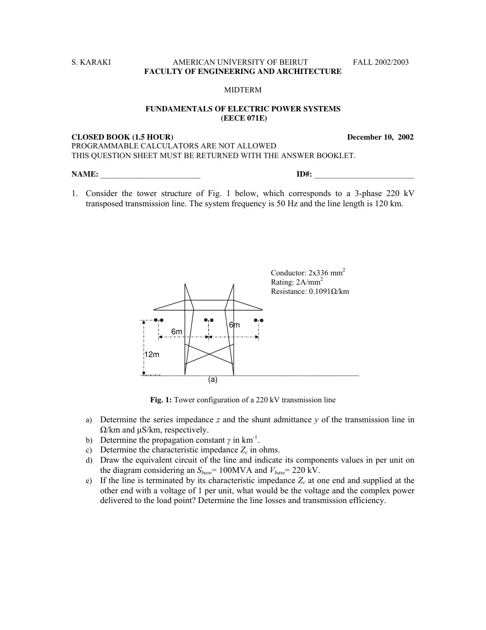
1. Consider the tower structure of Fig. 1 below, which corresponds to a 3-phase 220 kV
transposed transmission line. The system frequency is 50 Hz and the line length is 120 km.
Conductor: 2x336 mm2
Rating: 2A/mm2
Resistance: 0.1091Ω/km
6m
6m
12m
(a)
Fig. 1: Tower configuration of a 220 kV transmission line
a) Determine the series impedance z and the shunt admittance y of the transmission line in
Ω/km and µS/km, respectively.
b) Determine the propagation constant γ in km-1.
c) Determine the characteristic impedance Zc in ohms.
d) Draw the equivalent circuit of the line and indicate its components values in per unit on
the diagram considering an Sbase= 100MVA and Vbase= 220 kV.
e) If the line is terminated by its characteristic impedance Zc at one end and supplied at the
other end with a voltage of 1 per unit, what would be the voltage and the complex power
delivered to the load point? Determine the line losses and transmission efficiency.
EECE 071E
MIDTERM - FALL 2002/ 2003
Page 2/ 2
2
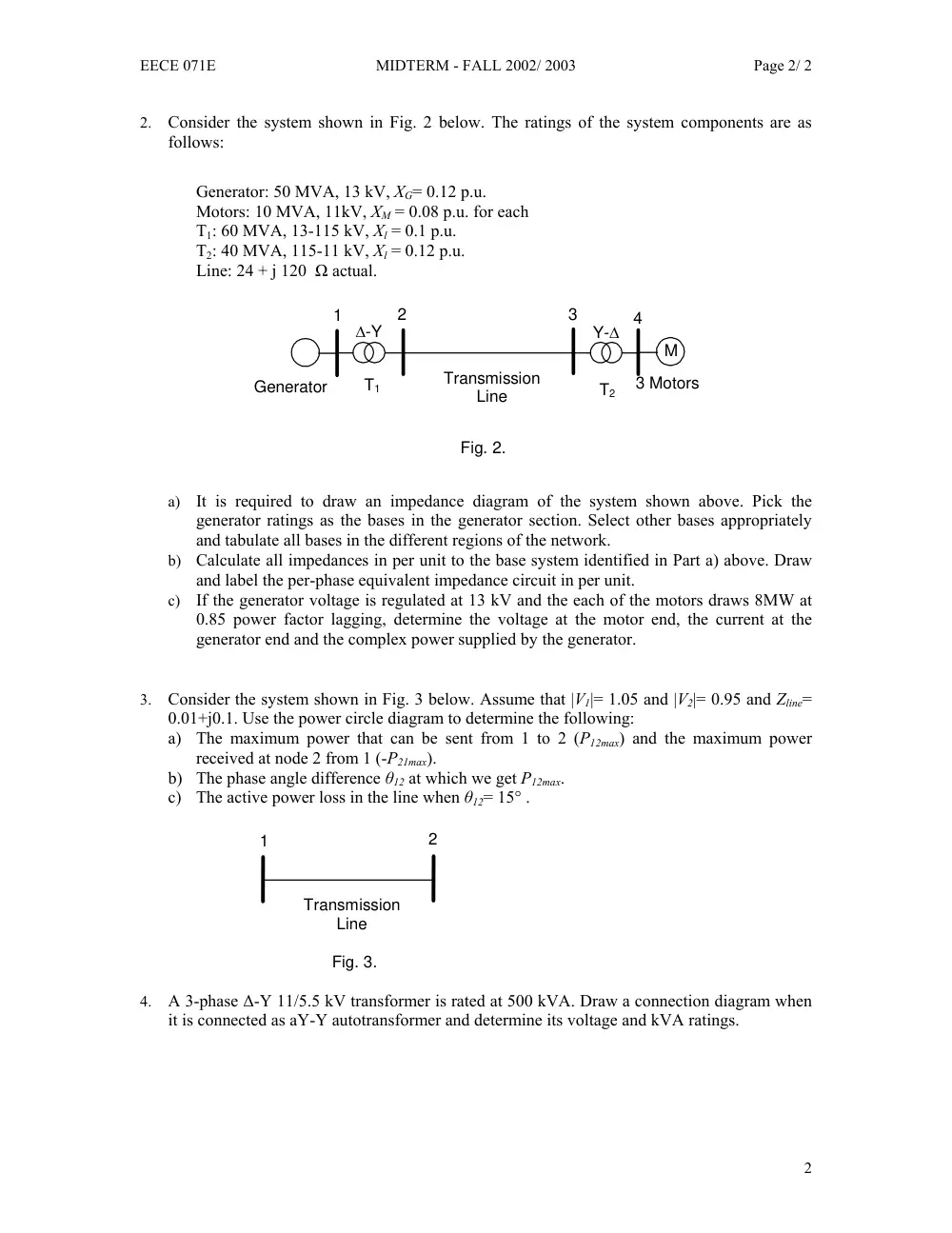
2. Consider the system shown in Fig. 2 below. The ratings of the system components are as
follows:
Generator: 50 MVA, 13 kV, XG= 0.12 p.u.
Motors: 10 MVA, 11kV, XM = 0.08 p.u. for each
T1: 60 MVA, 13-115 kV, Xl = 0.1 p.u.
T2: 40 MVA, 115-11 kV, Xl = 0.12 p.u.
Line: 24 + j 120 Ω actual.
∆-Y
Fig. 2.
Transmission
Line
M
Y-∆
1
T1
T2
2
3
4
3 Motors
Generator
a) It is required to draw an impedance diagram of the system shown above. Pick the
generator ratings as the bases in the generator section. Select other bases appropriately
and tabulate all bases in the different regions of the network.
b) Calculate all impedances in per unit to the base system identified in Part a) above. Draw
and label the per-phase equivalent impedance circuit in per unit.
c) If the generator voltage is regulated at 13 kV and the each of the motors draws 8MW at
0.85 power factor lagging, determine the voltage at the motor end, the current at the
generator end and the complex power supplied by the generator.
3. Consider the system shown in Fig. 3 below. Assume that |V1|= 1.05 and |V2|= 0.95 and Zline=
0.01+j0.1. Use the power circle diagram to determine the following:
a) The maximum power that can be sent from 1 to 2 (P12max) and the maximum power
received at node 2 from 1 (-P21max).
b) The phase angle difference θ12 at which we get P12max.
c) The active power loss in the line when θ12= 15° .
Fig. 3.
Transmission
Line
1
2
4. A 3-phase ∆-Y 11/5.5 kV transformer is rated at 500 kVA. Draw a connection diagram when
it is connected as aY-Y autotransformer and determine its voltage and kVA ratings.