
MECH 420 Problems Chap 6, Fall 2012
American University of Beirut · Mechanical Design · 31 pages
Showing the first 10 of 31 pages. Download the PDF to see all of it.
More MECH 420 files
- Problems Chap 4 · Fall 2012ProblemsView
- Problems Chap 7 · Fall 2012ProblemsView
- Problems Chap 8 · Fall 2012ProblemsView
- Problems Chap 9 · Fall 2012ProblemsView
- Problems Problem Chap 1 · Fall 2012ProblemsView
- Problems Problem Chap 2 · Fall 2012ProblemsView
- Problems Problem Chap 3 · Fall 2012ProblemsView
- Problems Problem Chap 5 · Fall 2012ProblemsView
Show the text of this problems
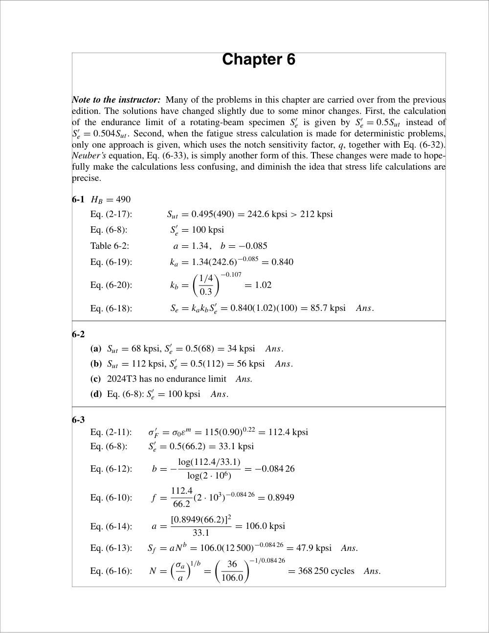
Chapter 6
Note to the instructor: Many of the problems in this chapter are carried over from the previous
edition. The solutions have changed slightly due to some minor changes. First, the calculation
of the endurance limit of a rotating-beam specimen S′
e is given by S′
e = 0.5Sut instead of
S′
e = 0.504Sut. Second, when the fatigue stress calculation is made for deterministic problems,
only one approach is given, which uses the notch sensitivity factor, q, together with Eq. (6-32).
Neuber’s equation, Eq. (6-33), is simply another form of this. These changes were made to hope-
fully make the calculations less confusing, and diminish the idea that stress life calculations are
precise.
6-1 HB = 490
Eq. (2-17):
Sut = 0.495(490) = 242.6 kpsi > 212 kpsi
Eq. (6-8):
S′
e = 100 kpsi
Table 6-2:
a = 1.34,
b = −0.085
Eq. (6-19):
ka = 1.34(242.6)−0.085 = 0.840
Eq. (6-20):
kb =
�1/4
0.3
�−0.107
= 1.02
Eq. (6-18):
Se = kakbS′
e = 0.840(1.02)(100) = 85.7 kpsi
Ans.
6-2
(a) Sut = 68 kpsi, S′
e = 0.5(68) = 34 kpsi
Ans.
(b) Sut = 112 kpsi, S′
e = 0.5(112) = 56 kpsi
Ans.
(c) 2024T3 has no endurance limit
Ans.
(d) Eq. (6-8): S′
e = 100 kpsi
Ans.
6-3
Eq. (2-11):
σ ′
F = σ0εm = 115(0.90)0.22 = 112.4 kpsi
Eq. (6-8):
S′
e = 0.5(66.2) = 33.1 kpsi
Eq. (6-12):
b = −log(112.4/33.1)
log(2 · 106)
= −0.084 26
Eq. (6-10):
f = 112.4
66.2 (2 · 103)−0.084 26 = 0.8949
Eq. (6-14):
a = [0.8949(66.2)]2
33.1
= 106.0 kpsi
Eq. (6-13):
Sf = aN b = 106.0(12 500)−0.084 26 = 47.9 kpsi
Ans.
Eq. (6-16):
N =
�σa
a
�1/b
=
� 36
106.0
�−1/0.084 26
= 368 250 cycles
Ans.
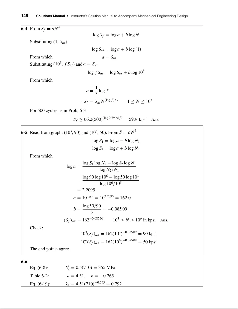
148
Solutions Manual • Instructor’s Solution Manual to Accompany Mechanical Engineering Design
6-4 From Sf = aN b
log Sf = log a + b log N
Substituting (1, Sut)
log Sut = log a + b log (1)
From which
a = Sut
Substituting (103, f Sut) and a = Sut
log f Sut = log Sut + b log 103
From which
b = 1
3 log f
∴ Sf = Sut N (log f )/3
1 ≤ N ≤ 103
For 500 cycles as in Prob. 6-3
Sf ≥ 66.2(500)(log 0.8949)/3 = 59.9 kpsi
Ans.
6-5 Read from graph: (103, 90) and (106, 50). From S = aN b
log S1 = log a + b log N1
log S2 = log a + b log N2
From which
log a = log S1 log N2 − log S2 log N1
log N2/N1
= log 90 log 106 − log 50 log 103
log 106/103
= 2.2095
a = 10log a = 102.2095 = 162.0
b = log 50/90
3
= −0.085 09
(Sf )ax = 162−0.085 09
103 ≤ N ≤ 106 in kpsi
Ans.
Check:
103(Sf )ax = 162(103)−0.085 09 = 90 kpsi
106(Sf )ax = 162(106)−0.085 09 = 50 kpsi
The end points agree.
6-6
Eq. (6-8):
S′
e = 0.5(710) = 355 MPa
Table 6-2:
a = 4.51,
b = −0.265
Eq. (6-19):
ka = 4.51(710)−0.265 = 0.792
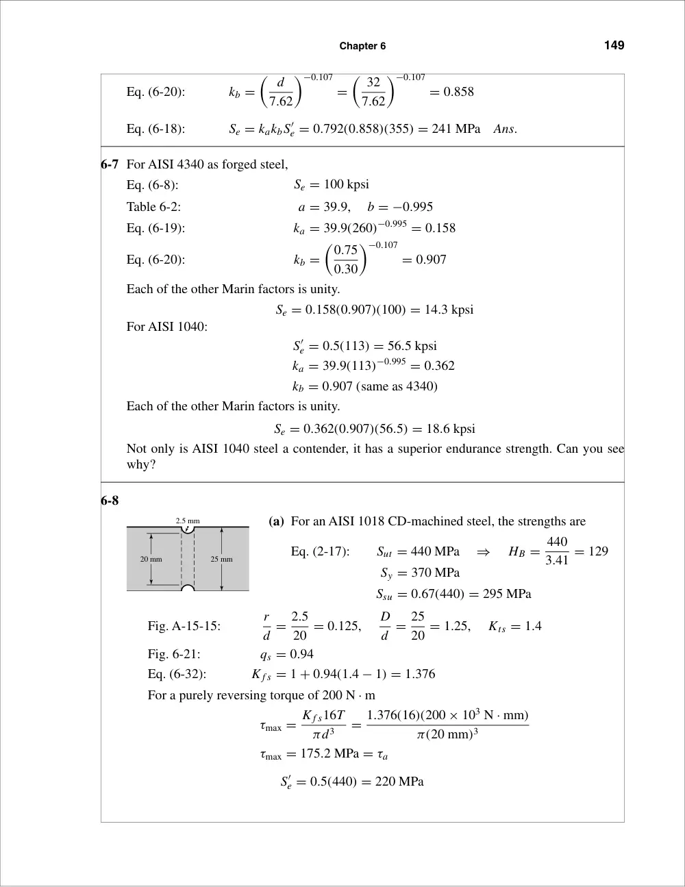
Chapter 6
149
Eq. (6-20):
kb =
� d
7.62
�−0.107
=
� 32
7.62
�−0.107
= 0.858
Eq. (6-18):
Se = kakbS′
e = 0.792(0.858)(355) = 241 MPa
Ans.
6-7 For AISI 4340 as forged steel,
Eq. (6-8):
Se = 100 kpsi
Table 6-2:
a = 39.9,
b = −0.995
Eq. (6-19):
ka = 39.9(260)−0.995 = 0.158
Eq. (6-20):
kb =
�0.75
0.30
�−0.107
= 0.907
Each of the other Marin factors is unity.
Se = 0.158(0.907)(100) = 14.3 kpsi
For AISI 1040:
S′
e = 0.5(113) = 56.5 kpsi
ka = 39.9(113)−0.995 = 0.362
kb = 0.907 (same as 4340)
Each of the other Marin factors is unity.
Se = 0.362(0.907)(56.5) = 18.6 kpsi
Not only is AISI 1040 steel a contender, it has a superior endurance strength. Can you see
why?
6-8
(a) For an AISI 1018 CD-machined steel, the strengths are
Eq. (2-17):
Sut = 440 MPa
⇒
HB = 440
3.41 = 129
Sy = 370 MPa
Ssu = 0.67(440) = 295 MPa
Fig. A-15-15:
r
d = 2.5
20 = 0.125,
D
d = 25
20 = 1.25,
Kts = 1.4
Fig. 6-21:
qs = 0.94
Eq. (6-32):
K f s = 1 + 0.94(1.4 − 1) = 1.376
For a purely reversing torque of 200 N · m
τmax = K f s16T
πd3
= 1.376(16)(200 × 103 N · mm)
π(20 mm)3
τmax = 175.2 MPa = τa
S′
e = 0.5(440) = 220 MPa
2.5 mm
20 mm
25 mm
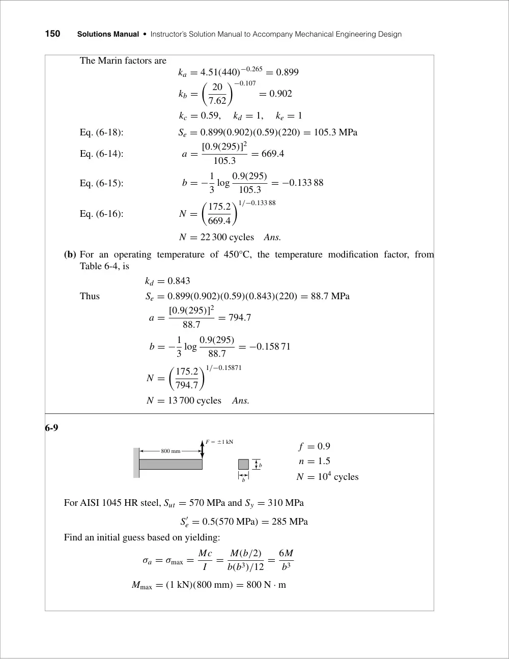
150
Solutions Manual • Instructor’s Solution Manual to Accompany Mechanical Engineering Design
The Marin factors are
ka = 4.51(440)−0.265 = 0.899
kb =
� 20
7.62
�−0.107
= 0.902
kc = 0.59,
kd = 1,
ke = 1
Eq. (6-18):
Se = 0.899(0.902)(0.59)(220) = 105.3 MPa
Eq. (6-14):
a = [0.9(295)]2
105.3
= 669.4
Eq. (6-15):
b = −1
3 log 0.9(295)
105.3
= −0.133 88
Eq. (6-16):
N =
�175.2
669.4
�1/−0.133 88
N = 22 300 cycles
Ans.
(b) For an operating temperature of 450°C, the temperature modification factor, from
Table 6-4, is
kd = 0.843
Thus
Se = 0.899(0.902)(0.59)(0.843)(220) = 88.7 MPa
a = [0.9(295)]2
88.7
= 794.7
b = −1
3 log 0.9(295)
88.7
= −0.158 71
N =
�175.2
794.7
�1/−0.15871
N = 13 700 cycles
Ans.
6-9
f = 0.9
n = 1.5
N = 104 cycles
For AISI 1045 HR steel, Sut = 570 MPa and Sy = 310 MPa
S′
e = 0.5(570 MPa) = 285 MPa
Find an initial guess based on yielding:
σa = σmax = Mc
I
= M(b/2)
b(b3)/12 = 6M
b3
Mmax = (1 kN)(800 mm) = 800 N · m
F � �1 kN
b
b
800 mm
Chapter 6
151
σmax = Sy
n
⇒
6(800 × 103 N · mm)
b3
= 310 N/mm2
1.5
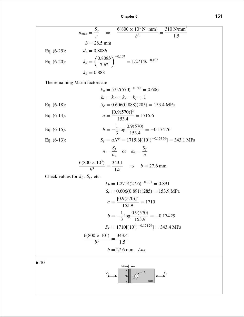
b = 28.5 mm
Eq. (6-25):
de = 0.808b
Eq. (6-20):
kb =
�0.808b
7.62
�−0.107
= 1.2714b−0.107
kb = 0.888
The remaining Marin factors are
ka = 57.7(570)−0.718 = 0.606
kc = kd = ke = kf = 1
Eq. (6-18):
Se = 0.606(0.888)(285) = 153.4 MPa
Eq. (6-14):
a = [0.9(570)]2
153.4
= 1715.6
Eq. (6-15):
b = −1
3 log 0.9(570)
153.4
= −0.174 76
Eq. (6-13):
Sf = aN b = 1715.6[(104)−0.174 76] = 343.1 MPa
n = Sf
σa
or
σa = Sf
n
6(800 × 103)
b3
= 343.1
1.5
⇒
b = 27.6 mm
Check values for kb, Se, etc.
kb = 1.2714(27.6)−0.107 = 0.891
Se = 0.606(0.891)(285) = 153.9 MPa
a = [0.9(570)]2
153.9
= 1710
b = −1
3 log 0.9(570)
153.9
= −0.174 29
Sf = 1710[(104)−0.174 29] = 343.4 MPa
6(800 × 103)
b3
= 343.4
1.5
b = 27.6 mm
Ans.
6-10
12
Fa
Fa
10
60
1018
152
Solutions Manual • Instructor’s Solution Manual to Accompany Mechanical Engineering Design
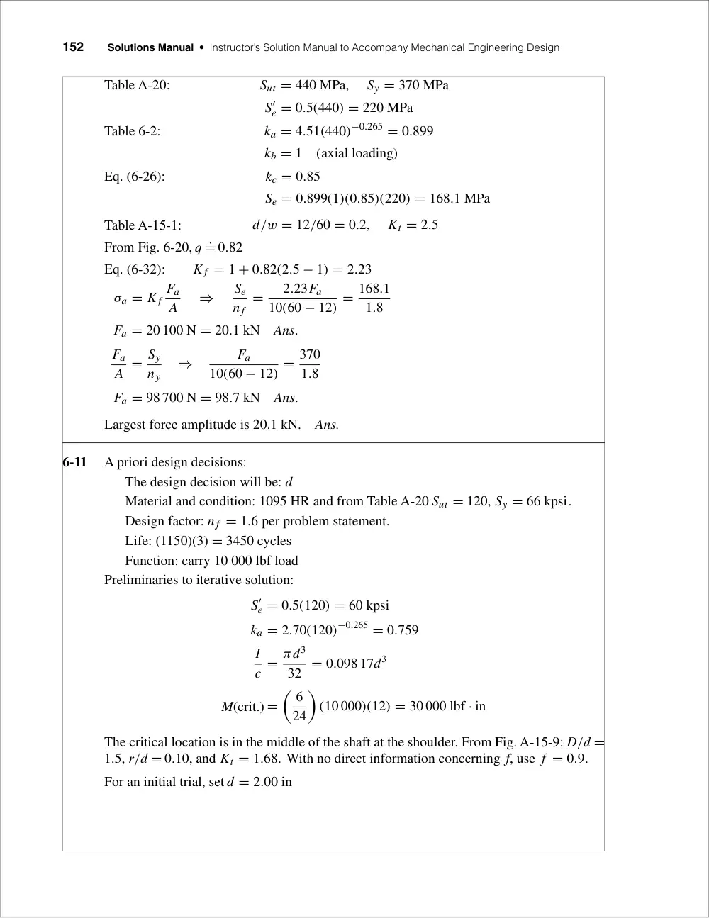
Table A-20:
Sut = 440 MPa,
Sy = 370 MPa
S′
e = 0.5(440) = 220 MPa
Table 6-2:
ka = 4.51(440)−0.265 = 0.899
kb = 1
(axial loading)
Eq. (6-26):
kc = 0.85
Se = 0.899(1)(0.85)(220) = 168.1 MPa
Table A-15-1:
d/w = 12/60 = 0.2,
Kt = 2.5
From Fig. 6-20, q ˙= 0.82
Eq. (6-32):
K f = 1 + 0.82(2.5 − 1) = 2.23
σa = K f
Fa
A
⇒
Se
n f
=
2.23Fa
10(60 − 12) = 168.1
1.8
Fa = 20 100 N = 20.1 kN
Ans.
Fa
A = Sy
ny
⇒
Fa
10(60 − 12) = 370
1.8
Fa = 98 700 N = 98.7 kN
Ans.
Largest force amplitude is 20.1 kN.
Ans.
6-11
A priori design decisions:
The design decision will be: d
Material and condition: 1095 HR and from Table A-20 Sut = 120, Sy = 66 kpsi.
Design factor: n f = 1.6 per problem statement.
Life: (1150)(3) = 3450 cycles
Function: carry 10 000 lbf load
Preliminaries to iterative solution:
S′
e = 0.5(120) = 60 kpsi
ka = 2.70(120)−0.265 = 0.759
I
c = πd3
32 = 0.098 17d3
M(crit.) =
� 6
24
�
(10 000)(12) = 30 000 lbf · in
The critical location is in the middle of the shaft at the shoulder. From Fig. A-15-9: D/d =
1.5, r/d = 0.10, and Kt = 1.68. With no direct information concerning f, use f = 0.9.
For an initial trial, set d = 2.00 in
Chapter 6
153
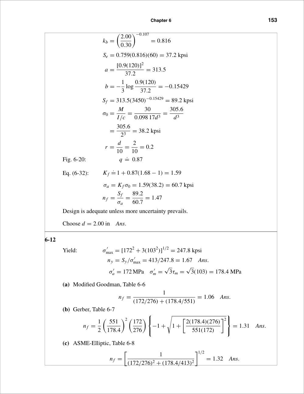
kb =
�2.00
0.30
�−0.107
= 0.816
Se = 0.759(0.816)(60) = 37.2 kpsi
a = [0.9(120)]2
37.2
= 313.5
b = −1
3 log 0.9(120)
37.2
= −0.15429
Sf = 313.5(3450)−0.15429 = 89.2 kpsi
σ0 = M
I/c =
30
0.098 17d3 = 305.6
d3
= 305.6
23
= 38.2 kpsi
r = d
10 = 2
10 = 0.2
Fig. 6-20:
q ˙= 0.87
Eq. (6-32):
K f ˙= 1 + 0.87(1.68 − 1) = 1.59
σa = K f σ0 = 1.59(38.2) = 60.7 kpsi
n f = Sf
σa
= 89.2
60.7 = 1.47
Design is adequate unless more uncertainty prevails.
Choose d = 2.00 in
Ans.
6-12
Yield:
σ ′
max = [1722 + 3(1032)]1/2 = 247.8 kpsi
ny = Sy/σ ′
max = 413/247.8 = 1.67
Ans.
σ ′
a = 172 MPa
σ ′
m =
√
3τm =
√
3(103) = 178.4 MPa
(a) Modified Goodman, Table 6-6
n f =
1
(172/276) + (178.4/551) = 1.06
Ans.
(b) Gerber, Table 6-7
n f = 1
2
� 551
178.4
�2 �172
276
�
−1 +
�
1 +
�2(178.4)(276)
551(172)
�2
= 1.31
Ans.
(c) ASME-Elliptic, Table 6-8
n f =
�
1
(172/276)2 + (178.4/413)2
�1/2
= 1.32
Ans.
154
Solutions Manual • Instructor’s Solution Manual to Accompany Mechanical Engineering Design
6-13
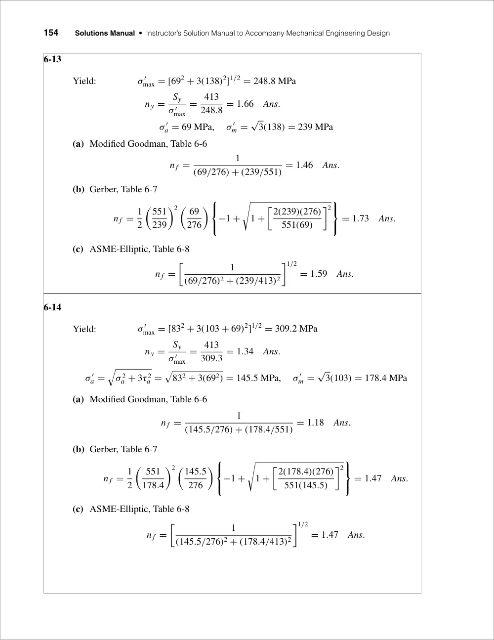
Yield:
σ ′
max = [692 + 3(138)2]1/2 = 248.8 MPa
ny =
Sy
σ ′max
= 413
248.8 = 1.66
Ans.
σ ′
a = 69 MPa,
σ ′
m =
√
3(138) = 239 MPa
(a) Modified Goodman, Table 6-6
n f =
1
(69/276) + (239/551) = 1.46
Ans.
(b) Gerber, Table 6-7
n f = 1
2
�551
239
�2 � 69
276
�
−1 +
�
1 +
�2(239)(276)
551(69)
�2
= 1.73
Ans.
(c) ASME-Elliptic, Table 6-8
n f =
�
1
(69/276)2 + (239/413)2
�1/2
= 1.59
Ans.
6-14
Yield:
σ ′
max = [832 + 3(103 + 69)2]1/2 = 309.2 MPa
ny =
Sy
σ ′max
= 413
309.3 = 1.34
Ans.
σ ′
a =
�
σ 2a + 3τ 2a =
�
832 + 3(692) = 145.5 MPa,
σ ′
m =
√
3(103) = 178.4 MPa
(a) Modified Goodman, Table 6-6
n f =
1
(145.5/276) + (178.4/551) = 1.18
Ans.
(b) Gerber, Table 6-7
n f = 1
2
� 551
178.4
�2 �145.5
276
�
−1 +
�
1 +
�2(178.4)(276)
551(145.5)
�2
= 1.47
Ans.
(c) ASME-Elliptic, Table 6-8
n f =
�
1
(145.5/276)2 + (178.4/413)2
�1/2
= 1.47
Ans.
Chapter 6
155
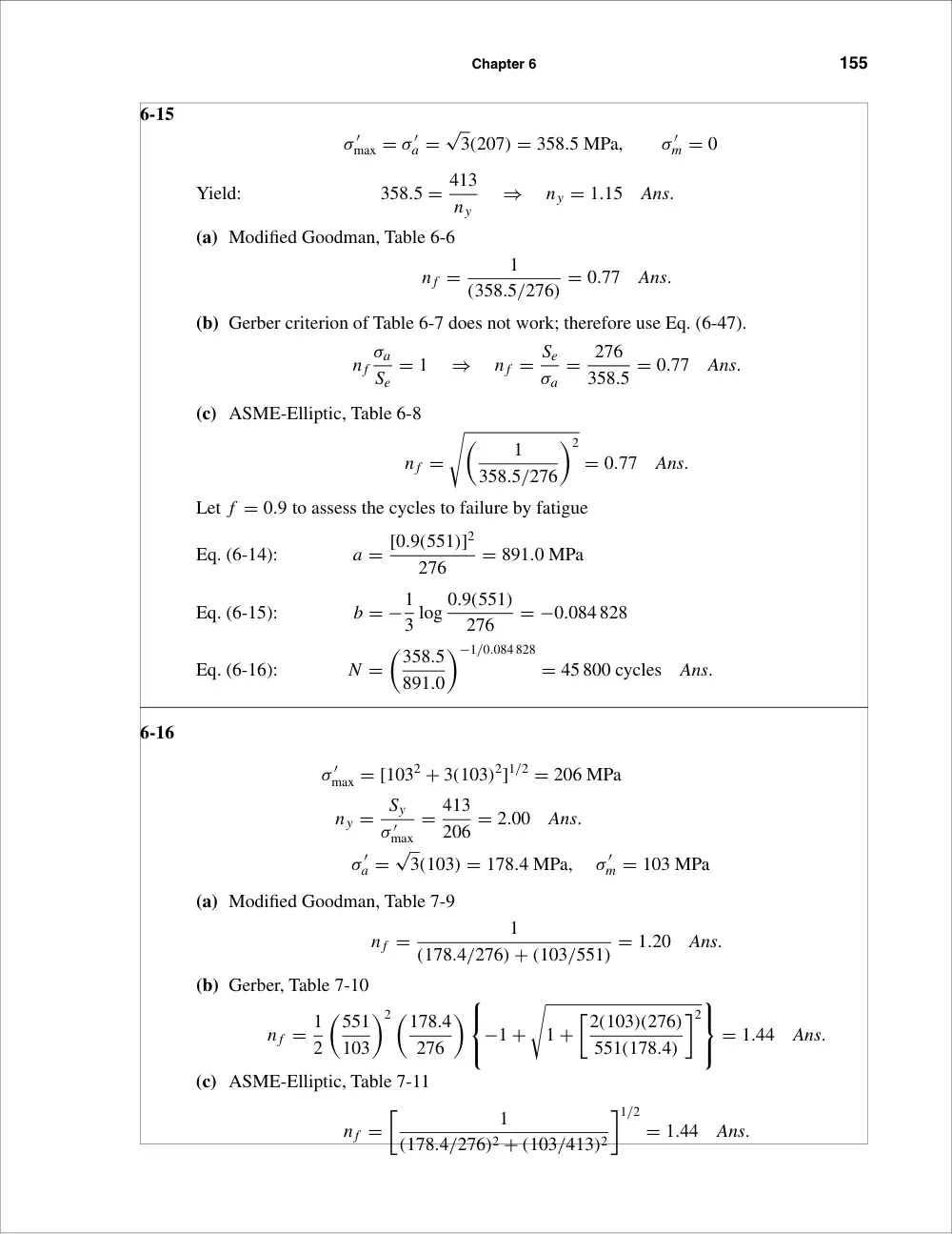
6-15
σ ′
max = σ ′
a =
√
3(207) = 358.5 MPa,
σ ′
m = 0
Yield:
358.5 = 413
ny
⇒
ny = 1.15
Ans.
(a) Modified Goodman, Table 6-6
n f =
1
(358.5/276) = 0.77
Ans.
(b) Gerber criterion of Table 6-7 does not work; therefore use Eq. (6-47).
n f
σa
Se
= 1
⇒
n f = Se
σa
= 276
358.5 = 0.77
Ans.
(c) ASME-Elliptic, Table 6-8
n f =
��
1
358.5/276
�2
= 0.77
Ans.
Let f = 0.9 to assess the cycles to failure by fatigue
Eq. (6-14):
a = [0.9(551)]2
276
= 891.0 MPa
Eq. (6-15):
b = −1
3 log 0.9(551)
276
= −0.084 828
Eq. (6-16):
N =
�358.5
891.0
�−1/0.084 828
= 45 800 cycles
Ans.
6-16
σ ′
max = [1032 + 3(103)2]1/2 = 206 MPa
ny =
Sy
σ ′max
= 413
206 = 2.00
Ans.
σ ′
a =
√
3(103) = 178.4 MPa,
σ ′
m = 103 MPa
(a) Modified Goodman, Table 7-9
n f =
1
(178.4/276) + (103/551) = 1.20
Ans.
(b) Gerber, Table 7-10
n f = 1
2
�551
103
�2 �178.4
276
�
−1 +
�
1 +
�2(103)(276)
551(178.4)
�2
= 1.44
Ans.
(c) ASME-Elliptic, Table 7-11
n f =
�
1
(178.4/276)2 + (103/413)2
�1/2
= 1.44
Ans.
156
Solutions Manual • Instructor’s Solution Manual to Accompany Mechanical Engineering Design
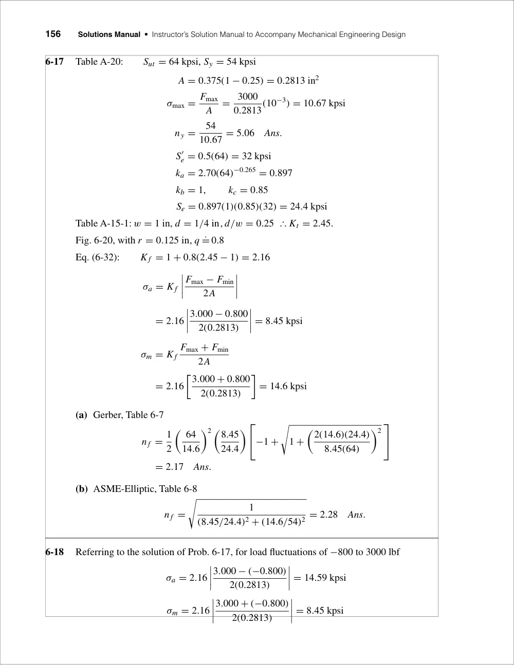
6-17
Table A-20:
Sut = 64 kpsi, Sy = 54 kpsi
A = 0.375(1 − 0.25) = 0.2813 in2
σmax = Fmax
A
= 3000
0.2813(10−3) = 10.67 kpsi
ny =
54
10.67 = 5.06
Ans.
S′
e = 0.5(64) = 32 kpsi
ka = 2.70(64)−0.265 = 0.897
kb = 1,
kc = 0.85
Se = 0.897(1)(0.85)(32) = 24.4 kpsi
Table A-15-1: w = 1 in, d = 1/4 in, d/w = 0.25 � Kt = 2.45.
Fig. 6-20, with r = 0.125 in, q ˙= 0.8
Eq. (6-32):
K f = 1 + 0.8(2.45 − 1) = 2.16
σa = K f
����
Fmax − Fmin
2A
����
= 2.16
����
3.000 − 0.800
2(0.2813)
���� = 8.45 kpsi
σm = K f
Fmax + Fmin
2A
= 2.16
�3.000 + 0.800
2(0.2813)
�
= 14.6 kpsi
(a) Gerber, Table 6-7
n f = 1
2
� 64
14.6
�2 �8.45
24.4
�
−1 +
�
1 +
�2(14.6)(24.4)
8.45(64)
�2
= 2.17
Ans.
(b) ASME-Elliptic, Table 6-8
n f =
�
1
(8.45/24.4)2 + (14.6/54)2 = 2.28
Ans.
6-18
Referring to the solution of Prob. 6-17, for load fluctuations of −800 to 3000 lbf
σa = 2.16
����
3.000 − (−0.800)
2(0.2813)
���� = 14.59 kpsi
σm = 2.16
����
3.000 + (−0.800)
2(0.2813)
���� = 8.45 kpsi
Chapter 6
157
(a) Table 6-7, DE-Gerber
n f = 1
2
� 64
8.45
�2 �14.59
24.4
�
−1 +
�
1 +
�2(8.45)(24.4)
64(14.59)
�2
= 1.60
Ans.
(b) Table 6-8, DE-Elliptic
n f =
�
1
(14.59/24.4)2 + (8.45/54)2 = 1.62
Ans.
6-19
Referring to the solution of Prob. 6-17, for load fluctuations of 800 to −3000 lbf
σa = 2.16
����
0.800 − (−3.000)
2(0.2813)
���� = 14.59 kpsi
σm = 2.16
�0.800 + (−3.000)
2(0.2813)
�
= −8.45 kpsi
(a) We have a compressive midrange stress for which the failure locus is horizontal at the
Se level.
n f = Se
σa
= 24.4
14.59 = 1.67
Ans.
(b) Same as (a)
n f = Se
σa
= 24.4
14.59 = 1.67
Ans.
6-20
Sut = 0.495(380) = 188.1 kpsi
S′
e = 0.5(188.1) = 94.05 kpsi
ka = 14.4(188.1)−0.718 = 0.335
For a non-rotating round bar in bending, Eq. (6-24) gives: de = 0.370d = 0.370(3/8) =
0.1388 in
kb =
�0.1388
0.3
�−0.107
= 1.086
Se = 0.335(1.086)(94.05) = 34.22 kpsi
Fa = 30 − 15
2
= 7.5 lbf,
Fm = 30 + 15
2
= 22.5 lbf
σm = 32Mm
πd3
= 32(22.5)(16)
π(0.3753) (10−3) = 69.54 kpsi
158
Solutions Manual • Instructor’s Solution Manual to Accompany Mechanical Engineering Design
σa = 32(7.5)(16)
π(0.3753) (10−3) = 23.18 kpsi
r = 23.18
69.54 = 0.333
0
(a) Modified Goodman, Table 6-6
n f =
1
(23.18/34.22) + (69.54/188.1) = 0.955
Since finite failure is predicted, proceed to calculate N
From Fig. 6-18, for Sut = 188.1 kpsi, f = 0.778
Eq. (6-14):
a = [0.7781(188.1)]2
34.22
= 625.8 kpsi
Eq. (6-15):
b = −1
3 log 0.778(188.1)
34.22
= −0.210 36
σa
Sf
+ σm
Sut
= 1
⇒
Sf =
σa
1 − (σm/Sut) =
23.18
1 − (69.54/188.1) = 36.78 kpsi
Eq. (7-15) with σa = Sf
N =
�36.78
625.8
�1/−0.210 36
= 710 000 cycles
Ans.
(b) Gerber, Table 6-7
n f = 1
2
�188.1
69.54
�2 �23.18
34.22
�
−1 +
�
1 +
�2(69.54)(34.22)
188.1(23.18)
�2
= 1.20
Thus, infinite life is predicted (N ≥ 106 cycles).
Ans.
6-21
(a)
I = 1
12(18)(33) = 40.5 mm4
y = Fl3
3E I
⇒
F = 3E I y
l3
Fmin = 3(207)(109)(40.5)(10−12)(2)(10−3)
(1003)(10−9)
= 50.3 N
Ans.
Fmax = 6
2(50.3) = 150.9 N
Ans.
(b)
M = 0.1015F N · m
A = 3(18) = 54 mm2
F
F
M
101.5 mm
Chapter 6
159
Curved beam:
rn =
h
ln(ro/ri) =
3
ln(6/3) = 4.3281 mm
rc = 4.5 mm,
e = rc − rn = 4.5 − 4.3281 = 0.1719 mm
σi = − Mci
Aeri
− F
A = −(0.1015F)(1.5 − 0.1719)
54(0.1719)(3)(10−3)
− F
54 = −4.859F MPa
σo = Mco
Aero
− F
A = (0.1015F)(1.5 + 0.1719)
54(0.1719)(6)(10−3)
− F
54 = 3.028F MPa
(σi)min = −4.859(150.9) = −733.2 MPa
(σi)max = −4.859(50.3) = −244.4 MPa
(σo)max = 3.028(150.9) = 456.9 MPa
(σo)min = 3.028(50.3) = 152.3 MPa
Eq. (2-17)
Sut = 3.41(490) = 1671 MPa
Per the problem statement, estimate the yield as Sy = 0.9Sut = 0.9(1671) =
1504 MPa. Then from Eq. (6-8), S′
e = 700 MPa; Eq. (6-19), ka = 1.58(1671)−0.085 =
0.841;
Eq.
(6-25) de = 0.808[18(3)]1/2 = 5.938 mm;
and Eq.
(6-20), kb =
(5.938/7.62)−0.107 = 1.027.
Se = 0.841(1.027)(700) = 605 MPa
At Inner Radius
(σi)a =
����
−733.2 + 244.4
2
���� = 244.4 MPa
(σi)m = −733.2 − 244.4
2
= −488.8 MPa
Load line:
σm = −244.4 − σa
Langer (yield) line:
σm = σa − 1504 = −244.4 − σa
Intersection:
σa = 629.8 MPa,
σm = −874.2 MPa
(Note that σa is more than 605 MPa)
Yield:
ny = 629.8
244.4 = 2.58
244.4
488.4
�m
�a
�1504
605
1504 MPa
160
Solutions Manual • Instructor’s Solution Manual to Accompany Mechanical Engineering Design
Fatigue:
n f = 605
244.4 = 2.48
Thus, the spring is likely to fail in fatigue at the
inner radius.
Ans.
At Outer Radius
(σo)a = 456.9 − 152.3
2
= 152.3 MPa
(σo)m = 456.9 + 152.3
2
= 304.6 MPa
Yield load line:
σm = 152.3 + σa
Langer line:
σm = 1504 − σa = 152.3 + σa
Intersection:
σa = 675.9 MPa,
σm = 828.2 MPa
ny = 675.9
152.3 = 4.44
Fatigue line:
σa = [1 − (σm/Sut)2]Se = σm − 152.3
605
�
1 −
� σm
1671
�2�
= σm − 152.3
σ 2
m + 4615.3σm − 3.4951(106) = 0
σm = −4615.3 +
�
4615.32 + 4(3.4951)(106)
2
= 662.2 MPa
σa = 662.2 − 152.3 = 509.9 MPa
n f = 509.9
152.3 = 3.35
Thus, the spring is not likely to fail in fatigue at the outer radius.
Ans.
6-22
The solution at the inner radius is the same as in Prob. 6-21. At the outer radius, the yield
solution is the same.
Fatigue line:
σa =
�
1 − σm
Sut
�
Se = σm − 152.3
605
�
1 − σm
1671
�
= σm − 152.3
1.362σm = 757.3
⇒
σm = 556.0 MPa
σa = 556.0 − 152.3 = 403.7 MPa
n f = 403.7
152.3 = 2.65
Ans.
Chapter 6
161
6-23
Preliminaries:
Table A-20:
Sut = 64 kpsi,
Sy = 54 kpsi
S′
e = 0.5(64) = 32 kpsi
ka = 2.70(64)−0.265 = 0.897
kb = 1
kc = 0.85
Se = 0.897(1)(0.85)(32) = 24.4 kpsi
Fillet:
Fig. A-15-5: D = 3.75 in, d = 2.5 in, D/d = 3.75/2.5 = 1.5, and r/d = 0.25/2.5 = 0.10
∴ Kt = 2.1. Fig. 6-20 with r � 0.25 in, q ˙= 0.82
Eq. (6-32):
K f = 1 + 0.82(2.1 − 1) = 1.90
σmax =
4
2.5(0.5) = 3.2 kpsi
σmin =
−16
2.5(0.5) = −12.8 kpsi
σa = 1.90
����
3.2 − (−12.8)
2
���� = 15.2 kpsi
σm = 1.90
�3.2 + (−12.8)
2
�
= −9.12 kpsi
ny =
����
Sy
σmin
���� =
����
54
−12.8
���� = 4.22
Since the midrange stress is negative,
Sa = Se = 24.4 kpsi
n f = Sa
σa
= 24.4
15.2 = 1.61
Hole:
Fig. A-15-1: d/w = 0.75/3.75 = 0.20, Kt = 2.5. Fig. 6-20, with r � 0.375 in, q ˙= 0.85
Eq. (6-32):
K f = 1 + 0.85(2.5 − 1) = 2.28
σmax =
4
0.5(3.75 − 0.75) = 2.67 kpsi
σmin =
−16
0.5(3.75 − 0.75) = −10.67 kpsi
σa = 2.28
����
2.67 − (−10.67)
2
���� = 15.2 kpsi
σm = 2.28 2.67 + (−10.67)
2
= −9.12 kpsi
162
Solutions Manual • Instructor’s Solution Manual to Accompany Mechanical Engineering Design
Since the midrange stress is negative,
ny =
����
Sy
σmin
���� =
����
54
−10.67
���� = 5.06
Sa = Se = 24.4 kpsi
n f = Sa
σa
= 24.4
15.2 = 1.61
Thus the design is controlled by the threat of fatigue equally at the fillet and the hole; the
minimum factor of safety is n f = 1.61.
Ans.
6-24
(a)
Curved beam in pure bending where M = −T
throughout. The maximum stress will occur at the
inner fiber where rc = 20 mm, but will be com-
pressive. The maximum tensile stress will occur at
the outer fiber where rc = 60 mm. Why?
Inner fiber where rc = 20 mm
rn =
h
ln(ro/ri) =
5
ln (22.5/17.5) = 19.8954 mm
e = 20 − 19.8954 = 0.1046 mm
ci = 19.8954 − 17.5 = 2.395 mm
A = 25 mm2
σi = Mci
Aeri
=
−T(2.395)10−3
25(10−6)0.1046(10−3)17.5(10−3)(10−6) = −52.34 T
(1)
where T is in N . m, and σi is in MPa.
σm = 1
2(−52.34T) = −26.17T,
σa = 26.17T
For the endurance limit, S′
e = 0.5(770) = 385 MPa
ka = 4.51(770)−0.265 = 0.775
de = 0.808[5(5)]1/2 = 4.04 mm
kb = (4.04/7.62)−0.107 = 1.07
Se = 0.775(1.07)385 = 319.3 MPa
For a compressive midrange component, σa = Se/n f . Thus,
26.17T = 319.3/3 ⇒ T = 4.07 N · m
T
T
Chapter 6
163
Outer fiber where rc = 60 mm
rn =
5
ln(62.5/57.5) = 59.96526 mm
e = 60 − 59.96526 = 0.03474 mm
co = 62.5 − 59.96526 = 2.535 mm
σo = − Mci
Aeri
= −
−T(2.535)10−3
25(10−6)0.03474(10−3)62.5(10−3)(10−6) = 46.7 T
Comparing this with Eq. (1), we see that it is less in magnitude, but the midrange compo-
nent is tension.
σa = σm = 1
2(46.7T) = 23.35T
Using Eq. (6-46), for modified Goodman, we have
23.35T
319.3 + 23.35T
770
= 1
3 ⇒ T = 3.22 N · m
Ans.
(b) Gerber, Eq. (6-47), at the outer fiber,
3(23.35T)
319.3
+
�3(23.35T)
770
�2
= 1
reduces to
T 2 + 26.51T − 120.83 = 0
T = 1
2
�
−26.51 +
�
26.512 + 4(120.83)
�
= 3.96 N · m
Ans.
(c) To guard against yield, use T of part (b) and the inner stress.
ny =
420
52.34(3.96) = 2.03
Ans.
6-25
From Prob. 6-24, Se = 319.3 MPa, Sy = 420 MPa, and Sut = 770 MPa
(a) Assuming the beam is straight,
σmax = 6M
bh2 =
6T
53[(10−3)3] = 48(106)T
Goodman:
24T
319.3 + 24T
770 = 1
3
⇒
T = 3.13 N · m
Ans.
(b) Gerber:
3(24)T
319.3 +
�3(24)T
770
�2
= 1
T 2 + 25.79T − 114.37 = 1
T = 1
2
�
−25.79 +
�
25.792 + 4(114.37)
�
= 3.86 N · m
Ans.
164
Solutions Manual • Instructor’s Solution Manual to Accompany Mechanical Engineering Design
(c) Using σmax = 52.34(106)T from Prob. 6-24,
ny =
420
52.34(3.86) = 2.08
Ans.
6-26
(a)
τmax = 16K f sTmax
πd3
Fig. 6-21 for HB > 200, r = 3 mm, qs .= 1
K f s = 1 + qs(Kts − 1)
K f s = 1 + 1(1.6 − 1) = 1.6
Tmax = 2000(0.05) = 100 N · m,
Tmin = 500
2000(100) = 25 N · m
τmax = 16(1.6)(100)(10−6)
π(0.02)3
= 101.9 MPa
τmin = 500
2000(101.9) = 25.46 MPa
τm = 1
2(101.9 + 25.46) = 63.68 MPa
τa = 1
2(101.9 − 25.46) = 38.22 MPa
Ssu = 0.67Sut = 0.67(320) = 214.4 MPa
Ssy = 0.577Sy = 0.577(180) = 103.9 MPa
S′
e = 0.5(320) = 160 MPa
ka = 57.7(320)−0.718 = 0.917
de = 0.370(20) = 7.4 mm
kb =
� 7.4
7.62
�−0.107
= 1.003
kc = 0.59
Se = 0.917(1.003)(0.59)(160) = 86.8 MPa
Modified Goodman, Table 6-6
n f =
1
(τa/Se) + (τm/Ssu) =
1
(38.22/86.8) + (63.68/214.4) = 1.36
Ans.
(b) Gerber, Table 6-7
n f = 1
2
�Ssu
τm
�2 τa
Se
−1 +
�
1 +
�2τmSe
Ssuτa
�2
= 1
2
�214.4
63.68
�2 38.22
86.8
−1 +
�
1 +
�2(63.68)(86.8)
214.4(38.22)
�2
= 1.70
Ans.
Chapter 6
165
6-27
Sy = 800 MPa, Sut = 1000 MPa
(a) From Fig. 6-20, for a notch radius of 3 mm and Sut = 1 GPa, q .= 0.92.
K f = 1 + q(Kt − 1) = 1 + 0.92(3 − 1) = 2.84
σmax = −K f
4P
πd2 = − 2.84(4)P
π(0.030)2 = −4018P
σm = −σa = 1
2(−4018P) = −2009P
T = f P
� D + d
4
�
Tmax = 0.3P
�0.150 + 0.03
4
�
= 0.0135P
From Fig. 6-21, qs .= 0.95. Also, Kts is given as 1.8. Thus,
K f s = 1 + qs(Kts − 1) = 1 + 0.95(1.8 − 1) = 1.76
τmax = 16K f sT
πd3
= 16(1.76)(0.0135P)
π(0.03)3
= 4482P
τa = τm = 1
2(4482P) = 2241P
Eqs. (6-55) and (6-56):
σ ′
a = σ ′
m =
�
(σa/0.85)2 + 3τ 2
a
�1/2 =
�
(−2009P/0.85)2 + 3(2241P)2�1/2 = 4545P
S′
e = 0.5(1000) = 500 MPa
ka = 4.51(1000)−0.265 = 0.723
kb =
� 30
7.62
�−0.107
= 0.864
Se = 0.723(0.864)(500) = 312.3 MPa
Modified Goodman:
σ ′
a
Se
+ σ ′
m
Sut
= 1
n
4545P
312.3(106) +
4545P
1000(106) = 1
3
⇒
P = 17.5(103) N = 16.1 kN
Ans.
Yield (conservative): ny =
Sy
σ ′a + σ ′m
ny =
800(106)
2(4545)(17.5)(103) = 5.03
Ans.
(actual):
σ ′
max =
�
σ 2
max + 3τ 2
max
�1/2 =
�
(−4018P)2 + 3(4482P)2�1/2
= 8741P
ny =
Sy
σ ′max
=
800(106)
8741(17.5)103 = 5.22
166
Solutions Manual • Instructor’s Solution Manual to Accompany Mechanical Engineering Design
(b) If the shaft is not rotating, τm = τa = 0.
σm = σa = −2009P
kb = 1
(axial)
kc = 0.85
(Since there is no tension, kc = 1 might be more appropriate.)
Se = 0.723(1)(0.85)(500) = 307.3 MPa
n f = 307.3(106)
2009P
⇒
P = 307.3(106)
3(2009)
= 51.0(103) N
= 51.0 kN
Ans.
Yield:
ny =
800(106)
2(2009)(51.0)(103) = 3.90
Ans.
6-28
From Prob. 6-27, K f = 2.84, K f s = 1.76, Se = 312.3 MPa
σmax = −K f
4Pmax
πd2 = −2.84
�(4)(80)(10−3)
π(0.030)2
�
= −321.4 MPa
σmin = 20
80(−321.4) = −80.4 MPa
Tmax = f Pmax
� D + d
4
�
= 0.3(80)(103)
�0.150 + 0.03
4
�
= 1080 N · m
Tmin = 20
80(1080) = 270 N · m
τmax = K f s
16Tmax
πd3
= 1.76
� 16(1080)
π(0.030)3(10−6)
�
= 358.5 MPa
τmin = 20
80(358.5) = 89.6 MPa
σa = 321.4 − 80.4
2
= 120.5 MPa
σm = −321.4 − 80.4
2
= −200.9 MPa
τa = 358.5 − 89.6
2
= 134.5 MPa
τm = 358.5 + 89.6
2
= 224.1 MPa
307.3
�m
�a
�800
800
Chapter 6
167
Eqs. (6-55) and (6-56):
σ ′
a =
�
(σa/0.85)2 + 3τ 2
a
�1/2 =
�
(120.5/0.85)2 + 3(134.5)2�1/2 = 272.7 MPa
σ ′
m =
�
(−200.9/0.85)2 + 3(224.1)2�1/2 = 454.5 MPa
Goodman:
(σa)e =
σ ′
a
1 − σ ′m/Sut
=
272.7
1 − 454.5/1000 = 499.9 MPa
Let f = 0.9
a = [0.9(1000)]2
312.3
= 2594 MPa
b = −1
3 log
�0.9(1000)
312.3
�
= −0.1532
N =
�(σa)e
a
�1/b
=
�499.9
2594
�1/−0.1532
= 46 520 cycles
Ans.
6-29
Sy = 490 MPa,
Sut = 590 MPa,
Se = 200 MPa
σm = 420 + 140
2
= 280 MPa,
σa = 420 − 140
2
= 140 MPa
Goodman:
(σa)e =
σa
1 − σm/Sut
=
140
1 − (280/590) = 266.5 MPa > Se ∴ finite life
a = [0.9(590)]2
200
= 1409.8 MPa
b = −1
3 log 0.9(590)
200
= −0.141 355
N =
� 266.5
1409.8
�−1/0.143 55
= 131 200 cycles
Nremaining = 131 200 − 50 000 = 81 200 cycles
Second loading:
(σm)2 = 350 + (−200)
2
= 75 MPa
(σa)2 = 350 − (−200)
2
= 275 MPa
(σa)e2 =
275
1 − (75/590) = 315.0 MPa
168
Solutions Manual • Instructor’s Solution Manual to Accompany Mechanical Engineering Design
(a) Miner’s method
N2 =
� 315
1409.8
�−1/0.141 355
= 40 200 cycles
n1
N1
+ n2
N2
= 1
⇒
50 000
131 200 +
n2
40 200 = 1
n2 = 24 880 cycles
Ans.
(b) Manson’s method
Two data points:
0.9(590 MPa),
103 cycles
266.5 MPa,
81 200 cycles
0.9(590)
266.5
=
a2(103)b2
a2(81 200)b2
1.9925 = (0.012 315)b2
b2 =
log 1.9925
log 0.012 315 = −0.156 789
a2 =
266.5
(81 200)−0.156 789 = 1568.4 MPa
n2 =
� 315
1568.4
�1/−0.156 789
= 27 950 cycles
Ans.
6-30
(a) Miner’s method
a = [0.9(76)]2
30
= 155.95 kpsi
b = −1
3 log 0.9(76)
30
= −0.119 31
σ1 = 48 kpsi,
N1 =
�
48
155.95
�1/−0.119 31
= 19 460 cycles
σ2 = 38 kpsi,
N2 =
�
38
155.95
�1/−0.119 31
= 137 880 cycles
σ3 = 32 kpsi,
N3 =
�
32
155.95
�1/−0.119 31
= 582 150 cycles
n1
N1
+ n2
N2
+ n3
N3
= 1
4000
19 460 + 60 000
137 880 +
n3
582 150 = 1
⇒
n3 = 209 160 cycles
Ans.
(b) Manson’s method
The life remaining after the first cycle is NR1 = 19 460 − 4000 = 15 460 cycles. The
two data points required to define S′
e,1 are [0.9(76), 103] and (48, 15 460).
0.9(76)
48
= a2(103)b2
a2(15 460)
⇒
1.425 = (0.064 683)b2
Chapter 6
169
b2 =
log(1.425)
log(0.064 683) = −0.129 342
a2 =
48
(15 460)−0.129 342 = 167.14 kpsi
N2 =
�
38
167.14
�−1/0.129 342
= 94 110 cycles
NR2 = 94 110 − 60 000 = 34 110 cycles
0.9(76)
38
=
a3(103)b3
a3(34 110)b3
⇒
1.8 = (0.029 317)b3
b3 =
log 1.8
log(0.029 317) = −0.166 531,
a3 =
38
(34 110)−0.166 531 = 216.10 kpsi
N3 =
� 32
216.1
�−1/0.166 531
= 95 740 cycles
Ans.
6-31
Using Miner’s method
a = [0.9(100)]2
50
= 162 kpsi
b = −1
3 log 0.9(100)
50
= −0.085 091
σ1 = 70 kpsi,
N1 =
� 70
162
�1/−0.085 091
= 19 170 cycles
σ2 = 55 kpsi,
N2 =
� 55
162
�1/−0.085 091
= 326 250 cycles
σ3 = 40 kpsi,
N3 → ∞
0.2N
19 170 +
0.5N
326 250 + 0.3N
∞
= 1
N = 83 570 cycles
Ans.
6-32
Given Sut = 245LN(1, 0.0508) kpsi
From Table 7-13:
a = 1.34, b = −0.086, C = 0.12
ka = 1.34 ¯S−0.086
ut
LN(1, 0.120)
= 1.34(245)−0.086LN(1, 0.12)
= 0.835LN(1, 0.12)
kb = 1.02
(as in Prob. 6-1)
Eq. (6-70)
Se = 0.835(1.02)LN(1, 0.12)[107LN(1, 0.139)]
¯Se = 0.835(1.02)(107) = 91.1 kpsi
170
Solutions Manual • Instructor’s Solution Manual to Accompany Mechanical Engineering Design
Now
CSe .= (0.122 + 0.1392)1/2 = 0.184
Se = 91.1LN(1, 0.184) kpsi
Ans.
6-33
A Priori Decisions:
• Material and condition: 1018 CD, Sut = 440LN(1, 0.03), and
Sy = 370LN(1, 0.061) MPa
• Reliability goal: R = 0.999
(z = −3.09)
• Function:
Critical location—hole
• Variabilities:
Cka = 0.058
Ckc = 0.125
Cφ = 0.138
CSe =
�
C2
ka + C2
kc + C2
φ
�1/2 = (0.0582 + 0.1252 + 0.1382)1/2 = 0.195
Ckc = 0.10
CFa = 0.20
Cσa = (0.102 + 0.202)1/2 = 0.234
Cn =
�
C2
Se + C2σa
1 + C2σa
=
�
0.1952 + 0.2342
1 + 0.2342
= 0.297
Resulting in a design factor n f of,
Eq. (6-88):
n f = exp[−(−3.09)
�
ln(1 + 0.2972) + ln
�
1 + 0.2972] = 2.56
• Decision: Set n f = 2.56
Now proceed deterministically using the mean values:
Table 6-10:
¯ka = 4.45(440)−0.265 = 0.887
kb = 1
Table 6-11:
¯kc = 1.43(440)−0.0778 = 0.891
Eq. (6-70):
¯S′
e = 0.506(440) = 222.6 MPa
Eq. (6-71):
¯Se = 0.887(1)0.891(222.6) = 175.9 MPa
From Prob. 6-10, K f = 2.23. Thus,
¯σa = ¯K f
¯Fa
A = ¯K f
¯Fa
t(60 − 12) =
¯Se
¯n f
and, t = ¯n f ¯K f ¯Fa
48 ¯Se
= 2.56(2.23)15(103)
48(175.9)
= 10.14 mm
Chapter 6
171
Decision: Depending on availability, (1) select t = 10 mm, recalculate n f and R, and
determine whether the reduced reliability is acceptable, or, (2) select t = 11 mm or
larger, and determine whether the increase in cost and weight is acceptable.
Ans.
6-34
Rotation is presumed. M and Sut are given as deterministic, but notice that σ is not; there-
fore, a reliability estimation can be made.
From Eq. (6-70):
S′
e = 0.506(110)LN(1, 0.138)
= 55.7LN(1, 0.138) kpsi
Table 6-10:
ka = 2.67(110)−0.265LN(1, 0.058)
= 0.768LN(1, 0.058)
Based on d = 1 in, Eq. (6-20) gives
kb =
� 1
0.30
�−0.107
= 0.879
Conservatism is not necessary
Se = 0.768[LN(1, 0.058)](0.879)(55.7)[LN(1, 0.138)]
¯Se = 37.6 kpsi
CSe = (0.0582 + 0.1382)1/2 = 0.150
Se = 37.6LN(1, 0.150)
Fig. A-15-14: D/d = 1.25, r/d = 0.125. Thus Kt = 1.70 and Eqs. (6-78), (6-79) and
Table 6-15 give
Kf =
1.70LN(1, 0.15)
1 +
�
2/
√
0.125
�
[(1.70 − 1)/(1.70)](3/110)
= 1.598LN(1, 0.15)
σ = Kf
32M
πd3 = 1.598[LN(1 − 0.15)]
�32(1400)
π(1)3
�
= 22.8LN(1, 0.15) kpsi
From Eq. (5-43), p. 242:
z = −
ln
�
(37.6/22.8)
�
(1 + 0.152)/(1 + 0.152)
�
�
ln[(1 + 0.152)(1 + 0.152)]
= −2.37
1.25"
M
M
1.00"
172
Solutions Manual • Instructor’s Solution Manual to Accompany Mechanical Engineering Design
From Table A-10, pf = 0.008 89
∴ R = 1 − 0.008 89 = 0.991
Ans.
Note: The correlation method uses only the mean of Sut; its variability is already included
in the 0.138. When a deterministic load, in this case M, is used in a reliability estimate, en-
gineers state, “For a Design Load of M, the reliability is 0.991.” They are in fact referring
to a Deterministic Design Load.
6-35
For completely reversed torsion, ka and kb of Prob. 6-34 apply, but kc must also be con-
sidered.
Eq. 6-74:
kc = 0.328(110)0.125LN(1, 0.125)
= 0.590LN(1, 0.125)
Note 0.590 is close to 0.577.
SSe = ka kb kc S′
e
= 0.768[LN(1, 0.058)](0.878)[0.590LN(1, 0.125)][55.7LN(1, 0.138)]
¯SSe = 0.768(0.878)(0.590)(55.7) = 22.2 kpsi
CSe = (0.0582 + 0.1252 + 0.1382)1/2 = 0.195
SSe = 22.2LN(1, 0.195) kpsi
Fig. A-15-15: D/d = 1.25, r/d = 0.125, then Kts = 1.40. From Eqs. (6-78), (6-79) and
Table 6-15
Kts =
1.40LN(1, 0.15)
1 +
�
2/
√
0.125
�
[(1.4 − 1)/1.4](3/110)
= 1.34LN(1, 0.15)
τ = Kts
16T
πd3
τ = 1.34[LN(1, 0.15)]
�16(1.4)
π(1)3
�
= 9.55LN(1, 0.15) kpsi
From Eq. (5-43), p. 242:
z = −
ln
�
(22.2/9.55)
�
(1 + 0.152)/(1 + 0.1952)
�
�
ln [(1 + 0.1952)(1 + 0.152)]
= −3.43
From Table A-10, pf = 0.0003
R = 1 − pf = 1 − 0.0003 = 0.9997
Ans.
For a design with completely-reversed torsion of 1400 lbf ·in, the reliability is 0.9997. The
improvement comes from a smaller stress-concentration factor in torsion. See the note at
the end of the solution of Prob. 6-34 for the reason for the phraseology.
Chapter 6
173
6-36
Sut = 58 kpsi
S′
e = 0.506(58)LN(1, 0.138)
= 29.3LN(1, 0.138) kpsi
Table 6-10:
ka = 14.5(58)−0.719LN(1, 0.11)
= 0.782LN(1, 0.11)
Eq. (6-24):
de = 0.37(1.25) = 0.463 in
kb =
�0.463
0.30
�−0.107
= 0.955
Se = 0.782[LN(1, 0.11)](0.955)[29.3LN(1, 0.138)]
¯Se = 0.782(0.955)(29.3) = 21.9 kpsi
CSe = (0.112 + 0.1382)1/2 = 0.150
Table A-16: d/D = 0, a/D = 0.1, A = 0.83 ∴ Kt = 2.27.
From Eqs. (6-78) and (6-79) and Table 6-15
Kf =
2.27LN(1, 0.10)
1 +
�
2/
√
0.125
�
[(2.27 − 1)/2.27](5/58)
= 1.783LN(1, 0.10)
Table A-16:
Z = π AD3
32
= π(0.83)(1.253)
32
= 0.159 in3
σ = Kf
M
Z = 1.783LN(1, 0.10)
� 1.6
0.159
�
= 17.95LN(1, 0.10) kpsi
¯σ = 17.95 kpsi
Cσ = 0.10
Eq. (5-43), p. 242:
z = −
ln
�
(21.9/17.95)
�
(1 + 0.102)/(1 + 0.152)
�
�
ln[(1 + 0.152)(1 + 0.102)]
= −1.07
Table A-10:
pf = 0.1423
R = 1 − pf = 1 − 0.1423 = 0.858
Ans.
For a completely-reversed design load Ma of 1400 lbf · in, the reliability estimate is 0.858.
M
M
1 D
4
1 "
D
Non-rotating
1
8
"
174
Solutions Manual • Instructor’s Solution Manual to Accompany Mechanical Engineering Design
6-37
For a non-rotating bar subjected to completely reversed torsion of Ta = 2400 lbf · in
From Prob. 6-36:
S′
e = 29.3LN(1, 0.138) kpsi
ka = 0.782LN(1, 0.11)
kb = 0.955
For kc use Eq. (6-74):
kc = 0.328(58)0.125LN(1, 0.125)
= 0.545LN(1, 0.125)
SSe = 0.782[LN(1, 0.11)](0.955)[0.545LN(1, 0.125)][29.3LN(1, 0.138)]
¯SSe = 0.782(0.955)(0.545)(29.3) = 11.9 kpsi
CSe = (0.112 + 0.1252 + 0.1382)1/2 = 0.216
Table A-16: d/D = 0, a/D = 0.1, A = 0.92, Kts = 1.68
From Eqs. (6-78), (6-79), Table 6-15
Kf s =
1.68LN(1, 0.10)
1 +
�
2/
√
0.125
�
[(1.68 − 1)/1.68](5/58)
= 1.403LN(1, 0.10)
Table A-16:
Jnet = π AD4
32
= π(0.92)(1.254)
32
= 0.2201
τa = Kf s
Tac
Jnet
= 1.403[LN(1, 0.10)]
�2.4(1.25/2)
0.2201
�
= 9.56LN(1, 0.10) kpsi
From Eq. (5-43), p. 242:
z = −
ln
�
(11.9/9.56)
�
(1 + 0.102)/(1 + 0.2162)
�
�
ln[(1 + 0.102)(1 + 0.2162)]
= −0.85
Table A-10, pf = 0.1977
R = 1 − pf = 1 − 0.1977 = 0.80
Ans.
6-38
This is a very important task for the student to attempt before starting Part 3. It illustrates
the drawback of the deterministic factor of safety method. It also identifies the a priori de-
cisions and their consequences.
The range of force fluctuation in Prob. 6-23 is −16 to +4 ki