
MECH 420 Problems Problem Chap 3, Fall 2012
American University of Beirut · Mechanical Design · 56 pages

Showing the first 10 of 56 pages. Download the PDF to see all of it.
More MECH 420 files
- Problems Chap 4 · Fall 2012ProblemsView
- Problems Chap 6 · Fall 2012ProblemsView
- Problems Chap 7 · Fall 2012ProblemsView
- Problems Chap 8 · Fall 2012ProblemsView
- Problems Chap 9 · Fall 2012ProblemsView
- Problems Problem Chap 1 · Fall 2012ProblemsView
- Problems Problem Chap 2 · Fall 2012ProblemsView
- Problems Problem Chap 5 · Fall 2012ProblemsView
Show the text of this problems
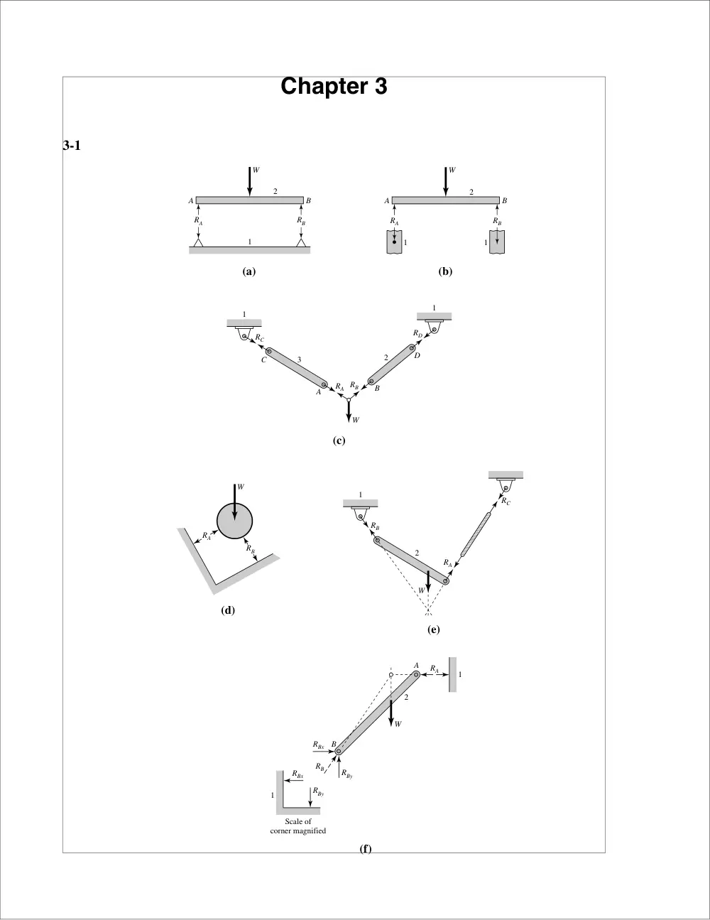
Chapter 3
3-1
1
RC
RA RB
RD
C
A
B
W
D
1
2
3
RB
RA
W
RB
RC
RA
2
1
W
RA
RBx
RBx
RBy
RBy
RB
2
1
1
Scale of
corner magnified
W
A
B
(e)
(f)
(d)
W
A
RA
RB
B
1
2
W
A
RA
RB
B
1
1
2
(a)
(b)
(c)
Chapter 3
15
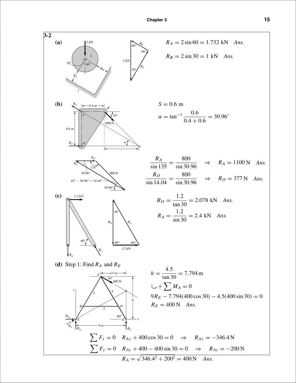
3-2
(a)
RA = 2 sin 60 = 1.732 kN
Ans.
RB = 2 sin 30 = 1 kN
Ans.
(b)
S = 0.6 m
α = tan−1
0.6
0.4 + 0.6 = 30.96◦
RA
sin 135 =
800
sin 30.96
⇒
RA = 1100 N
Ans.
RO
sin 14.04 =
800
sin 30.96
⇒
RO = 377 N
Ans.
(c)
RO =
1.2
tan 30 = 2.078 kN
Ans.
RA =
1.2
sin 30 = 2.4 kN
Ans.
(d) Step 1: Find RA and RE
h =
4.5
tan 30 = 7.794 m
�+
�
MA = 0
9RE − 7.794(400 cos 30) − 4.5(400 sin 30) = 0
RE = 400 N
Ans.
�
Fx = 0
RAx + 400 cos 30 = 0
⇒
RAx = −346.4 N
�
Fy = 0
RAy + 400 − 400 sin 30 = 0
⇒
RAy = −200 N
RA =
�
346.42 + 2002 = 400 N
Ans.
D
C
h
B
y
E
x
A
4.5 m
9 m
400 N
3
4
2
30°
60°
RAy
RA
RAx
RE
1.2 kN
60°
RA
RO
60°
90°
30°
1.2 kN
RA
RO
45� � 30.96� � 14.04�
135°
30.96°
30.96°
800 N
RA
RO
O
0.4 m
45°
800 N
�
0.6 m
A
s
RA
RO
B
60°
90°
30°
2 kN
RA
RB
2
1
2 kN
60°
30°
RA
RB
16
Solutions Manual • Instructor’s Solution Manual to Accompany Mechanical Engineering Design
Step 2: Find components of RC on link 4 and RD
�+
�
MC = 0
400(4.5) − (7.794 − 1.9)RD = 0
⇒
RD = 305.4 N
Ans.
�
Fx = 0
⇒
(RCx)4 = 305.4 N
�
Fy = 0
⇒
(RCy)4 = −400 N
Step 3: Find components of RC on link 2
�
Fx = 0
(RCx)2 + 305.4 − 346.4 = 0
⇒
(RCx)2 = 41 N
�
Fy = 0
(RCy)2 = 200 N
3-3
(a)
�+
�
M0 = 0
−18(60) + 14R2 + 8(30) − 4(40) = 0
R2 = 71.43 lbf
�
Fy = 0: R1 − 40 + 30 + 71.43 − 60 = 0
R1 = −1.43 lbf
M1 = −1.43(4) = −5.72 lbf · in
M2 = −5.72 − 41.43(4) = −171.44 lbf · in
M3 = −171.44 − 11.43(6) = −240 lbf · in
M4 = −240 + 60(4) = 0
checks!
4"
4"
6"
4"
�1.43
�41.43
�11.43
60
40 lbf
60 lbf
30 lbf
x
x
x
O
A
B
C
D
y
R1
R2
M1
M2
M3
M4
O
V (lbf)
M
(lbf•in)
O
C
C
D
B
A
B
D
E
305.4 N
346.4 N
305.4 N
41 N
400 N
200 N
400 N
200 N
400 N
Pin C
30°
305.4 N
400 N
400 N
200 N
41 N
305.4 N
200 N
346.4 N
305.4 N
(RCx)2
(RCy)2
C
B
A
2
400 N
4
RD
(RCx)4
(RCy)4
D
C
E
Ans.
Chapter 3
17
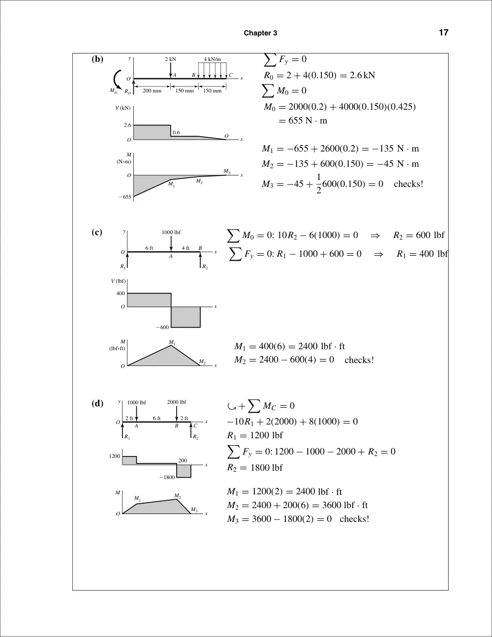
(b)
�
Fy = 0
R0 = 2 + 4(0.150) = 2.6kN
�
M0 = 0
M0 = 2000(0.2) + 4000(0.150)(0.425)
= 655 N · m
M1 = −655 + 2600(0.2) = −135 N · m
M2 = −135 + 600(0.150) = −45 N · m
M3 = −45 + 1
2600(0.150) = 0
checks!
(c)
�
M0 = 0: 10R2 − 6(1000) = 0
⇒
R2 = 600 lbf
�
Fy = 0: R1 − 1000 + 600 = 0
⇒
R1 = 400 lbf
M1 = 400(6) = 2400 lbf · ft
M2 = 2400 − 600(4) = 0
checks!
(d)
�+
�
MC = 0
−10R1 + 2(2000) + 8(1000) = 0
R1 = 1200 lbf
�
Fy = 0: 1200 − 1000 − 2000 + R2 = 0
R2 = 1800 lbf
M1 = 1200(2) = 2400 lbf · ft
M2 = 2400 + 200(6) = 3600 lbf · ft
M3 = 3600 − 1800(2) = 0
checks!
2000 lbf
1000 lbf
R1
O
O
M1
M2
M3
R2
6 ft
2 ft
2 ft
A
B
C
y
M
1200
�1800
200
x
x
x
6 ft
4 ft
A
O
O
O
B
�600
M1
M2
V (lbf)
1000 lbf
y
R1
R2
400
M
(lbf•ft)
x
x
x
V (kN)
150 mm
200 mm
150 mm
2.6
�655
M
(N•m)
0.6
M1
M2
M3
2 kN
4 kN/m
y
A
O
O
O
O
B
C
RO
MO
x
x
x
18
Solutions Manual • Instructor’s Solution Manual to Accompany Mechanical Engineering Design
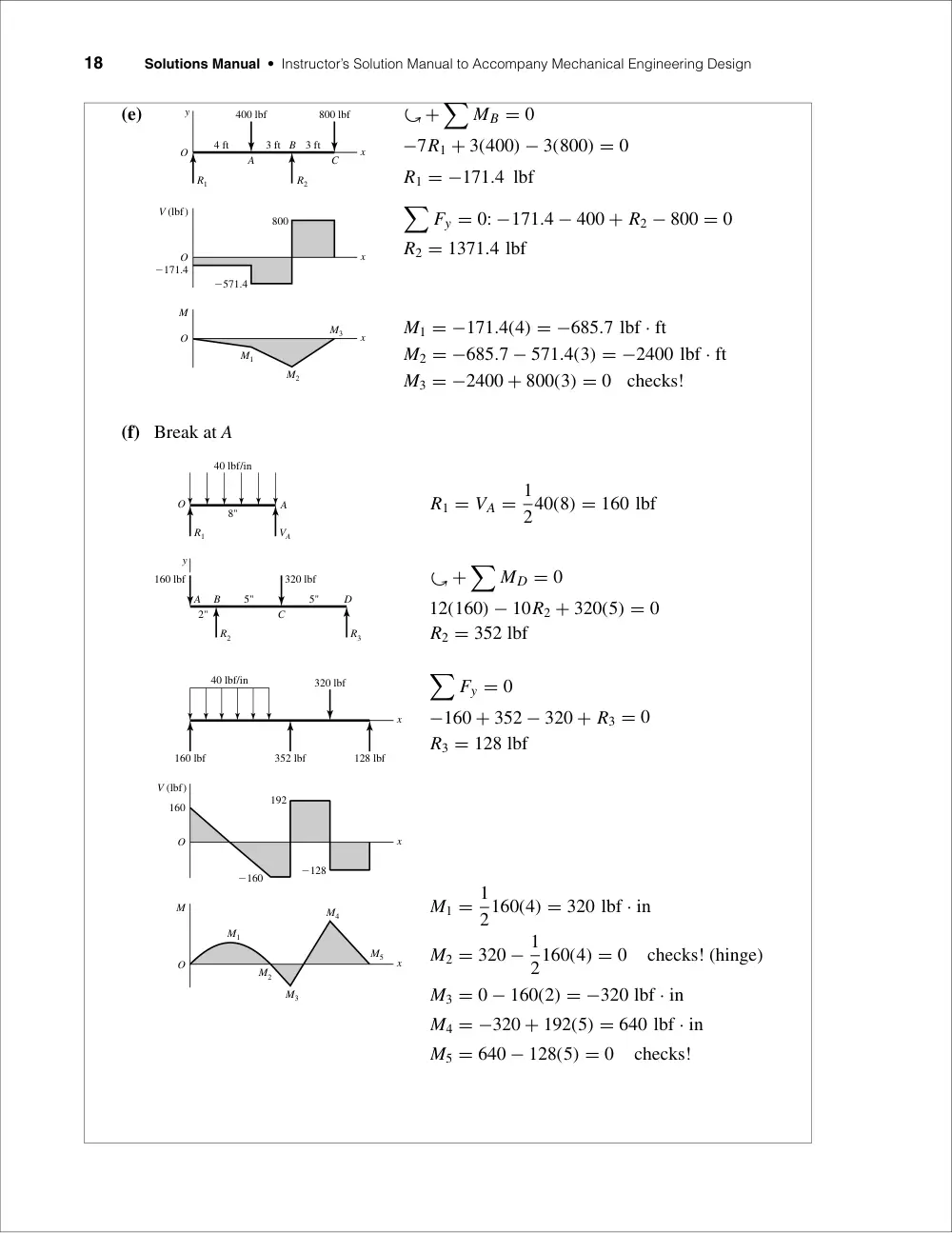
(e)
�+
�
MB = 0
−7R1 + 3(400) − 3(800) = 0
R1 = −171.4 lbf
�
Fy = 0: −171.4 − 400 + R2 − 800 = 0
R2 = 1371.4 lbf
M1 = −171.4(4) = −685.7 lbf · ft
M2 = −685.7 − 571.4(3) = −2400 lbf · ft
M3 = −2400 + 800(3) = 0
checks!
(f) Break at A
R1 = VA = 1
240(8) = 160 lbf
� +
�
MD = 0
12(160) − 10R2 + 320(5) = 0
R2 = 352 lbf
�
Fy = 0
−160 + 352 − 320 + R3 = 0
R3 = 128 lbf
M1 = 1
2160(4) = 320 lbf · in
M2 = 320 − 1
2160(4) = 0
checks! (hinge)
M3 = 0 − 160(2) = −320 lbf · in
M4 = −320 + 192(5) = 640 lbf · in
M5 = 640 − 128(5) = 0
checks!
40 lbf/in
V (lbf)
O
O
160
�160
�128
192
M
320 lbf
160 lbf
352 lbf
128 lbf
M1
M2
M3
M4
M5
x
x
x
8"
5"
2"
5"
40 lbf/in
160 lbf
O
A
y
B
D
C
A
320 lbf
R2
R3
R1
VA
A
O
O
O
C
M
V (lbf)
800
�171.4
�571.4
3 ft
3 ft
4 ft
800 lbf
400 lbf
B
y
M1
M2
M3
R1
R2
x
x
x
Chapter 3
19
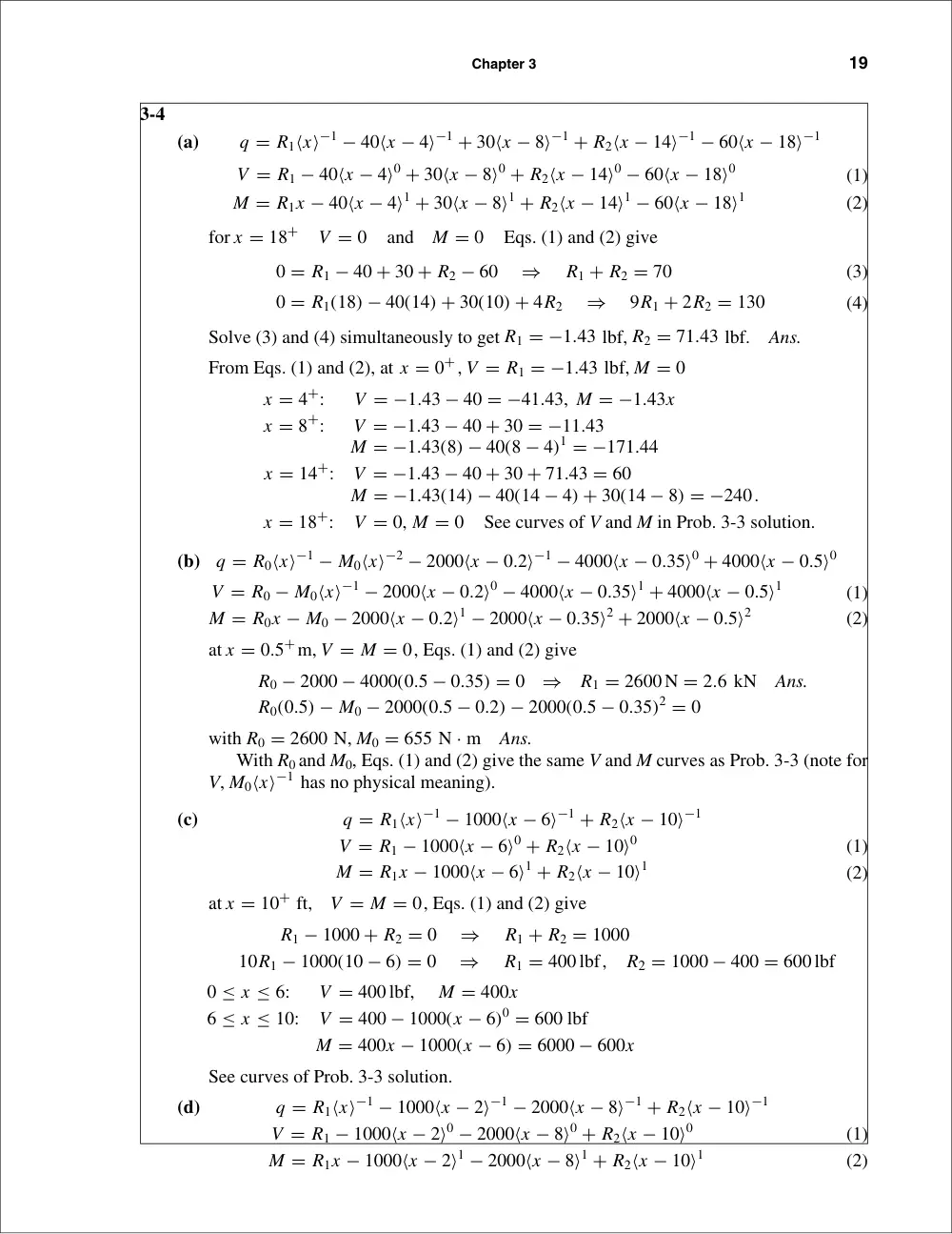
3-4
(a)
q = R1⟨x⟩−1 − 40⟨x − 4⟩−1 + 30⟨x − 8⟩−1 + R2⟨x − 14⟩−1 − 60⟨x − 18⟩−1
V = R1 − 40⟨x − 4⟩0 + 30⟨x − 8⟩0 + R2⟨x − 14⟩0 − 60⟨x − 18⟩0
(1)
M = R1x − 40⟨x − 4⟩1 + 30⟨x − 8⟩1 + R2⟨x − 14⟩1 − 60⟨x − 18⟩1
(2)
for x = 18+
V = 0
and
M = 0
Eqs. (1) and (2) give
0 = R1 − 40 + 30 + R2 − 60
⇒
R1 + R2 = 70
(3)
0 = R1(18) − 40(14) + 30(10) + 4R2
⇒
9R1 + 2R2 = 130
(4)
Solve (3) and (4) simultaneously to get R1 = −1.43 lbf, R2 = 71.43 lbf.
Ans.
From Eqs. (1) and (2), at x = 0+, V = R1 = −1.43 lbf, M = 0
x = 4+:
V = −1.43 − 40 = −41.43, M = −1.43x
x = 8+:
V = −1.43 − 40 + 30 = −11.43
M = −1.43(8) − 40(8 − 4)1 = −171.44
x = 14+:
V = −1.43 − 40 + 30 + 71.43 = 60
M = −1.43(14) − 40(14 − 4) + 30(14 − 8) = −240.
x = 18+:
V = 0, M = 0
See curves of V and M in Prob. 3-3 solution.
(b)
q = R0⟨x⟩−1 − M0⟨x⟩−2 − 2000⟨x − 0.2⟩−1 − 4000⟨x − 0.35⟩0 + 4000⟨x − 0.5⟩0
V = R0 − M0⟨x⟩−1 − 2000⟨x − 0.2⟩0 − 4000⟨x − 0.35⟩1 + 4000⟨x − 0.5⟩1
(1)
M = R0x − M0 − 2000⟨x − 0.2⟩1 − 2000⟨x − 0.35⟩2 + 2000⟨x − 0.5⟩2
(2)
at x = 0.5+m, V = M = 0, Eqs. (1) and (2) give
R0 − 2000 − 4000(0.5 − 0.35) = 0
⇒
R1 = 2600 N = 2.6 kN
Ans.
R0(0.5) − M0 − 2000(0.5 − 0.2) − 2000(0.5 − 0.35)2 = 0
with R0 = 2600 N, M0 = 655 N · m
Ans.
With R0 and M0, Eqs. (1) and (2) give the same V and M curves as Prob. 3-3 (note for
V, M0⟨x⟩−1 has no physical meaning).
(c)
q = R1⟨x⟩−1 − 1000⟨x − 6⟩−1 + R2⟨x − 10⟩−1
V = R1 − 1000⟨x − 6⟩0 + R2⟨x − 10⟩0
(1)
M = R1x − 1000⟨x − 6⟩1 + R2⟨x − 10⟩1
(2)
at x = 10+ ft,
V = M = 0, Eqs. (1) and (2) give
R1 − 1000 + R2 = 0
⇒
R1 + R2 = 1000
10R1 − 1000(10 − 6) = 0
⇒
R1 = 400 lbf,
R2 = 1000 − 400 = 600 lbf
0 ≤ x ≤ 6:
V = 400 lbf,
M = 400x
6 ≤ x ≤ 10:
V = 400 − 1000(x − 6)0 = 600 lbf
M = 400x − 1000(x − 6) = 6000 − 600x
See curves of Prob. 3-3 solution.
(d)
q = R1⟨x⟩−1 − 1000⟨x − 2⟩−1 − 2000⟨x − 8⟩−1 + R2⟨x − 10⟩−1
V = R1 − 1000⟨x − 2⟩0 − 2000⟨x − 8⟩0 + R2⟨x − 10⟩0
(1)
M = R1x − 1000⟨x − 2⟩1 − 2000⟨x − 8⟩1 + R2⟨x − 10⟩1
(2)
20
Solutions Manual • Instructor’s Solution Manual to Accompany Mechanical Engineering Design
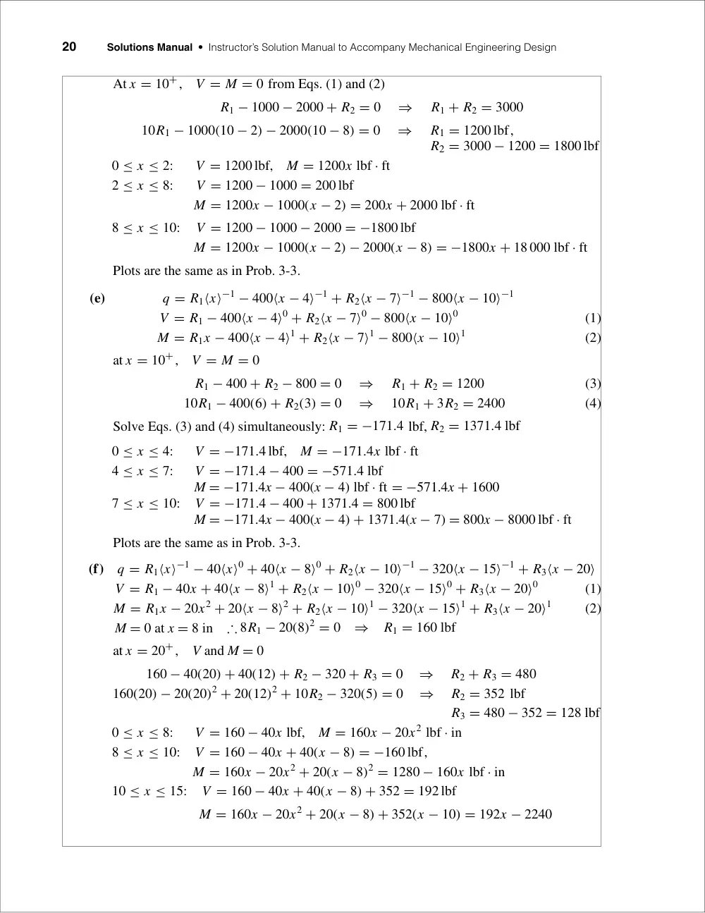
At x = 10+,
V = M = 0 from Eqs. (1) and (2)
R1 − 1000 − 2000 + R2 = 0
⇒
R1 + R2 = 3000
10R1 − 1000(10 − 2) − 2000(10 − 8) = 0
⇒
R1 = 1200 lbf,
R2 = 3000 − 1200 = 1800 lbf
0 ≤ x ≤ 2:
V = 1200 lbf,
M = 1200x lbf · ft
2 ≤ x ≤ 8:
V = 1200 − 1000 = 200 lbf
M = 1200x − 1000(x − 2) = 200x + 2000 lbf · ft
8 ≤ x ≤ 10:
V = 1200 − 1000 − 2000 = −1800 lbf
M = 1200x − 1000(x − 2) − 2000(x − 8) = −1800x + 18 000 lbf · ft
Plots are the same as in Prob. 3-3.
(e)
q = R1⟨x⟩−1 − 400⟨x − 4⟩−1 + R2⟨x − 7⟩−1 − 800⟨x − 10⟩−1
V = R1 − 400⟨x − 4⟩0 + R2⟨x − 7⟩0 − 800⟨x − 10⟩0
(1)
M = R1x − 400⟨x − 4⟩1 + R2⟨x − 7⟩1 − 800⟨x − 10⟩1
(2)
at x = 10+,
V = M = 0
R1 − 400 + R2 − 800 = 0
⇒
R1 + R2 = 1200
(3)
10R1 − 400(6) + R2(3) = 0
⇒
10R1 + 3R2 = 2400
(4)
Solve Eqs. (3) and (4) simultaneously: R1 = −171.4 lbf, R2 = 1371.4 lbf
0 ≤ x ≤ 4:
V = −171.4 lbf,
M = −171.4x lbf · ft
4 ≤ x ≤ 7:
V = −171.4 − 400 = −571.4 lbf
M = −171.4x − 400(x − 4) lbf · ft = −571.4x + 1600
7 ≤ x ≤ 10:
V = −171.4 − 400 + 1371.4 = 800 lbf
M = −171.4x − 400(x − 4) + 1371.4(x − 7) = 800x − 8000 lbf · ft
Plots are the same as in Prob. 3-3.
(f)
q = R1⟨x⟩−1 − 40⟨x⟩0 + 40⟨x − 8⟩0 + R2⟨x − 10⟩−1 − 320⟨x − 15⟩−1 + R3⟨x − 20⟩
V = R1 − 40x + 40⟨x − 8⟩1 + R2⟨x − 10⟩0 − 320⟨x − 15⟩0 + R3⟨x − 20⟩0
(1)
M = R1x − 20x2 + 20⟨x − 8⟩2 + R2⟨x − 10⟩1 − 320⟨x − 15⟩1 + R3⟨x − 20⟩1
(2)
M = 0 at x = 8 in
∴ 8R1 − 20(8)2 = 0
⇒
R1 = 160 lbf
at x = 20+,
V and M = 0
160 − 40(20) + 40(12) + R2 − 320 + R3 = 0
⇒
R2 + R3 = 480
160(20) − 20(20)2 + 20(12)2 + 10R2 − 320(5) = 0
⇒
R2 = 352 lbf
R3 = 480 − 352 = 128 lbf
0 ≤ x ≤ 8:
V = 160 − 40x lbf,
M = 160x − 20x2 lbf · in
8 ≤ x ≤ 10:
V = 160 − 40x + 40(x − 8) = −160 lbf,
M = 160x − 20x2 + 20(x − 8)2 = 1280 − 160x lbf · in
10 ≤ x ≤ 15:
V = 160 − 40x + 40(x − 8) + 352 = 192 lbf
M = 160x − 20x2 + 20(x − 8) + 352(x − 10) = 192x − 2240
Chapter 3
21
15 ≤ x ≤ 20:
V = 160 − 40x + 40(x − 8) + 352 − 320 = −128 lbf
M = 160x − 20x2 − 20(x − 8) + 352(x − 10) − 320(x − 15)
= −128x + 2560
Plots of V and M are the same as in Prob. 3-3.
3-5 Solution depends upon the beam selected.
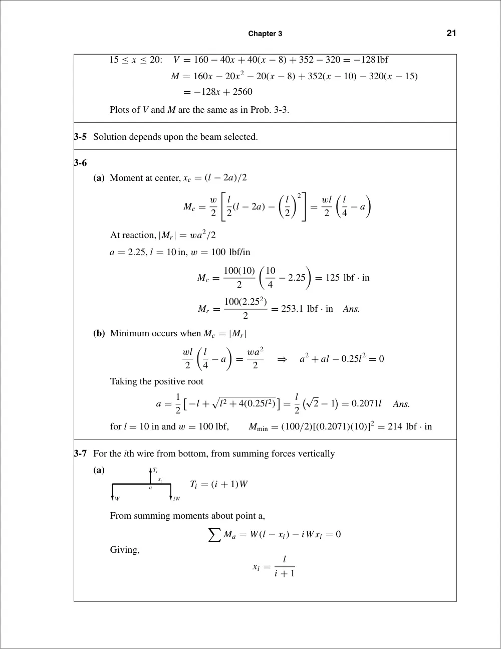
3-6
(a) Moment at center, xc = (l − 2a)/2
Mc = w
2
�
l
2(l − 2a) −
� l
2
�2�
= wl
2
� l
4 − a
�
At reaction, |Mr| = wa2/2
a = 2.25, l = 10 in, w = 100 lbf/in
Mc = 100(10)
2
�10
4 − 2.25
�
= 125 lbf · in
Mr = 100(2.252)
2
= 253.1 lbf · in
Ans.
(b) Minimum occurs when Mc = |Mr|
wl
2
� l
4 − a
�
= wa2
2
⇒
a2 + al − 0.25l2 = 0
Taking the positive root
a = 1
2
�
−l +
�
l2 + 4(0.25l2)
�
= l
2
�√
2 − 1
�
= 0.2071l
Ans.
for l = 10 in and w = 100 lbf,
Mmin = (100/2)[(0.2071)(10)]2 = 214 lbf · in
3-7 For the ith wire from bottom, from summing forces vertically
(a)
Ti = (i + 1)W
From summing moments about point a,
�
Ma = W(l − xi) − iW xi = 0
Giving,
xi =
l
i + 1
W
iW
Ti
xi
a
22
Solutions Manual • Instructor’s Solution Manual to Accompany Mechanical Engineering Design
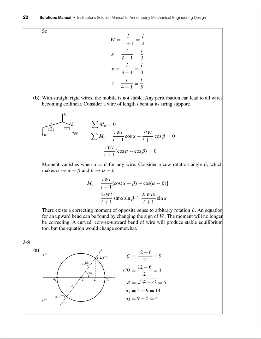
So
W =
l
1 + 1 = l
2
x =
l
2 + 1 = l
3
y =
l
3 + 1 = l
4
z =
l
4 + 1 = l
5
(b) With straight rigid wires, the mobile is not stable. Any perturbation can lead to all wires
becoming collinear. Consider a wire of length l bent at its string support:
�
Ma = 0
�
Ma = iWl
i + 1 cos α − ilW
i + 1 cos β = 0
iWl
i + 1(cos α − cos β) = 0
Moment vanishes when α = β for any wire. Consider a ccw rotation angle β, which
makes α → α + β and β → α − β
Ma = iWl
i + 1[cos(α + β) − cos(α − β)]
= 2iWl
i + 1 sin α sin β .= 2iWlβ
i + 1 sin α
There exists a correcting moment of opposite sense to arbitrary rotation β. An equation
for an upward bend can be found by changing the sign of W. The moment will no longer
be correcting. A curved, convex-upward bend of wire will produce stable equilibrium
too, but the equation would change somewhat.
3-8
(a)
C = 12 + 6
2
= 9
CD = 12 − 6
2
= 3
R =
�
32 + 42 = 5
σ1 = 5 + 9 = 14
σ2 = 9 − 5 = 4
2�s
(12, 4cw)
C
R
D
�2
�1
�1
�
�2
2�p
(6, 4ccw)
y
x
�cw
�ccw
W
iW
il
i � 1
Ti
�
�
l
i � 1
Chapter 3
23
φp = 1
2 tan−1
�4
3
�
= 26.6◦ cw
τ1 = R = 5,
φs = 45◦ − 26.6◦ = 18.4◦ ccw
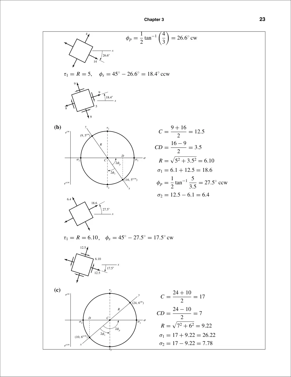
(b)
C = 9 + 16
2
= 12.5
CD = 16 − 9
2
= 3.5
R =
�
52 + 3.52 = 6.10
σ1 = 6.1 + 12.5 = 18.6
φp = 1
2 tan−1 5
3.5 = 27.5◦ ccw
σ2 = 12.5 − 6.1 = 6.4
τ1 = R = 6.10,
φs = 45◦ − 27.5◦ = 17.5◦ cw
(c)
C = 24 + 10
2
= 17
CD = 24 − 10
2
= 7
R =
�
72 + 62 = 9.22
σ1 = 17 + 9.22 = 26.22
σ2 = 17 − 9.22 = 7.78
2�s
(24, 6cw)
C
R
D
�2
�1
�1
�2
2�p
(10, 6ccw)
y
x
�
�cw
�ccw
x
12.5
12.5
6.10
17.5�
x
6.4
18.6
27.5�
2�s
(16, 5ccw)
C
R
D
�2
�1
�1
�2
2�p
(9, 5cw)
y
x
�
�cw
�ccw
9
5
9
9
9
18.4�
x
x
4
14
26.6�
24
Solutions Manual • Instructor’s Solution Manual to Accompany Mechanical Engineering Design
φp = 1
2
�
90 + tan−1 7
6
�
= 69.7◦ ccw
τ1 = R = 9.22,
φs = 69.7◦ − 45◦ = 24.7◦ ccw
(d)
C = 9 + 19
2
= 14
CD = 19 − 9
2
= 5
R =
�
52 + 82 = 9.434
σ1 = 14 + 9.43 = 23.43
σ2 = 14 − 9.43 = 4.57
φp = 1
2
�
90 + tan−1 5
8
�
= 61.0◦ cw
τ1 = R = 9.434,
φs = 61◦ − 45◦ = 16◦ cw
x
14
14
9.434
16�
x
23.43
4.57
61�
2�s
(9, 8cw)
C
R
D
�2
�1
�1
�2
2�p
(19, 8ccw)
y
x
�
�cw
�ccw
x
17
17
9.22
24.7�
x
26.22
7.78
69.7�
Chapter 3
25
3-9
(a)
C = 12 − 4
2
= 4
CD = 12 + 4
2
= 8
R =
�
82 + 72 = 10.63
σ1 = 4 + 10.63 = 14.63
σ2 = 4 − 10.63 = −6.63
φp = 1
2
�
90 + tan−1 8
7
�
= 69.4◦ ccw
τ1 = R = 10.63,
φs = 69.4◦ − 45◦ = 24.4◦ ccw
(b)
C = 6 − 5
2
= 0.5
CD = 6 + 5
2
= 5.5
R =
�
5.52 + 82 = 9.71
σ1 = 0.5 + 9.71 = 10.21
σ2 = 0.5 − 9.71 = −9.21
φp = 1
2 tan−1 8
5.5 = 27.75◦ ccw
x
10.21
9.21
27.75�
2�s
(�5, 8cw)
C
R
D
�2
�1
�1
�
�2
2�p
(6, 8ccw)
y
x
�cw
�ccw
x
4
4
10.63
24.4�
x
14.63
6.63
69.4�
2�s
(12, 7cw)
C
R
D
�2
�1
�1
�
�2
2�p
(�4, 7ccw)
y
x
�cw
�ccw
26
Solutions Manual • Instructor’s Solution Manual to Accompany Mechanical Engineering Design
τ1 = R = 9.71,
φs = 45◦ − 27.75◦ = 17.25◦ cw
(c)
C = −8 + 7
2
= −0.5
CD = 8 + 7
2
= 7.5
R =
�
7.52 + 62 = 9.60
σ1 = 9.60 − 0.5 = 9.10
σ2 = −0.5 − 9.6 = −10.1
φp = 1
2
�
90 + tan−1 7.5
6
�
= 70.67◦ cw
τ1 = R = 9.60,
φs = 70.67◦ − 45◦ = 25.67◦ cw
(d)
C = 9 − 6
2
= 1.5
CD = 9 + 6
2
= 7.5
R =
�
7.52 + 32 = 8.078
σ1 = 1.5 + 8.078 = 9.58
σ2 = 1.5 − 8.078 = −6.58
2�s
(9, 3cw)
C
R
D
�2
�1
�1
�2
2�p
(�6, 3ccw)
y
x
�
�cw
�ccw
x
0.5
0.5
9.60
25.67�
x
10.1
9.1
70.67�
2�s
(�8, 6cw)
C
R
D
�2
�1
�1
�2
2�p
(7, 6ccw)
x
y
�
�cw
�ccw
x
0.5
0.5
9.71
17.25�
Chapter 3
27
φp = 1
2 tan−1 3
7.5 = 10.9◦ cw
τ1 = R = 8.078,
φs = 45◦ − 10.9◦ = 34.1◦ ccw
3-10
(a)
C = 20 − 10
2
= 5
CD = 20 + 10
2
= 15
R =
�
152 + 82 = 17
σ1 = 5 + 17 = 22
σ2 = 5 − 17 = −12
φp = 1
2 tan−1 8
15 = 14.04◦ cw
τ1 = R = 17,
φs = 45◦ − 14.04◦ = 30.96◦ ccw
5
17
5
30.96�
x
12
22
14.04�
x
2�s
(20, 8cw)
C
R
D
�2
�1
�1
�2
2�p
(�10, 8ccw)
y
x
�
�cw
�ccw
x
1.5
8.08
1.5
34.1�
x
6.58
9.58
10.9�
28
Solutions Manual • Instructor’s Solution Manual to Accompany Mechanical Engineering Design
(b)
C = 30 − 10
2
= 10
CD = 30 + 10
2
= 20
R =
�
202 + 102 = 22.36
σ1 = 10 + 22.36 = 32.36
σ2 = 10 − 22.36 = −12.36
φp = 1
2 tan−1 10
20 = 13.28◦ ccw
τ1 = R = 22.36,
φs = 45◦ − 13.28◦ = 31.72◦ cw
(c)
C = −10 + 18
2
= 4
CD = 10 + 18
2
= 14
R =
�
142 + 92 = 16.64
σ1 = 4 + 16.64 = 20.64
σ2 = 4 − 16.64 = −12.64
φp = 1
2
�
90 + tan−1 14
9
�
= 73.63◦ cw
τ1 = R = 16.64,
φs = 73.63◦ − 45◦ = 28.63◦ cw
4
x
16.64
4
28.63�
12.64
20.64
73.63�
x
2�s
(�10, 9cw)
C
R
D
�2
�1
�1
�2
2�p
(18, 9ccw)
y
x
�
�cw
�ccw
10
10
22.36
31.72�
x
12.36
32.36
x
13.28�
2�s
(�10, 10cw)
C
R
D
�2
�1
�1
�
�2
2�p
(30, 10ccw)
y
x
�cw
�ccw
Chapter 3
29
(d)
C = −12 + 22
2
= 5
CD = 12 + 22
2
= 17
R =
�
172 + 122 = 20.81
σ1 = 5 + 20.81 = 25.81
σ2 = 5 − 20.81 = −15.81
φp = 1
2
�
90 + tan−1 17
12
�
= 72.39◦ cw
τ1 = R = 20.81,
φs = 72.39◦ − 45◦ = 27.39◦ cw
3-11
(a)
(b)
C = 0 + 10
2
= 5
CD = 10 − 0
2
= 5
R =
�
52 + 42 = 6.40
σ1 = 5 + 6.40 = 11.40
σ2 = 0,
σ3 = 5 − 6.40 = −1.40
τ1/3 = R = 6.40,
τ1/2 = 11.40
2
= 5.70,
τ2/3 = 1.40
2
= 0.70
�1
�2
�
�3
D
x
y
�
C
R
(0, 4cw)
(10, 4ccw)
�2/3
�1/2
�1/3
�x � �1
�
�3 � �y
�
�2 � 0
�4
10
y
x
�2/3 � 2
�1/2 � 5
�1/3 �
14 � 7
2
5
20.81
5
27.39�
x
15.81
25.81
72.39�
x
2�s
(�12, 12cw)
C
R
D
�2
�1
�1
�2
2�p
(22, 12ccw)
y
x
�
�cw
�ccw
30
Solutions Manual • Instructor’s Solution Manual to Accompany Mechanical Engineering Design
(c)
C = −2 − 8
2
= −5
CD = 8 − 2
2
= 3
R =
�
32 + 42 = 5
σ1 = −5 + 5 = 0,
σ2 = 0
σ3 = −5 − 5 = −10
τ1/3 = 10
2 = 5,
τ1/2 = 0,
τ2/3 = 5
(d)
C = 10 − 30
2
= −10
CD = 10 + 30
2
= 20
R =
�
202 + 102 = 22.36
σ1 = −10 + 22.36 = 12.36
σ2 = 0
σ3 = −10 − 22.36 = −32.36
τ1/3 = 22.36,
τ1/2 = 12.36
2
= 6.18,
τ2/3 = 32.36
2
= 16.18
3-12
(a)
C = −80 − 30
2
= −55
CD = 80 − 30
2
= 25
R =
�
252 + 202 = 32.02
σ1 = 0
σ2 = −55 + 32.02 = −22.98 = −23.0
σ3 = −55 − 32.0 = −87.0
τ1/2 = 23
2 = 11.5,
τ2/3 = 32.0,
τ1/3 = 87
2 = 43.5
�1
(�80, 20cw)
(�30, 20ccw)
C
D
R
�2/3
�1/2
�1/3
�2
�3
x
y
�
�
�1
(�30, 10cw)
(10, 10ccw)
C
D
R
�2/3
�1/2
�
�1/3
�2
�3
�
y
x
�1�2
�
�
�3
(�2, 4cw)
Point is a circle
2 circles
C
D
y
x
(�8, 4ccw)
Chapter 3
31
(b)
C = 30 − 60
2
= −15
CD = 60 + 30
2
= 45
R =
�
452 + 302 = 54.1
σ1 = −15 + 54.1 = 39.1
σ2 = 0
σ3 = −15 − 54.1 = −69.1
τ1/3 = 39.1 + 69.1
2
= 54.1,
τ1/2 = 39.1
2
= 19.6,
τ2/3 = 69.1
2
= 34.6
(c)
C = 40 + 0
2
= 20
CD = 40 − 0
2
= 20
R =
�
202 + 202 = 28.3
σ1 = 20 + 28.3 = 48.3
σ2 = 20 − 28.3 = −8.3
σ3 = σz = −30
τ1/3 = 48.3 + 30
2
= 39.1,
τ1/2 = 28.3,
τ2/3 = 30 − 8.3
2
= 10.9
(d)
C = 50
2 = 25
CD = 50
2 = 25
R =
�
252 + 302 = 39.1
σ1 = 25 + 39.1 = 64.1
σ2 = 25 − 39.1 = −14.1
σ3 = σz = −20
τ1/3 = 64.1 + 20
2
= 42.1,
τ1/2 = 39.1,
τ2/3 = 20 − 14.1
2
= 2.95
�1
(50, 30cw)
(0, 30ccw)
C
D
�2/3
�1/2
�1/3
�2
�3
x
y
�
�
�1
(0, 20cw)
(40, 20ccw)
C
D
R
�2/3
�1/2
�1/3
�2
�3
y
x
�
�
�1
�
�
(�60, 30ccw)
(30, 30cw)
C
D
R
�2/3
�1/2
�1/3
�2
�3
x
y
32
Solutions Manual • Instructor’s Solution Manual to Accompany Mechanical Engineering Design
3-13
σ = F
A =
2000
(π/4)(0.52) = 10 190 psi = 10.19 kpsi
Ans.
δ = FL
AE = σ L
E = 10 190
72
30(106) = 0.024 46 in
Ans.
ϵ1 = δ
L = 0.024 46
72
= 340(10−6) = 340µ
Ans.
From Table A-5, ν = 0.292
ϵ2 = −νϵ1 = −0.292(340) = −99.3µ
Ans.
�d = ϵ2d = −99.3(10−6)(0.5) = −49.6(10−6) in
Ans.
3-14
From Table A-5, E = 71.7 GPa
δ = σ L
E = 135(106)
3
71.7(109) = 5.65(10−3) m = 5.65 mm
Ans.
3-15
With σz = 0, solve the first two equations of Eq. (3-19) simultaneously. Place E on the left-
hand side of both equations, and using Cramer’s rule,
σx =
��� Eϵx
−ν
Eϵy
1
���
��� 1
−ν
−ν
1
���
= Eϵx + νEϵy
1 − ν2
= E(ϵx + νϵy)
1 − ν2
Likewise,
σy = E(ϵy + νϵx)
1 − ν2
From Table A-5, E = 207 GPa and ν = 0.292. Thus,
σx = E(ϵx + νϵy)
1 − ν2
= 207(109)[0.0021 + 0.292(−0.000 67)]
1 − 0.2922
(10−6) = 431 MPa
Ans.
σy = 207(109)[−0.000 67 + 0.292(0.0021)]
1 − 0.2922
(10−6) = −12.9 MPa
Ans.
3-16
The engineer has assumed the stress to be uniform. That is,
�
Ft = −F cos θ + τ A = 0
⇒
τ = F
A cos θ
When failure occurs in shear
Ssu = F
A cos θ
�
�
t
�
F
Chapter 3
33
The uniform stress assumption is common practice but is not exact. If interested in the
details, see p. 570 of 6th edition.
3-17
From Eq. (3-15)
σ 3 − (−2 + 6 − 4)σ 2 + [−2(6) + (−2)(−4) + 6(−4) − 32 − 22 − (−5)2]σ
− [−2(6)(−4) + 2(3)(2)(−5) − (−2)(2)2 − 6(−5)2 − (−4)(3)2] = 0
σ 3 − 66σ + 118 = 0
Roots are: 7.012, 1.89, −8.903 kpsi
Ans.
τ1/2 = 7.012 − 1.89
2
= 2.56 kpsi
τ2/3 = 8.903 + 1.89
2
= 5.40 kpsi
τmax = τ1/3 = 8.903 + 7.012
2
= 7.96 kpsi
Ans.
Note: For Probs. 3-17 to 3-19, one can also find the eigenvalues of the matrix
[σ] =
� σx
τxy
τzx
τxy
σy
τyz
τzx
τyz
σz
�
for the principal stresses
3-18
From Eq. (3-15)
σ 3 − (10 + 0 + 10)σ 2 +
�
10(0) + 10(10) + 0(10) − 202 −
�
−10
√
2
�2 − 02�
σ
−
�
10(0)(10) + 2(20)
�
−10
√
2
�
(0) − 10
�
−10
√
2
�2 − 0(0)2 − 10(20)2�
= 0
σ 3 − 20σ 2 − 500σ + 6000 = 0
Roots are: 30, 10, −20 MPa
Ans.
τ1/2 = 30 − 10
2
= 10 MPa
τ2/3 = 10 + 20
2
= 15 MPa
τmax = τ1/3 = 30 + 20
2
= 25 MPa
Ans.
30
10
�20
�2/3
�1/2
�1/3
� (MPa)
� (MPa)
7.012
1.89
�8.903
�2/3
�1/2
�1/3 � (kpsi)
� (kpsi)
34
Solutions Manual • Instructor’s Solution Manual to Accompany Mechanical Engineering Design
3-19
From Eq. (3-15)
σ 3 − (1 + 4 + 4)σ 2 + [1(4) + 1(4) + 4(4) − 22 − (−4)2 − (−2)2]σ
−[1(4)(4) + 2(2)(−4)(−2) − 1(−4)2 − 4(−2)2 − 4(2)2] = 0
σ 3 − 9σ 2 = 0
Roots are: 9, 0, 0 kpsi
τ2/3 = 0,
τ1/2 = τ1/3 = τmax = 9
2 = 4.5 kpsi
Ans.
3-20
(a) R1 = c
l F
Mmax = R1a = ac
l F
σ = 6M
bh2 =
6
bh2
ac
l F
⇒
F = σbh2l
6ac
Ans.
(b) Fm
F = (σm/σ)(bm/b) (hm/h)2 (lm/l)
(am/a) (cm/c)
= 1(s)(s)2(s)
(s)(s)
= s2
Ans.
For equal stress, the model load varies by the square of the scale factor.
3-21
R1 = wl
2 ,
Mmax|x=l/2 = w
2
l
2
�
l − l
2
�
= wl2
8
σ = 6M
bh2 =
6
bh2
wl2
8
= 3Wl
4bh2
⇒
W = 4
3
σbh2
l
Ans.
Wm
W = (σm/σ)(bm/b) (hm/h)2
lm/l
= 1(s)(s)2
s
= s2
Ans.
wmlm
wl
= s2
⇒
wm
w = s2
s = s
Ans.
For equal stress, the model load w varies linearily with the scale factor.
�2/3
�(kpsi)
�(kpsi)
�1/2 � �1/3
O 0
9
Chapter 3
35
3-22
(a) Can solve by iteration or derive equations for the general case.
Find maximum moment under wheel W3
WT = � W at centroid of W’s
RA = l − x3 − d3
l
WT
Under wheel 3
M3 = RAx3 − W1a13 − W2a23 = (l − x3 − d3)
l
WT x3 − W1a13 − W2a23
For maximum,
dM3
dx3
= 0 = (l − d3 − 2x3) WT
l
⇒
x3 = l − d3
2
substitute into M,
⇒
M3 = (l − d3)2
4l
WT − W1a13 − W2a23
This means the midpoint of d3 intersects the midpoint of the beam
For wheel i
xi = l − di
2
,
Mi = (l − di)2
4l
WT −
i−1
�
j=1
Wjaji
Note for wheel 1: �Wjaji = 0
WT = 104.4,
W1 = W2 = W3 = W4 = 104.4
4
= 26.1 kip
Wheel 1:
d1 = 476
2
= 238 in,
M1 = (1200 − 238)2
4(1200)
(104.4) = 20 128 kip · in
Wheel 2:
d2 = 238 − 84 = 154 in
M2 = (1200 − 154)2
4(1200)
(104.4) − 26.1(84) = 21 605 kip · in = Mmax
Check if all of the wheels are on the rail
(b) xmax = 600 − 77 = 523 in
(c) See above sketch.
(d) inner axles
600"
600"
84" 77"
84"
315"
xmax
RA
W1
A
B
W3
. . .
. . .
W2
WT
d3
Wn
RB
a23
a13
x3
l
36
Solutions Manual • Instructor’s Solution Manual to Accompany Mechanical Engineering Design
3-23
(a)
Aa = Ab = 0.25(1.5) = 0.375 in2
A = 3(0.375) = 1.125 in2
¯y = 2(0.375)(0.75) + 0.375(0.5)
1.125
= 0.667 in
Ia = 0.25(1.5)3
12
= 0.0703 in4
Ib = 1.5(0.25)3
12
= 0.001 95 in4
I1 = 2[0.0703 + 0.375(0.083)2] + [0.001 95 + 0.375(0.167)2] = 0.158 in4
Ans.
σA = 10 000(0.667)
0.158
= 42(10)3 psi
Ans.
σB = 10 000(0.667 − 0.375)
0.158
= 18.5(10)3 psi
Ans.
σC = 10 000(0.167 − 0.125)
0.158
= 2.7(10)3 psi
Ans.
σD = −10 000(0.833)
0.158
= −52.7(10)3 psi
Ans.
(b)
Here we treat the hole as a negative area.
Aa = 1.732 in2
Ab = 1.134
�0.982
2
�
= 0.557 in2
D
C
B
A
y
1
1
a
b
A
Ga
Gb
0.327"
0.25"
c1 � 1.155"
c2 � 0.577"
2"
1.732"
0.577"
0.982"
0.577"
1.134"
1
2
1 "
1
4"
3
8"
1
4"
1
4"
D
C
1
1
Ga
Gb
c1 � 0.833"
0.167"
0.083"
0.5"
0.75"
1.5"
y � c2 � 0.667"
B
a
a
b
A
Chapter 3
37
A = 1.732 − 0.557 = 1.175 in2
¯y = 1.732(0.577) − 0.557(0.577)
1.175
= 0.577 in
Ans.
Ia = bh3
36 = 2(1.732)3
36
= 0.289 in4
Ib = 1.134(0.982)3
36
= 0.0298 in4
I1 = Ia − Ib = 0.289 − 0.0298 = 0.259 in4
Ans.
because the centroids are coincident.
σA = 10 000(0.577)
0.259
= 22.3(10)3 psi
Ans.
σB = 10 000(0.327)
0.259
= 12.6(10)3 psi
Ans.
σC = −10 000(0.982 − 0.327)
0.259
= −25.3(10)3 psi
Ans.
σD = −10 000(1.155)
0.259
= −44.6(10)3 psi
Ans.
(c) Use two negative areas.
Aa = 1 in2,
Ab = 9 in2,
Ac = 16 in2,
A = 16 − 9 − 1 = 6 in2;
¯ya = 0.25 in,
¯yb = 2.0 in,
¯yc = 2 in
¯y = 16(2) − 9(2) − 1(0.25)
6
= 2.292 in
Ans.
c1 = 4 − 2.292 = 1.708 in
Ia = 2(0.5)3
12
= 0.020 83 in4
Ib = 3(3)3
12
= 6.75 in4
Ic = 4(4)3
12
= 21.333 in4
D
C
c
a
B
b
A
Ga
Gb
Gc
c1 � 1.708"
c2 � 2.292" 2"
1.5"
0.25"
1
1
38
Solutions Manual • Instructor’s Solution Manual to Accompany Mechanical Engineering Design
I1 = [21.333 + 16(0.292)2] − [6.75 + 9(0.292)2]
− [0.020 83 + 1(2.292 − 0.25)2]
= 10.99 in4
Ans.
σA = 10 000(2.292)
10.99
= 2086 psi
Ans.
σB = 10 000(2.292 − 0.5)
10.99
= 1631 psi
Ans.
σC = −10 000(1.708 − 0.5)
10.99
= −1099 psi
Ans.
σD = −10 000(1.708)
10.99
= −1554 psi
Ans.
(d) Use a as a negative area.
Aa = 6.928 in2,
Ab = 16 in2,
A = 9.072 in2;
¯ya = 1.155 in,
¯yb = 2 in
¯y = 2(16) − 1.155(6.928)
9.072
= 2.645 in
Ans.
c1 = 4 − 2.645 = 1.355 in
Ia = bh3
36 = 4(3.464)3
36
= 4.618 in4
Ib = 4(4)3
12
= 21.33 in4
I1 = [21.33 + 16(0.645)2] − [4.618 + 6.928(1.490)2]
= 7.99 in4
Ans.
σA = 10 000(2.645)
7.99
= 3310 psi
Ans.
σB = −10 000(3.464 − 2.645)
7.99
= −1025 psi
Ans.
σC = −10 000(1.355)
7.99
= −1696 psi
Ans.
3.464"
1
1
Ga
B
b
a
C
A
c1 � 1.355"
c2 � 2.645"
1.490"
1.155"
Chapter 3
39
(e)
Aa = 6(1.25) = 7.5 in2
Ab = 3(1.5) = 4.5 in2
A = Ac + Ab = 12 in2
¯y = 3.625(7.5) + 1.5(4.5)
12
= 2.828 in
Ans.
I = 1
12(6)(1.25)3 + 7.5(3.625 − 2.828)2 + 1
12(1.5)(3)3 + 4.5(2.828 − 1.5)2
= 17.05 in4
Ans.
σA = 10 000(2.828)
17.05
= 1659 psi
Ans.
σB = −10 000(3 − 2.828)
17.05
= −101 psi
Ans.
σC = −10 000(1.422)
17.05
= −834 psi
Ans.
(f)
Let a = total area
A = 1.5(3) − 1(1.25) = 3.25 in2
I = Ia − 2Ib = 1
12(1.5)(3)3 − 1
12(1.25)(1)3
= 3.271 in4
Ans.
σA = 10 000(1.5)
3.271
= 4586 psi,
σD = −4586 psi
Ans.
σB = 10 000(0.5)
3.271
= 1529 psi,
σC = −1529 psi
3-24
(a) The moment is maximum and constant between A and B
M = −50(20) = −1000 lbf · in,
I = 1
12(0.5)(2)3 = 0.3333 in4
ρ =
����
E I
M
���� = 1.6(106)(0.3333)
1000
= 533.3 in
(x, y) = (30, −533.3) in
Ans.
(b) The moment is maximum and constant between A and B
M = 50(5) = 250 lbf · in,
I = 0.3333 in4
ρ = 1.6(106)(0.3333)
250
= 2133 in
Ans.
(x, y) = (20, 2133) in
Ans.
C
B
A
b
a
b
D
c � 1.5
c � 1.5
1.5
a
b
A
B
C
c1 � 1.422"
c2 � 2.828"
40
Solutions Manual • Instructor’s Solution Manual to Accompany Mechanical Engineering Design
3-25
(a)
I = 1
12(0.75)(1.5)3 = 0.2109 in4
A = 0.75(1.5) = 1.125 in
Mmax is at A. At the bottom of the section,
σmax = Mc
I
= 4000(0.75)
0.2109
= 14 225 psi
Ans.
Due to V, τmax constant is between A and B
at y = 0
τmax = 3
2
V
A = 3
2
667
1.125 = 889 psi
Ans.
(b)
I = 1
12(1)(2)3 = 0.6667 in4
Mmax is at A at the top of the beam
σmax = 8000(1)
0.6667 = 12 000 psi
Ans.
|Vmax| = 1000 lbf
from O to B at y = 0
τmax = 3
2
V
A = 3
2
1000
(2)(1) = 750 psi
Ans.
(c)
I = 1
12(0.75)(2)3 = 0.5 in4
M1 = −1
2600(5) = −1500 lbf · in = M3
M2 = −1500 + 1
2(900)(7.5) = 1875 lbf · in
Mmax is at span center. At the bottom of the
beam,
σmax = 1875(1)
0.5
= 3750 psi
Ans.
At A and B at y = 0
τmax = 3
2
900
(0.75)(2) = 900 psi
Ans.
120 lbf/in
1500 lbf
1500 lbf
O
C
B
A
O
O
V (lbf)
M
(lbf•in)
5"
15"
5"
900
M1
M2
x
M3
�900
�600
600
x
x
1000 lbf
1000 lbf
1000
�1000
�8000
2000 lbf
O
B
A
O
O
8"
8"
V (lbf)
M
(lbf•in)
x
x
x
1000 lbf
4000
333 lbf
667 lbf
O
B
x
A
O
333
667
O
12"
6"
V (lbf)
M
(lbf•in)
x
Chapter 3
41
(d)
I = 1
12(1)(2)3 = 0.6667 in4
M1 = −600
2 (6) = −1800 lbf · in
M2 = −1800 + 1
2750(7.5) = 1013 lbf · in
At A, top of beam
σmax = 1800(1)
0.6667 = 2700 psi
Ans.
At A, y = 0
τmax = 3
2
750
(2)(1) = 563 psi
Ans.
3-26
Mmax = wl2
8
⇒
σmax = wl2c
8I
⇒
w = 8σ I
cl2
(a)
l = 12(12) = 144 in, I = (1/12)(1.5)(9.5)3 = 107.2 in4
w = 8(1200)(107.2)
4.75(1442)
= 10.4 lbf/in
Ans.
(b)
l = 48 in, I = (π/64)(24 − 1.254) = 0.6656 in4
w = 8(12)(103)(0.6656)
1(48)2
= 27.7 lbf/in
Ans.
(c)
l = 48 in, I .= (1/12)(2)(33) − (1/12)(1.625)(2.6253) = 2.051 in4
w = 8(12)(103)(2.051)
1.5(48)2
= 57.0 lbf/in
Ans.
(d) l = 72 in; Table A-6, I = 2(1.24) = 2.48 in4
cmax = 2.158"
w = 8(12)(103)(2.48)
2.158(72)2
= 21.3 lbf/in
Ans.
(e) l = 72 in; Table A-7, I = 3.85 in4
w = 8(12)(103)(3.85)
2(722)
= 35.6 lbf/in
Ans.
(f) l = 72 in, I = (1/12)(1)(43) = 5.333 in4
w = 8(12)(103)(5.333)
(2)(72)2
= 49.4 lbf/in
Ans.
2
0.842"
2.158"
100 lbf/in
1350 lbf
450 lbf
O
B
A
O
O
V (lbf)
M
(lbf•in)
6"
12"
7.5"
750
M1
M2
�450
�600
x
x
x
42
Solutions Manual • Instructor’s Solution Manual to Accompany Mechanical Engineering Design
3-27
(a) Model (c)
I = π
64(0.54) = 3.068(10−3) in4
A = π
4 (0.52) = 0.1963 in2
σ = Mc
I
= 218.75(0.25)
3.068(10−3)
= 17 825 psi = 17.8 kpsi
Ans.
τmax = 4
3
V
A = 4
3
500
0.1963 = 3400 psi
Ans.
(b) Model (d)
Mmax = 500(0.25) + 1
2(500)(0.375)
= 218.75 lbf · in
Vmax = 500 lbf
Same M and V
∴ σ = 17.8 kpsi
Ans.
τmax = 3400 psi
Ans.
3-28
q = −F⟨x⟩−1 + p1⟨x − l⟩0 − p1 + p2
a
⟨x − l⟩1 + terms for x > l + a
V = −F + p1⟨x − l⟩1 − p1 + p2
2a
⟨x − l⟩2 + terms for x > l + a
M = −Fx + p1
2 ⟨x − l⟩2 − p1 + p2
6a
⟨x − l⟩3 + terms for x > l + a
At x = (l + a)+, V = M = 0, terms for x > l + a = 0
−F + p1a − p1 + p2
2a
a2 = 0
⇒
p1 − p2 = 2F
a
(1)
l
p2
p1
a
b
F
1.25"
500 lbf
500 lbf
0.25"
1333 lbf/in
500
�500
O
V (lbf)
O
M
Mmax
1.25 in
500 lbf
500 lbf
500 lbf
500 lbf
0.4375
500
�500
O
V (lbf)
O
M
(lbf•in)
Mmax � 500(0.4375)
� 218.75 lbf•in
Chapter 3
43
−F(l + a) + p1a2
2
− p1 + p2
6a
a3 = 0
⇒
2p1 − p2 = 6F(l + a)
a2
(2)
From (1) and (2)
p1 = 2F
a2 (3l + 2a),
p2 = 2F
a2 (3l + a)
(3)
From similar triangles
b
p2
=
a
p1 + p2
⇒
b =
ap2
p1 + p2
(4)
Mmax occurs where V = 0
xmax = l + a − 2b
Mmax = −F(l + a − 2b) + p1
2 (a − 2b)2 − p1 + p2
6a
(a − 2b)3
= −Fl − F(a − 2b) + p1
2 (a − 2b)2 − p1 + p2
6a
(a − 2b)3
Normally Mmax = −Fl
The fractional increase in the magnitude is
� = F(a − 2b) − ( p1/2)(a − 2b)2 − [( p1 + p2)/6a](a − 2b)3
Fl
(5)
For example, consider F = 1500 lbf, a = 1.2 in, l = 1.5 in
(3)
p1 = 2(1500)
1.22
[3(1.5) + 2(1.2)] = 14 375 lbf/in
p2 = 2(1500)
1.22
[3(1.5) + 1.2] = 11 875 lbf/in
(4)
b = 1.2(11 875)/(14 375 + 11 875) = 0.5429 in
Substituting into (5) yields
� = 0.036 89
or
3.7% higher than −Fl
a � 2b
l
F
p2
p2
p1
p2
b
b
3-29
R1 = 600(15)
2
+ 20
153000 = 8500 lbf
R2 = 600(15)
2
− 5
153000 = 3500 lbf
a = 3500
600 = 5.833 ft
(a)
¯y = 1(12) + 5(12)
24
= 3 in
Iz = 1
3[2(53) + 6(33) − 4(13)] = 136 in4
At x = 5 ft,
y = −3 in,
σx = −−15000(12)(−3)
136
= −3970 psi
y = 5 in,
σx = −−15000(12)5
136
= 6620 psi
At x = 14.17 ft,
y = −3 in,
σx = −20420(12)(−3)
136
= 5405 psi
y = 5 in,
σx = −20420(12)5
136
= −9010 psi
Max tension = 6620 psi
Ans.
Max compression = −9010 psi
Ans.
(b) Vmax = 5500 lbf
Qn.a. = ¯yA = 2.5(5)(2) = 25 in3
τmax = V Q
Ib = 5500(25)
136(2)
= 506 psi
Ans.
(c) τmax = |σmax|
2
= 9010
2
= 4510 psi
Ans.
z
5 in
44
Solutions Manual • Instructor’s Solution Manual to Accompany Mechanical Engineering Design
600 lbf/ft
3000 lbf
O
O
V (lbf)
M
(lbf•ft)
5'
15'
R1
R2
�3000
�3500
3500(5.833) � 20420
�15000
5500
x
y
x
x
a
z
y
y
V
3-30
R1 = c
l F
M = c
l Fx
0 ≤ x ≤ a
σ = 6M
bh2 = 6(c/l)Fx
bh2
⇒
h =
�
6cFx
blσmax
0 ≤ x ≤ a
Ans.
3-31
From Prob. 3-30, R1 = c
l F = V,
0 ≤ x ≤ a
τmax = 3
2
V
bh = 3
2
(c/l)F
bh
∴ h = 3
2
Fc
lbτmax
Ans.
From Prob. 3-30 =
�
6Fcx
lbσmax
sub in x = e and equate to h above
3
2
Fc
lbτmax
=
�
6Fce
lbσmax
e = 3
8
Fcσmax
lbτ 2max
Ans.
3-32
R1 = b
l F
M = b
l Fx
σmax = 32M
πd3 = 32
πd3
b
l Fx
d =
�32
π
bFx
lσmax
�1/3
0 ≤ x ≤ a
Ans.
3-33
Square:
Am = (b − t)2
Tsq = 2Amtτall = 2(b − t)2tτall
Round:
Am = π(b − t)2/4
Trd = 2π(b − t)2tτall/4
t
b
t
b
R1
F
a
b
l
R2
x
y
R1
R2
F
a
c
l
h(x)
x
e
h
Chapter 3
45
46
Solutions Manual • Instructor’s Solution Manual to Accompany Mechanical Engineering Design
Ratio of torques
Tsq
Trd
=
2(b − t)2tτall
π(b − t)2tτall/2 = 4
π = 1.27
Twist per unit length
square:
θsq = 2Gθ1t
tτall
� L
A
�
m
= C
����
L
A
����
m
= C 4(b − t)
(b − t)2
Round:
θrd = C
� L
A
�
m
= C
π(b − t)
π(b − t)2/4 = C 4(b − t)
(b − t)2
Ratio equals 1, twists are the same.
Note the weight ratio is
Wsq
Wrd
=
ρl(b − t)2
ρlπ(b − t)(t) = b − t
πt
thin-walled assumes b ≥ 20t
= 19
π = 6.04
with b = 20t
= 2.86
with b = 10t
3-34
l = 40 in, τall = 11 500 psi, G = 11.5(106) psi, t = 0.050 in
rm = ri + t/2 = ri + 0.025
for ri > 0
= 0
for ri = 0
Am = (1 − 0.05)2 − 4
�
r2
m − π
4 r2
m
�
= 0.952 − (4 − π)r2
m
Lm = 4(1 − 0.05 − 2rm + 2πrm/4) = 4[0.95 − (2 − π/2)rm]
Eq. (3-45):
T = 2Amtτ = 2(0.05)(11 500)Am = 1150Am
Eq. (3-46):
θ(deg) = θ1 l 180
π
= T Lml
4G A2mt
180
π
=
T Lm(40)
4(11.5)(106)A2m(0.05)
180
π
= 9.9645(10−4) T Lm
A2m
Equations can then be put into a spreadsheet resulting in:
ri
rm
Am
Lm
ri
T(lbf · in)
ri
θ(deg)
0
0
0.902 5
3.8
0
1037.9
0
4.825
0.10
0.125
0.889 087
3.585398
0.10
1022.5
0.10
4.621
0.20
0.225
0.859 043
3.413717
0.20
987.9
0.20
4.553
0.30
0.325
0.811 831
3.242035
0.30
933.6
0.30
4.576
0.40
0.425
0.747 450
3.070354
0.40
859.6
0.40
4.707
0.45
0.475
0.708 822
2.984513
0.45
815.1
0.45
4.825
Chapter 3
47
Torque carrying capacity reduces with ri. However, this is based on an assumption of uni-
form stresses which is not the case for small ri. Also note that weight also goes down with
an increase in ri.
3-35
From Eq. (3-47) where θ1 is the same for each leg.
T1 = 1
3Gθ1L1c3
1,
T2 = 1
3Gθ1L2c3
2
T = T1 + T2 = 1
3Gθ1
�
L1c3
1 + L2c3
2
�
= 1
3Gθ1
�
Lic3
i
Ans.
τ1 = Gθ1c1,
τ2 = Gθ1c2
τmax = Gθ1cmax
Ans.
3-36
(a)
τmax = Gθ1cmax
Gθ1 = τmax
cmax
= 12 000
1/8
= 9.6(104) psi/in
T1/16 = 1
3Gθ1(Lc3)1/16 = 1
3(9.6)(104)(5/8)(1/16)3 = 4.88 lbf · in
Ans.
ri (in)
� (deg)
4.50
4.55
4.65
4.60
4.70
4.75
4.80
4.85
0
0.3
0.2
0.1
0.4
0.5
ri (in)
T (lbf•in)
0
400
200
600
800
1000
1200
0
0.3
0.2
0.1
0.4
0.5
48
Solutions Manual • Instructor’s Solution Manual to Accompany Mechanical Engineering Design
T1/8 = 1
3(9.6)(104)(