
MECH 420 Problems Problem Chap 5, Fall 2012
American University of Beirut · Mechanical Design · 32 pages


Showing the first 10 of 32 pages. Download the PDF to see all of it.
More MECH 420 files
- Problems Chap 4 · Fall 2012ProblemsView
- Problems Chap 6 · Fall 2012ProblemsView
- Problems Chap 7 · Fall 2012ProblemsView
- Problems Chap 8 · Fall 2012ProblemsView
- Problems Chap 9 · Fall 2012ProblemsView
- Problems Problem Chap 1 · Fall 2012ProblemsView
- Problems Problem Chap 2 · Fall 2012ProblemsView
- Problems Problem Chap 3 · Fall 2012ProblemsView
Show the text of this problems
Chapter 5
5-1
MSS:
σ1 − σ3 = Sy/n
⇒
n =
Sy
σ1 − σ3
DE:
n = Sy
σ ′
σ ′ =
�
σ 2
A − σAσB + σ 2
B
�1/2 =
�
σ 2
x − σxσy + σ 2
y + 3τ 2
xy
�1/2
(a) MSS:
σ1 = 12, σ2 = 6, σ3 = 0 kpsi
n = 50
12 = 4.17
Ans.
DE:
σ ′ = (122 − 6(12) + 62)1/2 = 10.39 kpsi,
n =
50
10.39 = 4.81
Ans.
(b) σA, σB = 12
2 ±
��12
2
�2
+ (−8)2 = 16, −4 kpsi
σ1 = 16, σ2 = 0, σ3 = −4 kpsi
MSS:
n =
50
16 − (−4) = 2.5
Ans.
DE:
σ ′ = (122 + 3(−82))1/2 = 18.33 kpsi,
n =
50
18.33 = 2.73
Ans.
(c) σA, σB = −6 − 10
2
±
��−6 + 10
2
�2
+ (−5)2 = −2.615, −13.385 kpsi
σ1 = 0, σ2 = −2.615, σ3 = −13.385 kpsi
MSS:
n =
50
0 − (−13.385) = 3.74
Ans.
DE:
σ ′ = [(−6)2 − (−6)(−10) + (−10)2 + 3(−5)2]1/2
= 12.29 kpsi
n =
50
12.29 = 4.07
Ans.
(d) σA, σB = 12 + 4
2
±
��12 − 4
2
�2
+ 12 = 12.123, 3.877 kpsi
σ1 = 12.123, σ2 = 3.877, σ3 = 0 kpsi
MSS:
n =
50
12.123 − 0 = 4.12
Ans.
DE:
σ ′ = [122 − 12(4) + 42 + 3(12)]1/2 = 10.72 kpsi
n =
50
10.72 = 4.66
Ans.
�B
�A
116
Solutions Manual • Instructor’s Solution Manual to Accompany Mechanical Engineering Design
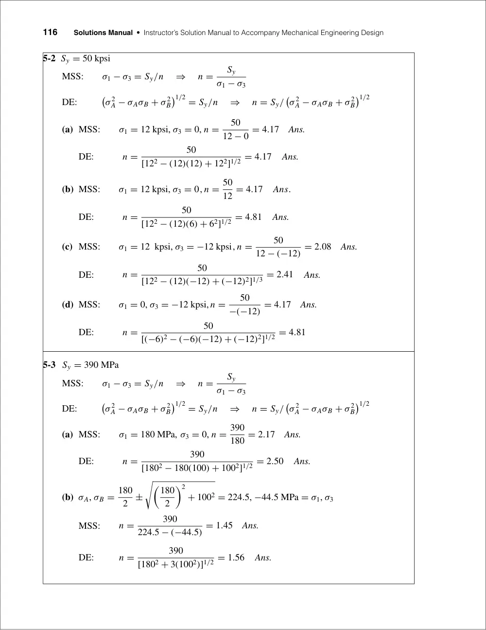
5-2 Sy = 50 kpsi
MSS:
σ1 − σ3 = Sy/n
⇒
n =
Sy
σ1 − σ3
DE:
�
σ 2
A − σAσB + σ 2
B
�1/2 = Sy/n
⇒
n = Sy/
�
σ 2
A − σAσB + σ 2
B
�1/2
(a) MSS:
σ1 = 12 kpsi, σ3 = 0, n =
50
12 − 0 = 4.17
Ans.
DE:
n =
50
[122 − (12)(12) + 122]1/2 = 4.17
Ans.
(b) MSS:
σ1 = 12 kpsi, σ3 = 0, n = 50
12 = 4.17
Ans.
DE:
n =
50
[122 − (12)(6) + 62]1/2 = 4.81
Ans.
(c) MSS:
σ1 = 12 kpsi, σ3 = −12 kpsi, n =
50
12 − (−12) = 2.08
Ans.
DE:
n =
50
[122 − (12)(−12) + (−12)2]1/3 = 2.41
Ans.
(d) MSS:
σ1 = 0, σ3 = −12 kpsi, n =
50
−(−12) = 4.17
Ans.
DE:
n =
50
[(−6)2 − (−6)(−12) + (−12)2]1/2 = 4.81
5-3 Sy = 390 MPa
MSS:
σ1 − σ3 = Sy/n
⇒
n =
Sy
σ1 − σ3
DE:
�
σ 2
A − σAσB + σ 2
B
�1/2 = Sy/n
⇒
n = Sy/
�
σ 2
A − σAσB + σ 2
B
�1/2
(a) MSS:
σ1 = 180 MPa, σ3 = 0, n = 390
180 = 2.17
Ans.
DE:
n =
390
[1802 − 180(100) + 1002]1/2 = 2.50
Ans.
(b) σA, σB = 180
2
±
��180
2
�2
+ 1002 = 224.5, −44.5 MPa = σ1, σ3
MSS:
n =
390
224.5 − (−44.5) = 1.45
Ans.
DE:
n =
390
[1802 + 3(1002)]1/2 = 1.56
Ans.
Chapter 5
117
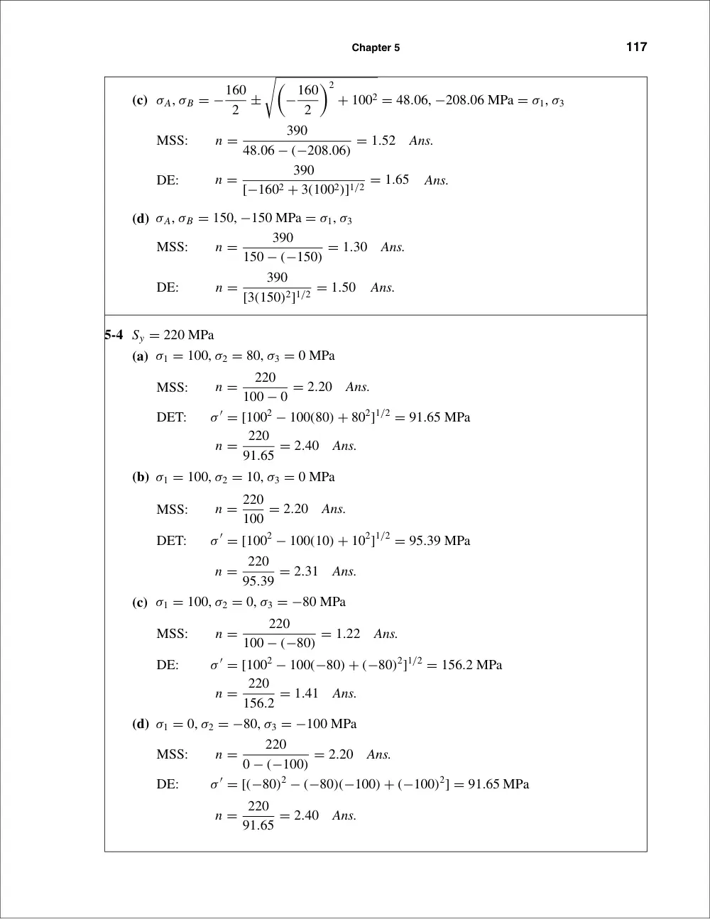
(c) σA, σB = −160
2
±
��
−160
2
�2
+ 1002 = 48.06, −208.06 MPa = σ1, σ3
MSS:
n =
390
48.06 − (−208.06) = 1.52
Ans.
DE:
n =
390
[−1602 + 3(1002)]1/2 = 1.65
Ans.
(d) σA, σB = 150, −150 MPa = σ1, σ3
MSS:
n =
390
150 − (−150) = 1.30
Ans.
DE:
n =
390
[3(150)2]1/2 = 1.50
Ans.
5-4 Sy = 220 MPa
(a) σ1 = 100, σ2 = 80, σ3 = 0 MPa
MSS:
n =
220
100 − 0 = 2.20
Ans.
DET:
σ ′ = [1002 − 100(80) + 802]1/2 = 91.65 MPa
n = 220
91.65 = 2.40
Ans.
(b) σ1 = 100, σ2 = 10, σ3 = 0 MPa
MSS:
n = 220
100 = 2.20
Ans.
DET:
σ ′ = [1002 − 100(10) + 102]1/2 = 95.39 MPa
n = 220
95.39 = 2.31
Ans.
(c) σ1 = 100, σ2 = 0, σ3 = −80 MPa
MSS:
n =
220
100 − (−80) = 1.22
Ans.
DE:
σ ′ = [1002 − 100(−80) + (−80)2]1/2 = 156.2 MPa
n = 220
156.2 = 1.41
Ans.
(d) σ1 = 0, σ2 = −80, σ3 = −100 MPa
MSS:
n =
220
0 − (−100) = 2.20
Ans.
DE:
σ ′ = [(−80)2 − (−80)(−100) + (−100)2] = 91.65 MPa
n = 220
91.65 = 2.40
Ans.
118
Solutions Manual • Instructor’s Solution Manual to Accompany Mechanical Engineering Design
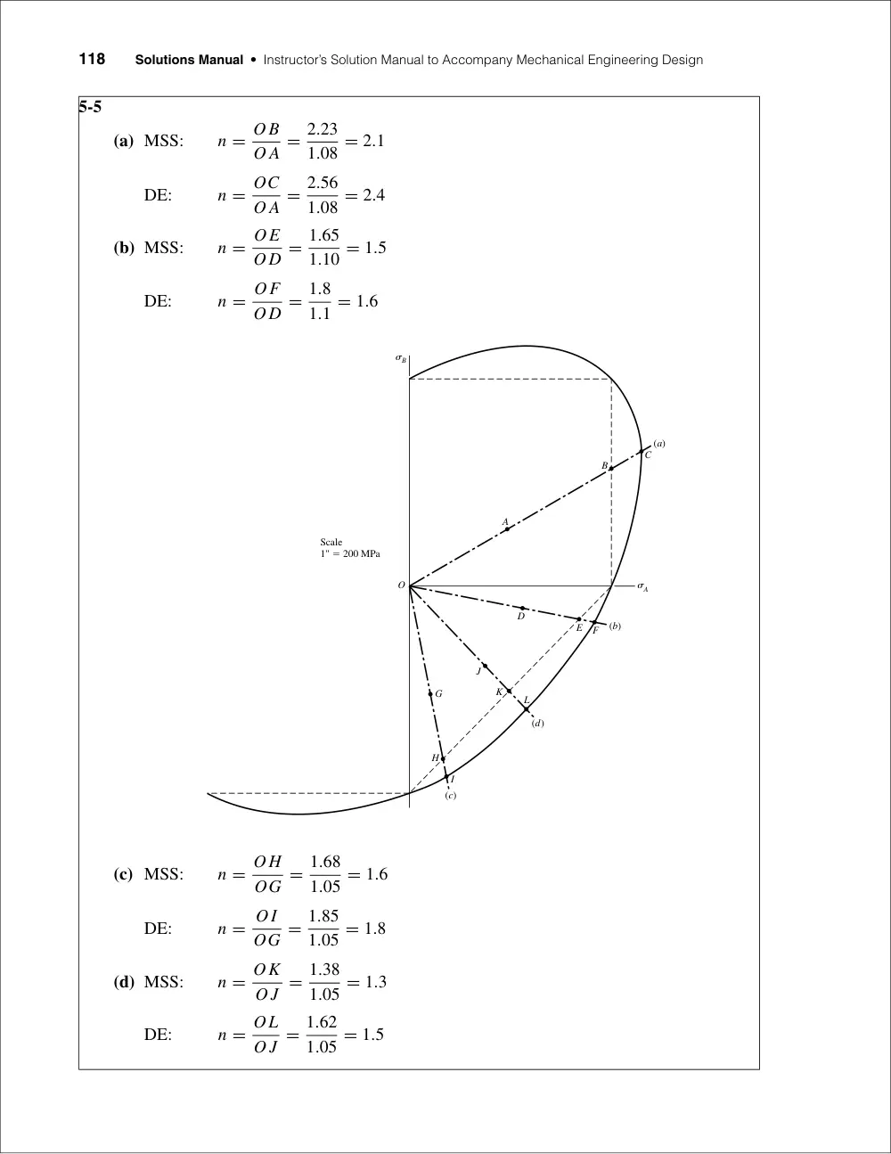
5-5
(a) MSS:
n = O B
O A = 2.23
1.08 = 2.1
DE:
n = OC
O A = 2.56
1.08 = 2.4
(b) MSS:
n = OE
O D = 1.65
1.10 = 1.5
DE:
n = OF
O D = 1.8
1.1 = 1.6
(c) MSS:
n = O H
OG = 1.68
1.05 = 1.6
DE:
n = OI
OG = 1.85
1.05 = 1.8
(d) MSS:
n = OK
O J = 1.38
1.05 = 1.3
DE:
n = OL
O J = 1.62
1.05 = 1.5
O
(a)
(b)
(d)
(c)
H
I
G
J
K
L
F
E
D
A
B
C
Scale
1" � 200 MPa
�B
�A
Chapter 5
119
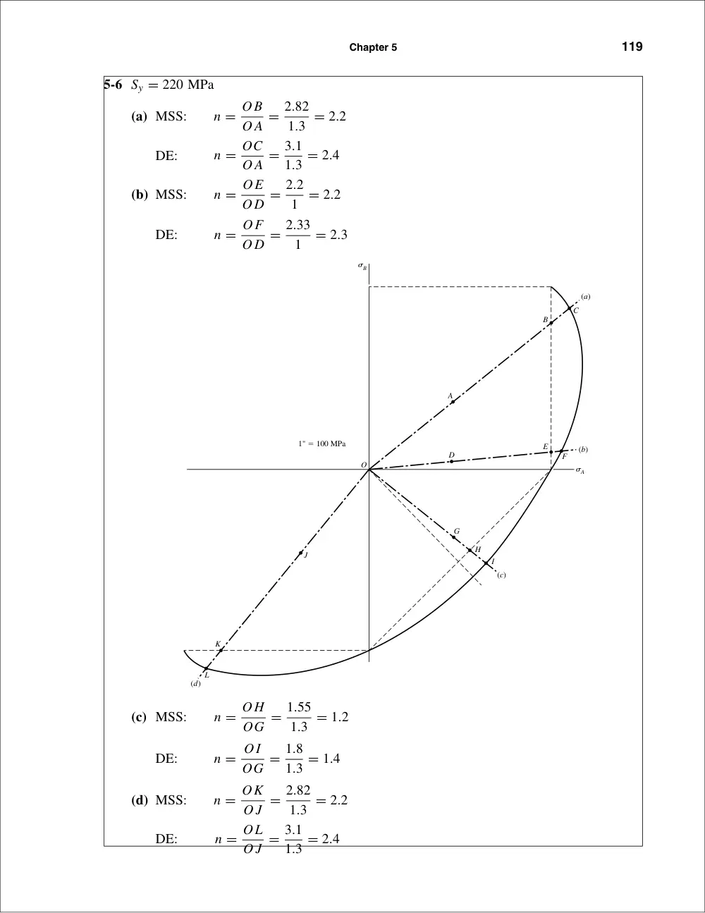
5-6 Sy = 220 MPa
(a) MSS:
n = O B
O A = 2.82
1.3 = 2.2
DE:
n = OC
O A = 3.1
1.3 = 2.4
(b) MSS:
n = OE
O D = 2.2
1 = 2.2
DE:
n = OF
O D = 2.33
1
= 2.3
(c) MSS:
n = O H
OG = 1.55
1.3 = 1.2
DE:
n = OI
OG = 1.8
1.3 = 1.4
(d) MSS:
n = OK
O J = 2.82
1.3 = 2.2
DE:
n = OL
O J = 3.1
1.3 = 2.4
�B
�A
O
(a)
(b)
(c)
(d)
H
G
J
K
L
I
F
E
D
A
B
C
1" � 100 MPa
120
Solutions Manual • Instructor’s Solution Manual to Accompany Mechanical Engineering Design
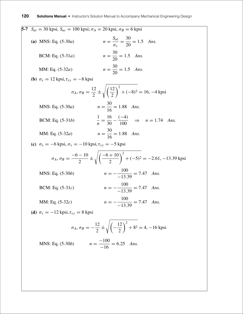
5-7 Sut = 30 kpsi, Suc = 100 kpsi; σA = 20 kpsi, σB = 6 kpsi
(a) MNS: Eq. (5-30a)
n = Sut
σx
= 30
20 = 1.5
Ans.
BCM: Eq. (5-31a)
n = 30
20 = 1.5
Ans.
MM: Eq. (5-32a)
n = 30
20 = 1.5
Ans.
(b) σx = 12 kpsi,τxy = −8 kpsi
σA, σB = 12
2 ±
��12
2
�2
+ (−8)2 = 16, −4 kpsi
MNS: Eq. (5-30a)
n = 30
16 = 1.88
Ans.
BCM: Eq. (5-31b)
1
n = 16
30 − (−4)
100
⇒
n = 1.74
Ans.
MM: Eq. (5-32a)
n = 30
16 = 1.88
Ans.
(c) σx = −6 kpsi, σy = −10 kpsi,τxy = −5 kpsi
σA, σB = −6 − 10
2
±
��−6 + 10
2
�2
+ (−5)2 = −2.61, −13.39 kpsi
MNS: Eq. (5-30b)
n = −
100
−13.39 = 7.47
Ans.
BCM: Eq. (5-31c)
n = −
100
−13.39 = 7.47
Ans.
MM: Eq. (5-32c)
n = −
100
−13.39 = 7.47
Ans.
(d) σx = −12 kpsi,τxy = 8 kpsi
σA, σB = −12
2 ±
��
−12
2
�2
+ 82 = 4, −16 kpsi
MNS: Eq. (5-30b)
n = −100
−16 = 6.25
Ans.
Chapter 5
121
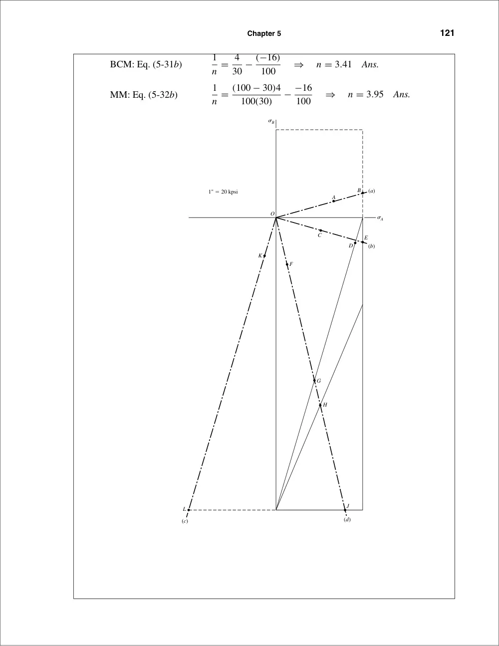
BCM: Eq. (5-31b)
1
n = 4
30 − (−16)
100
⇒
n = 3.41
Ans.
MM: Eq. (5-32b)
1
n = (100 − 30)4
100(30)
− −16
100
⇒
n = 3.95
Ans.
(c)
L
(d)
J
(b)
(a)
H
G
K
F
O
C
D
E
A
B
1" � 20 kpsi
�B
�A
122
Solutions Manual • Instructor’s Solution Manual to Accompany Mechanical Engineering Design
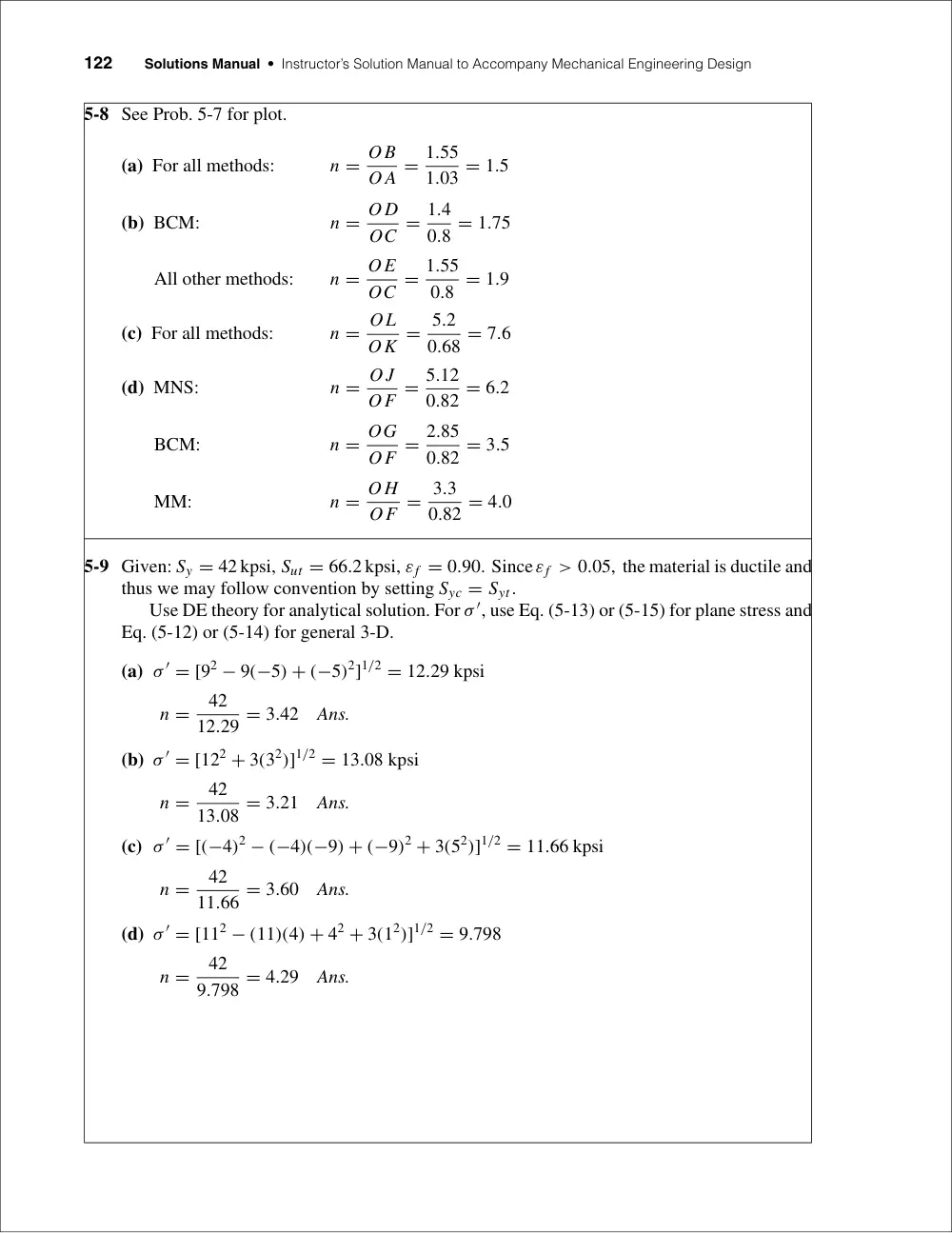
5-8 See Prob. 5-7 for plot.
(a) For all methods:
n = O B
O A = 1.55
1.03 = 1.5
(b) BCM:
n = O D
OC = 1.4
0.8 = 1.75
All other methods:
n = OE
OC = 1.55
0.8 = 1.9
(c) For all methods:
n = OL
OK = 5.2
0.68 = 7.6
(d) MNS:
n = O J
OF = 5.12
0.82 = 6.2
BCM:
n = OG
OF = 2.85
0.82 = 3.5
MM:
n = O H
OF = 3.3
0.82 = 4.0
5-9 Given: Sy = 42 kpsi, Sut = 66.2 kpsi, εf = 0.90. Since εf > 0.05, the material is ductile and
thus we may follow convention by setting Syc = Syt.
Use DE theory for analytical solution. For σ ′, use Eq. (5-13) or (5-15) for plane stress and
Eq. (5-12) or (5-14) for general 3-D.
(a) σ ′ = [92 − 9(−5) + (−5)2]1/2 = 12.29 kpsi
n =
42
12.29 = 3.42
Ans.
(b) σ ′ = [122 + 3(32)]1/2 = 13.08 kpsi
n =
42
13.08 = 3.21
Ans.
(c) σ ′ = [(−4)2 − (−4)(−9) + (−9)2 + 3(52)]1/2 = 11.66 kpsi
n =
42
11.66 = 3.60
Ans.
(d) σ ′ = [112 − (11)(4) + 42 + 3(12)]1/2 = 9.798
n =
42
9.798 = 4.29
Ans.
Chapter 5
123
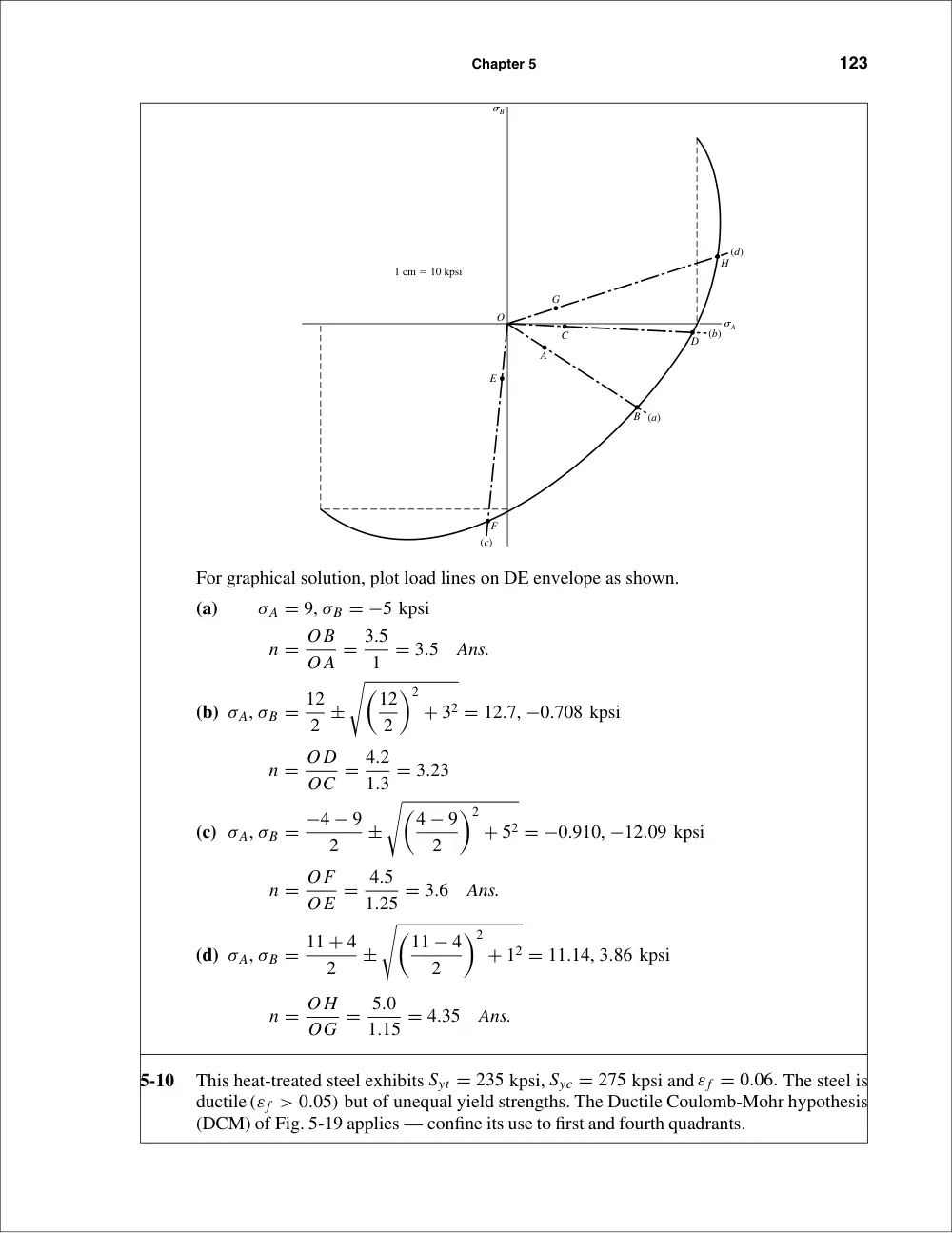
For graphical solution, plot load lines on DE envelope as shown.
(a)
σA = 9, σB = −5 kpsi
n = O B
O A = 3.5
1 = 3.5
Ans.
(b) σA, σB = 12
2 ±
��12
2
�2
+ 32 = 12.7, −0.708 kpsi
n = O D
OC = 4.2
1.3 = 3.23
(c) σA, σB = −4 − 9
2
±
��4 − 9
2
�2
+ 52 = −0.910, −12.09 kpsi
n = OF
OE = 4.5
1.25 = 3.6
Ans.
(d) σA, σB = 11 + 4
2
±
��11 − 4
2
�2
+ 12 = 11.14, 3.86 kpsi
n = O H
OG = 5.0
1.15 = 4.35
Ans.
5-10
This heat-treated steel exhibits Syt = 235 kpsi, Syc = 275 kpsi and εf = 0.06. The steel is
ductile (εf > 0.05) but of unequal yield strengths. The Ductile Coulomb-Mohr hypothesis
(DCM) of Fig. 5-19 applies — confine its use to first and fourth quadrants.
(c)
(a)
(b)
(d)
E
C
G
H
D
B
A
O
F
1 cm � 10 kpsi
�B
�A
124
Solutions Manual • Instructor’s Solution Manual to Accompany Mechanical Engineering Design
(a) σx = 90 kpsi, σy = −50 kpsi, σz = 0 � σA = 90 kpsi and σB = −50 kpsi. For the
fourth quadrant, from Eq. (5-31b)
n =
1
(σA/Syt) − (σB/Suc) =
1
(90/235) − (−50/275) = 1.77
Ans.
(b) σx = 120 kpsi, τxy = −30 kpsi ccw. σA, σB = 127.1, −7.08 kpsi. For the fourth
quadrant
n =
1
(127.1/235) − (−7.08/275) = 1.76
Ans.
(c) σx = −40 kpsi, σy = −90 kpsi, τxy = 50 kpsi.
σA, σB = −9.10, −120.9 kpsi.
Although no solution exists for the third quadrant, use
n = −Syc
σy
= −
275
−120.9 = 2.27
Ans.
(d) σx = 110 kpsi, σy = 40 kpsi, τxy = 10 kpsi cw.
σA, σB = 111.4, 38.6 kpsi. For the
first quadrant
n = Syt
σA
= 235
111.4 = 2.11
Ans.
Graphical Solution:
(a) n = O B
O A = 1.82
1.02 = 1.78
(b) n = O D
OC = 2.24
1.28 = 1.75
(c) n = OF
OE = 2.75
1.24 = 2.22
(d) n = O H
OG = 2.46
1.18 = 2.08
O
(d)
(b)
(a)
(c)
E
F
B
D
G
C
A
H
1 in � 100 kpsi
�B
�A
Chapter 5
125
5-11
The material is brittle and exhibits unequal tensile and compressive strengths. Decision:
Use the Modified Mohr theory.
Sut = 22 kpsi,
Suc = 83 kpsi
(a) σx = 9
kpsi, σy = −5
kpsi. σA, σB = 9, −5
kpsi. For the fourth quadrant,
|σB
σA | = 5
9 < 1, use Eq. (5-32a)
n = Sut
σA
= 22
9 = 2.44
Ans.
(b) σx = 12 kpsi, τxy = −3 kpsi ccw. σA, σB = 12.7, −0.708 kpsi. For the fourth quad-
rant, |σB
σA | = 0.708
12.7 < 1,
n = Sut
σA
= 22
12.7 = 1.73
Ans.
(c) σx = −4 kpsi, σy = −9 kpsi, τxy = 5 kpsi. σA, σB = −0.910, −12.09 kpsi. For the
third quadrant, no solution exists; however, use Eq. (6-32c)
n =
−83
−12.09 = 6.87
Ans.
(d) σx = 11kpsi, σy = 4kpsi,τxy = 1kpsi. σA, σB = 11.14, 3.86 kpsi. Forthefirstquadrant
n = SA
σA
= Syt
σA
=
22
11.14 = 1.97
Ans.
30
30
Sut � 22
Sut � 83
�B
�A
–50
–90
(d )
(b)
(a)
(c)
126
Solutions Manual • Instructor’s Solution Manual to Accompany Mechanical Engineering Design
5-12
Since εf < 0.05, the material is brittle. Thus, Sut .= Suc and we may use MM which is
basically the same as MNS.
(a) σA, σB = 9, −5 kpsi
n = 35
9 = 3.89
Ans.
(b) σA, σB = 12.7, −0.708 kpsi
n = 35
12.7 = 2.76
Ans.
(c) σA, σB = −0.910, −12.09 kpsi
(3rd quadrant)
n =
36
12.09 = 2.98
Ans.
(d) σA, σB = 11.14, 3.86 kpsi
n =
35
11.14 = 3.14
Ans.
Graphical Solution:
(a) n = O B
O A = 4
1 = 4.0
Ans.
(b) n = O D
OC = 3.45
1.28 = 2.70
Ans.
(c) n = OF
OE = 3.7
1.3 = 2.85
Ans.
(3rd quadrant)
(d) n = O H
OG = 3.6
1.15 = 3.13
Ans.
5-13
Sut = 30 kpsi, Suc = 109 kpsi
Use MM:
(a) σA, σB = 20, 20 kpsi
Eq. (5-32a):
n = 30
20 = 1.5
Ans.
(b) σA, σB = ±
�
(15)2 = 15, −15 kpsi
Eq. (5-32a)
n = 30
15 = 2
Ans.
(c) σA, σB = −80, −80 kpsi
For the 3rd quadrant, there is no solution but use Eq. (5-32c).
Eq. (5-32c):
n = − 109
−80 = 1.36
Ans.
O
G
C
D
A
B
E
F
H
(a)
(c)
(b)
(d)
1 cm � 10 kpsi
�B
�A
Chapter 5
127
(d) σA, σB = 15, −25 kpsi, |σB|σA| = 25/15 > 1,
Eq. (5-32b):
(109 − 30)15
109(30)
− −25
109 = 1
n
n = 1.69
Ans.
(a) n = O B
O A = 4.25
2.83 = 1.50
(b) n = O D
OC = 4.24
2.12 = 2.00
(c) n = OF
OE = 15.5
11.3 = 1.37 (3rd quadrant)
(d) n = O H
OG = 4.9
2.9 = 1.69
5-14
Given: AISI 1006 CD steel, F = 0.55 N, P = 8.0 kN, and T = 30 N · m, applying the
DE theory to stress elements A and B with Sy = 280 MPa
A:
σx = 32Fl
πd3 + 4P
πd2 = 32(0.55)(103)(0.1)
π(0.0203)
+ 4(8)(103)
π(0.0202)
= 95.49(106) Pa = 95.49 MPa
O
(d)
(b)
(a)
(c)
E
F
C
B
A
G
D
H
1 cm � 10 kpsi
�B
�A
128
Solutions Manual • Instructor’s Solution Manual to Accompany Mechanical Engineering Design
τxy = 16T
πd3 =
16(30)
π(0.0203) = 19.10(106) Pa = 19.10 MPa
σ ′ =
�
σ 2
x + 3τ 2
xy
�1/2 = [95.492 + 3(19.1)2]1/2 = 101.1 MPa
n = Sy
σ ′ = 280
101.1 = 2.77
Ans.
B:
σx = 4P
πd3 = 4(8)(103)
π(0.0202) = 25.47(106) Pa = 25.47 MPa
τxy = 16T
πd3 + 4
3
V
A =
16(30)
π(0.0203) + 4
3
�
0.55(103)
(π/4)(0.0202)
�
= 21.43(106) Pa = 21.43 MPa
σ ′ = [25.472 + 3(21.432)]1/2 = 45.02 MPa
n = 280
45.02 = 6.22
Ans.
5-15
Sy = 32 kpsi
At A, M = 6(190) = 1 140 lbf·in, T = 4(190) = 760 lbf · in.
σx = 32M
πd3 = 32(1140)
π(3/4)3 = 27 520 psi
τzx = 16T
πd3 = 16(760)
π(3/4)3 = 9175 psi
τmax =
��27 520
2
�2
+ 91752 = 16 540 psi
n =
Sy
2τmax
=
32
2(16.54) = 0.967
Ans.
MSS predicts yielding
5-16
From Prob. 4-15, σx = 27.52 kpsi, τzx = 9.175 kpsi. For Eq. (5-15), adjusted for coordinates,
σ ′ =
�
27.522 + 3(9.175)2�1/2 = 31.78 kpsi
n = Sy
σ ′ =
32
31.78 = 1.01
Ans.
DE predicts no yielding, but it is extremely close. Shaft size should be increased.
Chapter 5
129
5-17
Design decisions required:
• Material and condition
• Design factor
• Failure model
• Diameter of pin
Using F = 416 lbf from Ex. 5-3
σmax = 32M
πd3
d =
� 32M
πσmax
�1/3
Decision 1: Select the same material and condition of Ex. 5-3 (AISI 1035 steel, Sy =
81 000).
Decision 2: Since we prefer the pin to yield, set nd a little larger than 1. Further explana-
tion will follow.
Decision 3: Use the Distortion Energy static failure theory.
Decision 4: Initially set nd = 1
σmax = Sy
nd
= Sy
1 = 81 000 psi
d =
�32(416)(15)
π(81 000)
�1/3
= 0.922 in
Choose preferred size of d = 1.000 in
F = π(1)3(81 000)
32(15)
= 530 lbf
n = 530
416 = 1.274
Set design factor to nd = 1.274
Adequacy Assessment:
σmax = Sy
nd
= 81 000
1.274 = 63 580 psi
d =
�32(416)(15)
π(63 580)
�1/3
= 1.000 in
(OK )
F = π(1)3(81 000)
32(15)
= 530 lbf
n = 530
416 = 1.274
(OK)
130
Solutions Manual • Instructor’s Solution Manual to Accompany Mechanical Engineering Design
5-18
For a thin walled cylinder made of AISI 1018 steel, Sy = 54 kpsi, Sut = 64 kpsi.
The state of stress is
σt = pd
4t =
p(8)
4(0.05) = 40p,
σl = pd
8t = 20p,
σr = −p
These three are all principal stresses. Therefore,
σ ′ = 1
√
2
[(σ1 − σ2)2 + (σ2 − σ3)2 + (σ3 − σ1)2]1/2
= 1
√
2
[(40p − 20p)2 + (20p + p)2 + (−p − 40p)2]
= 35.51p = 54
⇒
p = 1.52 kpsi
(for yield)
Ans.
For rupture, 35.51p .= 64 ⇒ p .= 1.80 kpsi
Ans.
5-19
For hot-forged AISI steel w = 0.282 lbf/in3, Sy = 30 kpsi and ν = 0.292. Then ρ = w/g =
0.282/386 lbf · s2/in;ri = 3 in;ro = 5 in;r2
i = 9;r2
o = 25; 3 + ν = 3.292; 1 + 3ν =1.876.
Eq. (3-55) for r = ri becomes
σt = ρω2
�3 + ν
8
� �
2r2
o + r2
i
�
1 − 1 + 3ν
3 + ν
��
Rearranging and substituting the above values:
Sy
ω2 = 0.282
386
�3.292
8
� �
50 + 9
�
1 − 1.876
3.292
��
= 0.016 19
Setting the tangential stress equal to the yield stress,
ω =
� 30 000
0.016 19
�1/2
= 1361 rad/s
or
n = 60ω/2π = 60(1361)/(2π)
= 13 000 rev/min
Now check the stresses at r = (rori)1/2, or r = [5(3)]1/2 = 3.873 in
σr = ρω2
�3 + ν
8
�
(ro − ri)2
= 0.282ω2
386
�3.292
8
�
(5 − 3)2
= 0.001 203ω2
Applying Eq. (3-55) for σt
σt = ω2
�0.282
386
� �3.292
8
� �
9 + 25 + 9(25)
15
− 1.876(15)
3.292
�
= 0.012 16ω2
Chapter 5
131
Using the Distortion-Energy theory
σ ′ =
�
σ 2
t − σrσt + σ 2
r
�1/2 = 0.011 61ω2
Solving
ω =
� 30 000
0.011 61
�1/2
= 1607 rad/s
So the inner radius governs and n = 13 000 rev/min
Ans.
5-20
For a thin-walled pressure vessel,
di = 3.5 − 2(0.065) = 3.37 in
σt = p(di + t)
2t
σt = 500(3.37 + 0.065)
2(0.065)
= 13 212 psi
σl = pdi
4t = 500(3.37)
4(0.065) = 6481 psi
σr = −pi = −500 psi
These are all principal stresses, thus,
σ ′ = 1
√
2
{(13 212 − 6481)2 + [6481 − (−500)]2 + (−500 − 13 212)2}1/2
σ ′ = 11 876 psi
n = Sy
σ ′ = 46 000
σ ′
= 46 000
11 876
= 3.87
Ans.
5-21
Table A-20 gives Sy as 320 MPa. The maximum significant stress condition occurs at ri
where σ1 = σr = 0, σ2 = 0, and σ3 = σt. From Eq. (3-49) for r = ri , pi = 0,
σt = − 2r2
o po
r2o − r2
i
= − 2(1502) po
1502 − 1002 = −3.6po
σ ′ = 3.6po = Sy = 320
po = 320
3.6 = 88.9 MPa
Ans.
5-22
Sut = 30 kpsi, w = 0.260 lbf/in3, ν = 0.211, 3 + ν = 3.211, 1 + 3ν = 1.633. At the inner
radius, from Prob. 5-19
σt
ω2 = ρ
�3 + ν
8
� �
2r2
o + r2
i − 1 + 3ν
3 + ν r2
i
�
132
Solutions Manual • Instructor’s Solution Manual to Accompany Mechanical Engineering Design
Here r2
o = 25, r2
i = 9, and so
σt
ω2 = 0.260
386
�3.211
8
� �
50 + 9 − 1.633(9)
3.211
�
= 0.0147
Since σr is of the same sign, we use M2M failure criteria in the first quadrant. From Table
A-24, Sut = 31 kpsi, thus,
ω =
� 31 000
0.0147
�1/2
= 1452 rad/s
rpm = 60ω/(2π) = 60(1452)/(2π)
= 13 866 rev/min
Using the grade number of 30 for Sut = 30 000 kpsi gives a bursting speed of 13640 rev/min.
5-23
TC = (360 − 27)(3) = 1000 lbf · in,
TB = (300 − 50)(4) = 1000 lbf · in
In xy plane, MB = 223(8) = 1784 lbf · in and MC = 127(6) = 762 lbf · in.
In the xz plane, MB = 848 lbf · in and MC = 1686 lbf · in. The resultants are
MB = [(1784)2 + (848)2]1/2 = 1975 lbf · in
MC = [(1686)2 + (762)2]1/2 = 1850 lbf · in
So point B governs and the stresses are
τxy = 16T
πd3 = 16(1000)
πd3
= 5093
d3
psi
σx = 32MB
πd3
= 32(1975)
πd3
= 20 120
d3
psi
Then
σA, σB = σx
2 ±
��σx
2
�2
+ τ 2
xy
�1/2
σA, σB = 1
d3
20.12
2
±
��20.12
2
�2
+ (5.09)2
�1/2
= (10.06 ± 11.27)
d3
kpsi · in3
B
A
D
C
xz plane
106 lbf
8"
8"
6"
281 lbf
387 lbf
B
A
D
C
223 lbf
8"
8"
6"
350 lbf
127 lbf
xy plane
y
Chapter 5
133
Then
σA = 10.06 + 11.27
d3
= 21.33
d3
kpsi
and
σB = 10.06 − 11.27
d3
= −1.21
d3 kpsi
For this state of stress, use the Brittle-Coulomb-Mohr theory for illustration. Here we use
Sut(min) = 25 kpsi, Suc(min) = 97 kpsi, and Eq. (5-31b) to arrive at
21.33
25d3 − −1.21
97d3 = 1
2.8
Solving gives d = 1.34 in. So use d = 1 3/8 in
Ans.
Note that this has been solved as a statics problem. Fatigue will be considered in the next
chapter.
5-24
As in Prob. 5-23, we will assume this to be statics problem. Since the proportions are un-
changed, the bearing reactions will be the same as in Prob. 5-23. Thus
xy plane:
MB = 223(4) = 892 lbf · in
xz plane:
MB = 106(4) = 424 lbf · in
So
Mmax = [(892)2 + (424)2]1/2 = 988 lbf · in
σx = 32MB
πd3
= 32(988)
πd3
= 10 060
d3
psi
Since the torsional stress is unchanged,
τxz = 5.09/d3 kpsi
σA, σB = 1
d3
�10.06
2
�
±
��10.06
2
�2
+ (5.09)2
�1/2
σA = 12.19/d3
and
σB = −2.13/d3
Using the Brittle-Coulomb-Mohr, as was used in Prob. 5-23, gives
12.19
25d3 − −2.13
97d3 = 1
2.8
Solving gives d = 1 1/8 in.
Ans.
5-25
(FA)t = 300 cos 20 = 281.9 lbf,
(FA)r = 300 sin 20 = 102.6 lbf
T = 281.9(12) = 3383 lbf · in,
(FC)t = 3383
5
= 676.6 lbf
(FC)r = 676.6 tan 20 = 246.3 lbf
134
Solutions Manual • Instructor’s Solution Manual to Accompany Mechanical Engineering Design
MA = 20
�
193.72 + 233.52 = 6068 lbf · in
MB = 10
�
246.32 + 676.62 = 7200 lbf · in
(maximum)
σx = 32(7200)
πd3
= 73 340
d3
τxy = 16(3383)
πd3
= 17 230
d3
σ ′ =
�
σ 2
x + 3τ 2
xy
�1/2 = Sy
n
��73 340
d3
�2
+ 3
�17 230
d3
�2�1/2
= 79 180
d3
= 60 000
3.5
d = 1.665 in
so use a standard diameter size of 1.75 in
Ans.
5-26
From Prob. 5-25,
τmax =
��σx
2
�2
+ τ 2
xy
�1/2
= Sy
2n
��73 340
2d3
�2
+
�17 230
d3
�2�1/2
= 40 516
d3
= 60 000
2(3.5)
d = 1.678 in
so use 1.75 in
Ans.
5-27
T = (270 − 50)(0.150) = 33 N · m, Sy = 370 MPa
(T1 − 0.15T1)(0.125) = 33
⇒
T1 = 310.6 N,
T2 = 0.15(310.6) = 46.6 N
(T1 + T2) cos 45 = 252.6 N
xz plane
z
107.0 N
174.4 N
252.6 N
320 N
300
400
150
y
163.4 N
89.2 N
252.6 N
300
400
150
xy plane
A
B
C
O
xy plane
x
y
A
B
C
ROy = 193.7 lbf
RBy = 158.1 lbf
281.9 lbf
20"
16"
10"
246.3 lbf
O
xz plane
x
z
A
B
C
ROz = 233.5 lbf
RBz = 807.5 lbf
O
102.6 lbf
20"
16"
10"
676.6 lbf
Chapter 5
135
MA = 0.3
�
163.42 + 1072 = 58.59 N · m
(maximum)
MB = 0.15
�
89.22 + 174.42 = 29.38 N · m
σx = 32(58.59)
πd3
= 596.8
d3
τxy = 16(33)
πd3
= 168.1
d3
σ ′ =
�
σ 2
x + 3τ 2
xy
�1/2 =
��596.8
d3
�2
+ 3
�168.1
d3
�2�1/2
= 664.0
d3
= 370(106)
3.0
d = 17.5(10−3) m = 17.5 mm,
so use 18 mm
Ans.
5-28
From Prob. 5-27,
τmax =
��σx
2
�2
+ τ 2
xy
�1/2
= Sy
2n
��596.8
2d3
�2
+
�168.1
d3
�2�1/2
= 342.5
d3
= 370(106)
2(3.0)
d = 17.7(10−3) m = 17.7 mm,
so use 18 mm
Ans.
5-29
For the loading scheme shown in Figure (c),
Mmax = F
2
�a
2 + b
4
�
= 4.4
2 (6 + 4.5)
= 23.1 N · m
For a stress element at A:
σx = 32M
πd3 = 32(23.1)(103)
π(12)3
= 136.2 MPa
The shear at C is
τxy = 4(F/2)
3πd2/4 = 4(4.4/2)(103)
3π(12)2/4
= 25.94 MPa
τmax =
��136.2
2
�2�1/2
= 68.1 MPa
Since Sy = 220 MPa, Ssy = 220/2 = 110 MPa, and
n = Ssy
τmax
= 110
68.1 = 1.62
Ans.
x
y
A
B
V
M
C
136
Solutions Manual • Instructor’s Solution Manual to Accompany Mechanical Engineering Design
For the loading scheme depicted in Figure (d)
Mmax = F
2
�a + b
2
�
− F
2
�1
2
� �b
2
�2
= F
2
�a
2 + b
4
�
This result is the same as that obtained for Figure (c). At point B, we also have a surface
compression of
σy = −F
A
= −F
bd − −4.4(103)
18(12)
= −20.4 MPa
With σx = −136.2 MPa. From a Mohrs circle diagram, τmax = 136.2/2 = 68.1 MPa.
n = 110
68.1 = 1.62 MPa
Ans.
5-30
Based on Figure (c) and using Eq. (5-15)
σ ′ =
�
σ 2
x
�1/2
= (136.22)1/2 = 136.2 MPa
n = Sy
σ ′ = 220
136.2 = 1.62
Ans.
Based on Figure (d) and using Eq. (5-15) and the solution of Prob. 5-29,
σ ′ =
�
σ 2
x − σxσy + σ 2
y
�1/2
= [(−136.2)2 − (−136.2)(−20.4) + (−20.4)2]1/2
= 127.2 MPa
n = Sy
σ ′ = 220
127.2 = 1.73
Ans.
5-31
When the ring is set, the hoop tension in the ring is
equal to the screw tension.
σt =
r2
i pi
r2o − r2
i
�
1 + r2
o
r2
�
We have the hoop tension at any radius. The differential hoop tension dF is
dF = wσt dr
F =
� ro
ri
wσt dr = wr2
i pi
r2o − r2
i
� ro
ri
�
1 + r2
o
r2
�
dr = wri pi
(1)
dF
r
w
Chapter 5
137
The screw equation is
Fi =
T
0.2d
(2)
From Eqs. (1) and (2)
pi = F
wri
=
T
0.2dwri
dFx = f piri dθ
Fx =
� 2π
o
f piwri dθ =
f Tw
0.2dwri
ri
� 2π
o
dθ
= 2π f T
0.2d
Ans.
5-32
(a) From Prob. 5-31,
T = 0.2Fid
Fi =
T
0.2d =
190
0.2(0.25) = 3800 lbf
Ans.
(b) From Prob. 5-31,
F = wri pi
pi = F
wri
= Fi
wri
=
3800
0.5(0.5) = 15 200 psi
Ans.
(c)
σt =
r2
i pi
r2o − r2
i
�
1 + r2
o
r
�
r=ri
= pi
�
r2
i + r2
o
�
r2o − r2
i
= 15 200(0.52 + 12)
12 − 0.52
= 25 333 psi
Ans.
σr = −pi = −15 200 psi
(d)
τmax = σ1 − σ3
2
= σt − σr
2
= 25 333 − (−15 200)
2
= 20 267 psi
Ans.
σ ′ =
�
σ 2
A + σ 2
B − σAσB
�1/2
= [25 3332 + (−15 200)2 − 25 333(−15 200)]1/2
= 35 466 psi
Ans.
(e) Maximum Shear hypothesis
n = Ssy
τmax
= 0.5Sy
τmax
= 0.5(63)
20.267 = 1.55
Ans.
Distortion Energy theory
n = Sy
σ ′ =
63
35 466 = 1.78
Ans.
dFx
pirid�
138
Solutions Manual • Instructor’s Solution Manual to Accompany Mechanical Engineering Design
5-33
The moment about the center caused by force F
is Fre where re is the effective radius. This is
balanced by the moment about the center
caused by the tangential (hoop) stress.
Fre =
� ro
ri
rσtw dr
= wpir2
i
r2o − r2
i
� ro
ri
�
r + r2
o
r
�
dr
re =
wpir2
i
F
�
r2o − r2
i
�
�
r2
o − r2
i
2
+ r2
o ln ro
ri
�
From Prob. 5-31, F = wri pi. Therefore,
re =
ri
r2o − r2
i
�
r2
o − r2
i
2
+ r2
o ln ro
ri
�
For the conditions of Prob. 5-31, ri = 0.5 and ro = 1 in
re =
0.5
12 − 0.52
�12 − 0.52
2
+ 12 ln 1
0.5
�
= 0.712 in
5-34
δnom = 0.0005 in
(a) From Eq. (3-57)
p = 30(106)(0.0005)
(13)
�(1.52 − 12)(12 − 0.52)
2(1.52 − 0.52)
�
= 3516 psi
Ans.
Inner member:
Eq. (3-58)
(σt)i = −p R2 + r2
i
R2 − r2
i
= −3516
�12 + 0.52
12 − 0.52
�
= −5860 psi
(σr)i = −p = −3516 psi
Eq. (5-13)
σ ′
i =
�
σ 2
A − σAσB + σ 2
B
�1/2
= [(−5860)2 − (−5860)(−3516) + (−3516)2]1/2
= 5110 psi
Ans.
Outer member:
Eq. (3-59)
(σt)o = 3516
�1.52 + 12
1.52 − 12
�
= 9142 psi
(σr)o = −p = −3516 psi
Eq. (5-13)
σ ′
o = [91422 − 9142(−3516) + (−3516)2]1/2
= 11 320 psi
Ans.
R
�t
1
2
"
1"R
re
r
Chapter 5
139
(b) For a solid inner tube,
p = 30(106)(0.0005)
1
�(1.52 − 12)(12)
2(12)(1.52)
�
= 4167 psi
Ans.
(σt)i = −p = −4167 psi,
(σr)i = −4167 psi
σ ′
i = [(−4167)2 − (−4167)(−4167) + (−4167)2]1/2 = 4167 psi
Ans.
(σt)o = 4167
�1.52 + 12
1.52 − 12
�
= 10 830 psi,
(σr)o = −4167 psi
σ ′
o = [10 8302 − 10 830(−4167) + (−4167)2]1/2 = 13 410 psi
Ans.
5-35
Using Eq. (3-57) with diametral values,
p = 207(103)(0.02)
(503)
�(752 − 502)(502 − 252)
2(752 − 252)
�
= 19.41 MPa
Ans.
Eq. (3-58)
(σt)i = −19.41
�502 + 252
502 − 252
�
= −32.35 MPa
(σr)i = −19.41 MPa
Eq. (5-13)
σ ′
i = [(−32.35)2 − (−32.35)(−19.41) + (−19.41)2]1/2
= 28.20 MPa
Ans.
Eq. (3-59)
(σt)o = 19.41
�752 + 502
752 − 502
�
= 50.47 MPa,
(σr)o = −19.41 MPa
σ ′
o = [50.472 − 50.47(−19.41) + (−19.41)2]1/2 = 62.48 MPa
Ans.
5-36
Max. shrink-fit conditions: Diametral interference δd = 50.01 − 49.97 = 0.04 mm. Equa-
tion (3-57) using diametral values:
p = 207(103)0.04
503
�(752 − 502)(502 − 252)
2(752 − 252)
�
= 38.81 MPa
Ans.
Eq. (3-58):
(σt)i = −38.81
�502 + 252
502 − 252
�
= −64.68 MPa
(σr)i = −38.81 MPa
Eq. (5-13):
σ ′
i =
�
(−64.68)2 − (−64.68)(−38.81) + (−38.81)2�1/2
= 56.39 MPa
Ans.
140
Solutions Manual • Instructor’s Solution Manual to Accompany Mechanical Engineering Design
5-37
δ = 1.9998
2
− 1.999
2
= 0.0004 in
Eq. (3-56)
0.0004 =
p(1)
14.5(106)
�22 + 12
22 − 12 + 0.211
�
+
p(1)
30(106)
�12 + 0
12 − 0 − 0.292
�
p = 2613 psi
Applying Eq. (4-58) at R,
(σt)o = 2613
�22 + 12
22 − 12
�
= 4355 psi
(σr)o = −2613 psi,
Sut = 20 kpsi,
Suc = 83 kpsi
����
σo
σA
���� = 2613
4355 < 1, ∴ use Eq. (5-32a)
h = Sut/σA = 20/4.355 = 4.59
Ans.
5-38
E = 30(106) psi, ν = 0.292, I = (π/64)(24 − 1.54) = 0.5369 in4
Eq. (3-57) can be written in terms of diameters,
p = Eδd
D
��
d2
o − D2� �
D2 − d2
i
�
2D2�
d2o − d2
i
�
�
= 30(106)
1.75 (0.002 46)
�(22 − 1.752)(1.752 − 1.52)
2(1.752)(22 − 1.52)
�
= 2997 psi = 2.997 kpsi
Outer member:
Outer radius:
(σt)o = 1.752(2.997)
22 − 1.752 (2) = 19.58 kpsi, (σr)o = 0
Inner radius:
(σt)i = 1.752(2.997)
22 − 1.752
�
1 +
22
1.752
�
= 22.58 kpsi, (σr)i = −2.997 kpsi
Bending:
ro:
(σx)o = 6.000(2/2)
0.5369
= 11.18 kpsi
ri:
(σx)i = 6.000(1.75/2)
0.5369
= 9.78 kpsi
Torsion:
J = 2I = 1.0738 in4
ro:
(τxy)o = 8.000(2/2)
1.0738
= 7.45 kpsi
ri:
(τxy)i = 8.000(1.75/2)
1.0738
= 6.52 kpsi
Chapter 5
141
Outer radius is plane stress
σx = 11.18 kpsi,
σy = 19.58 kpsi,
τxy = 7.45 kpsi
Eq. (5-15)
σ ′ = [11.182 − (11.18)(19.58) + 19.582 + 3(7.452)]1/2 = Sy
no
= 60
no
21.35 = 60
no
⇒
no = 2.81
Ans.
Inner radius, 3D state of stress
From Eq. (5-14) with τyz = τzx = 0
σ ′ = 1
√
2
[(9.78 − 22.58)2 + (22.58 + 2.997)2 + (−2.997 − 9.78)2 + 6(6.52)2]1/2 = 60
ni
24.86 = 60
ni
⇒
ni = 2.41
Ans.
5-39
From Prob. 5-38: p = 2.997 kpsi, I = 0.5369 in4, J = 1.0738 in4
Inner member:
Outer radius:
(σt)o = −2.997
�(0.8752 + 0.752)
(0.8752 − 0.752)
�
= −19.60 kpsi
(σr)o = −2.997 kpsi
Inner radius:
(σt)i = −2(2.997)(0.8752)
0.8752 − 0.752
= −22.59 kpsi
(σr)i = 0
Bending:
ro:
(σx)o = 6(0.875)
0.5369 = 9.78 kpsi
ri:
(σx)i = 6(0.75)
0.5369 = 8.38 kpsi
Torsion:
ro:
(τxy)o = 8(0.875)
1.0738 = 6.52 kpsi
ri:
(τxy)i = 8(0.75)
1.0738 = 5.59 kpsi
y
x
—2.997 kpsi
9.78 kpsi
22.58 kpsi
6.52 kpsi
z
142
Solutions Manual • Instructor’s Solution Manual to Accompany Mechanical Engineering Design
The inner radius is in plane stress: σx = 8.38 kpsi, σy = −22.59 kpsi, τxy = 5.59 kpsi
σ ′
i = [8.382 − (8.38)(−22.59) + (−22.59)2 + 3(5.592)]1/2 = 29.4 kpsi
ni = Sy
σ ′
i
= 60
29.4 = 2.04
Ans.
Outer radius experiences a radial stress, σr
σ ′
o = 1
√
2
�
(−19.60 + 2.997)2 + (−2.997 − 9.78)2 + (9.78 + 19.60)2 + 6(6.52)2�1/2
= 27.9 kpsi
no = 60
27.9 = 2.15
Ans.
5-40
σp = 1
2
�
2 KI
√
2πr
cos θ
2
�
±
�� KI
√
2πr
sin θ
2 cos θ
2 sin 3θ
2
�2
+
� KI
√
2πr
sin θ
2 cos θ
2 cos 3θ
2
�2�1/2
=
KI
√
2πr
�
cos θ
2 ±
�
sin2 θ
2 cos2 θ
2 sin2 3θ
2 + sin2 θ
2 cos2 θ
2 cos2 3θ
2
�1/2�
=
KI
√
2πr
�
cos θ
2 ± cos θ
2 sin θ
2
�
=
KI
√
2πr
cos θ
2
�
1 ± sin θ
2
�
Plane stress: The third principal stress is zero and
σ1 =
KI
√
2πr
cos θ
2
�
1 + sin θ
2
�
,
σ2 =
KI
√
2πr
cos θ
2
�
1 − sin θ
2
�
,
σ3 = 0
Ans.
Plane strain: σ1 and σ2 equations still valid however,
σ3 = ν(σx + σy) = 2ν
KI
√
2πr
cos θ
2
Ans.
5-41
For θ = 0 and plane strain, the principal stress equations of Prob. 5-40 give
σ1 = σ2 =
KI
√
2πr
,
σ3 = 2ν
KI
√
2πr
= 2νσ1
(a) DE:
1
√
2
[(σ1 − σ1)2 + (σ1 − 2νσ1)2 + (2νσ1 − σ1)2]1/2 = Sy
σ1 − 2νσ1 = Sy
For ν = 1
3,
�
1 − 2
�1
3
��
σ1 = Sy
⇒
σ1 = 3Sy
Ans.
Chapter 5
143
(b) MSS:
σ1 − σ3 = Sy
⇒
σ1 − 2νσ1 = Sy
ν = 1
3
⇒
σ1 = 3Sy
Ans.
σ3 = 2
3σ1
Radius of largest circle
R = 1
2
�
σ1 − 2
3σ1
�
= σ1
6
5-42
(a) Ignoring stress concentration
F = Sy A = 160(4)(0.5) = 320 kips
Ans.
(b) From Fig. 6-36: h/b = 1, a/b = 0.625/4 = 0.1563, β = 1.3
Eq. (6-51)
70 = 1.3
F
4(0.5)
�
π(0.625)
F = 76.9 kips
Ans.
5-43
Given: a = 12.5 mm, KIc = 80 MPa · √m, Sy = 1200 MPa, Sut = 1350 MPa
ro = 350
2
= 175 mm,
ri = 350 − 50
2
= 150 mm
a/(ro − ri) =
12.5
175 − 150 = 0.5
ri/ro = 150
175 = 0.857
Fig. 5-30:
β .= 2.5
Eq. (5-37):
KIc = βσ√πa
80 = 2.5σ
�
π(0.0125)
σ = 161.5 MPa
Eq. (3-50) at r = ro:
σt =
r2
i pi
r2o − r2
i
(2)
161.5 =
1502 pi(2)
1752 − 1502
pi = 29.2 MPa
Ans.
�1, �2
�
�1
�
2
3
144
Solutions Manual • Instructor’s Solution Manual to Accompany Mechanical Engineering Design
5-44
(a) First convert the data to radial dimensions to agree with the formulations of Fig. 3-33.
Thus
ro = 0.5625 ± 0.001in
ri = 0.1875 ± 0.001in
Ro = 0.375 ± 0.0002in
Ri = 0.376 ± 0.0002in
The stochastic nature of the dimensions affects the δ = |Ri| − |Ro| relation in
Eq. (3-57) but not the others. Set R = (1/2)(Ri + Ro) = 0.3755. From Eq. (3-57)
p = Eδ
R
��
r2
o − R2� �
R2 − r2
i
�
2R2 �
r2o − r2
i
�
�
Substituting and solving with E = 30 Mpsi gives
p = 18.70(106) δ
Since δ = Ri − Ro
¯δ = ¯Ri − ¯Ro = 0.376 − 0.375 = 0.001 in
and
ˆσδ =
��0.0002
4
�2
+
�0.0002
4
�2�1/2
= 0.000 070 7 in
Then
Cδ = ˆσδ
¯δ = 0.000 070 7
0.001
= 0.0707
The tangential inner-cylinder stress at the shrink-fit surface is given by
σit = −p
¯R2 + ¯r2
i
¯R2 − ¯r2
i
= −18.70(106) δ
�0.37552 + 0.18752
0.37552 − 0.18752
�
= −31.1(106) δ
¯σit = −31.1(106) ¯δ = −31.1(106)(0.001)
= −31.1(103) psi
Also
ˆσσit = |Cδ ¯σit| = 0.0707(−31.1)103
= 2899 psi
σit = N(−31 100, 2899) psi
Ans.
Chapter 5
145
(b) The tangential stress for the outer cylinder at the shrink-fit surface is given by
σot = p
� ¯r2
o + ¯R2
¯r2o − ¯R2
�
= 18.70(106) δ
�0.56252 + 0.37552
0.56252 − 0.37552
�
= 48.76(106) δ psi
¯σot = 48.76(106)(0.001) = 48.76(103) psi
ˆσσot = Cδ ¯σot = 0.0707(48.76)(103) = 34.45 psi
� σot = N(48 760, 3445) psi
Ans.
5-45
From Prob. 5-44, at the fit surface σot = N(48.8, 3.45) kpsi. The radial stress is the fit
pressure which was found to be
p = 18.70(106) δ
¯p = 18.70(106)(0.001) = 18.7(103) psi
ˆσp = Cδ ¯p = 0.0707(18.70)(103)
= 1322 psi
and so
p = N(18.7, 1.32) kpsi
and
σor = −N(18.7, 1.32) kpsi
These represent the principal stresses. The von Mises stress is next assessed.
¯σA = 48.8 kpsi,
¯σB = −18.7 kpsi
k = ¯σB/¯σA = −18.7/48.8 = −0.383
¯σ ′ = ¯σA(1 − k + k2)1/2
= 48.8[1 − (−0.383) + (−0.383)2]1/2
= 60.4 kpsi
ˆσσ ′ = Cp ¯σ ′ = 0.0707(60.4) = 4.27 kpsi
Using the interference equation
z = −
¯S − ¯σ ′
�
ˆσ 2
S + ˆσ 2
σ ′
�1/2
= −
95.5 − 60.4
[(6.59)2 + (4.27)2]1/2 = −4.5
pf = α = 0.000 003 40,
or about 3 chances in a million.
Ans.
146
Solutions Manual • Instructor’s Solution Manual to Accompany Mechanical Engineering Design
5-46
σt = pd
2t = 6000N(1, 0.083 33)(0.75)
2(0.125)
= 18N(1, 0.083 33) kpsi
σl = pd
4t = 6000N(1, 0.083 33)(0.75)
4(0.125)
= 9N(1, 0.083 33) kpsi
σr = −p = −6000N(1, 0.083 33) kpsi
These three stresses are principal stresses whose variability is due to the loading. From
Eq. (5-12), we find the von Mises stress to be
σ ′ =
�(18 − 9)2 + [9 − (−6)]2 + (−6 − 18)2
2
�1/2
= 21.0 kpsi
ˆσσ ′ = Cp ¯σ ′ = 0.083 33(21.0) = 1.75 kpsi
z = −
¯S − ¯σ ′
�
ˆσ 2
S + ˆσ 2
σ ′
�1/2
=
50 − 21.0
(4.12 + 1.752)1/2 = −6.5
The reliability is very high
R = 1 − �(6.5) = 1 − 4.02(10−11) .= 1
Ans.