
MECH 420 Problems Chap 8, Fall 2012
American University of Beirut · Mechanical Design · 35 pages



Showing the first 10 of 35 pages. Download the PDF to see all of it.
More MECH 420 files
- Problems Chap 4 · Fall 2012ProblemsView
- Problems Chap 6 · Fall 2012ProblemsView
- Problems Chap 7 · Fall 2012ProblemsView
- Problems Chap 9 · Fall 2012ProblemsView
- Problems Problem Chap 1 · Fall 2012ProblemsView
- Problems Problem Chap 2 · Fall 2012ProblemsView
- Problems Problem Chap 3 · Fall 2012ProblemsView
- Problems Problem Chap 5 · Fall 2012ProblemsView
Show the text of this problems
Chapter 8
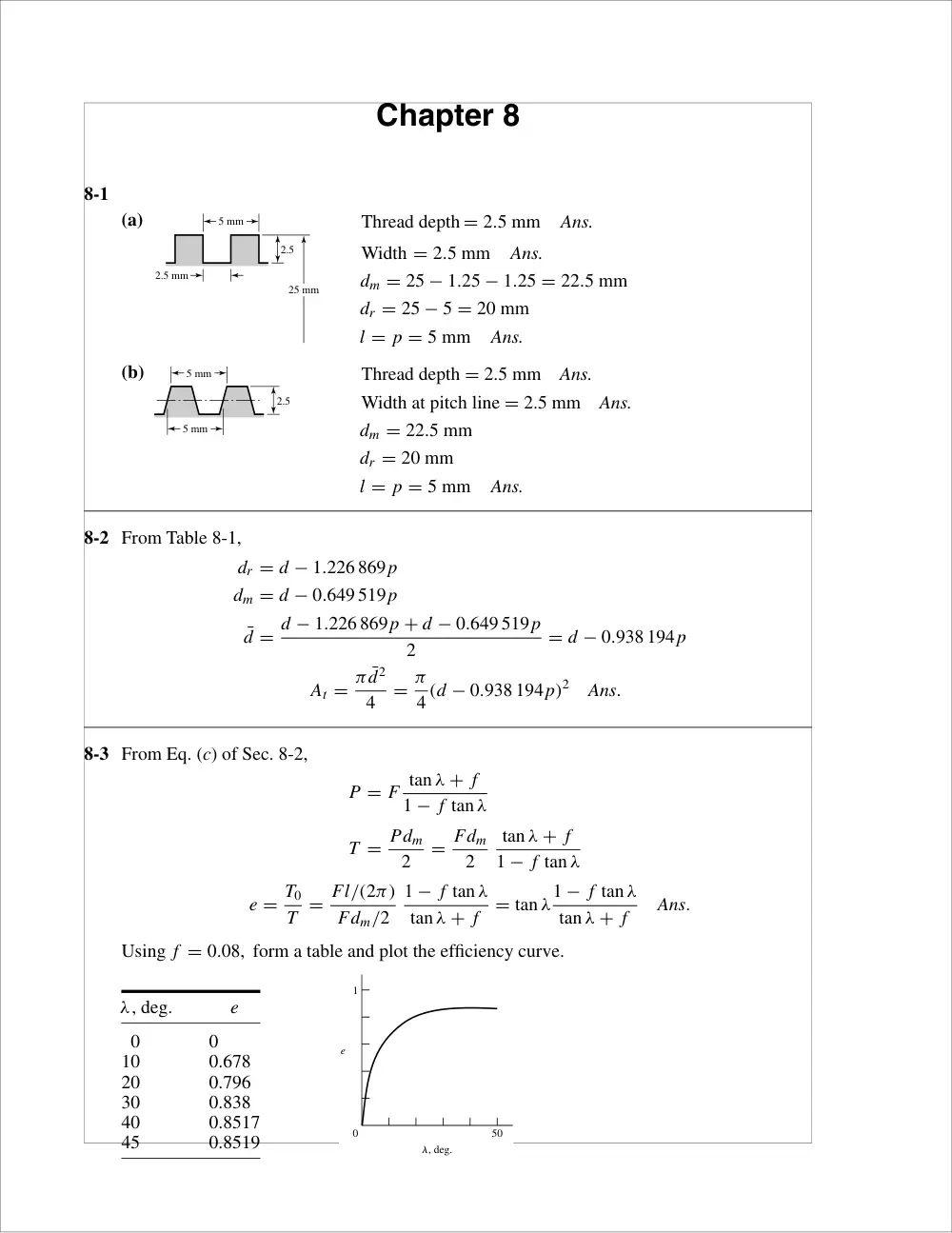
8-1
(a)
Thread depth = 2.5 mm
Ans.
Width = 2.5 mm
Ans.
dm = 25 − 1.25 − 1.25 = 22.5 mm
dr = 25 − 5 = 20 mm
l = p = 5 mm
Ans.
(b)
Thread depth = 2.5 mm
Ans.
Width at pitch line = 2.5 mm
Ans.
dm = 22.5 mm
dr = 20 mm
l = p = 5 mm
Ans.
8-2 From Table 8-1,
dr = d − 1.226 869p
dm = d − 0.649 519p
¯d = d − 1.226 869p + d − 0.649 519p
2
= d − 0.938 194p
At = π ¯d2
4
= π
4 (d − 0.938 194p)2
Ans.
8-3 From Eq. (c) of Sec. 8-2,
P = F tan λ + f
1 − f tan λ
T = Pdm
2
= Fdm
2
tan λ + f
1 − f tan λ
e = T0
T = Fl/(2π)
Fdm/2
1 − f tan λ
tan λ + f
= tan λ1 − f tan λ
tan λ + f
Ans.
Using f = 0.08, form a table and plot the efficiency curve.
λ, deg.
e
0
0
10
0.678
20
0.796
30
0.838
40
0.8517
45
0.8519
1
0
50
�, deg.
e
5 mm
5 mm
2.5
2.5
2.5 mm
25 mm
5 mm
Chapter 8
205
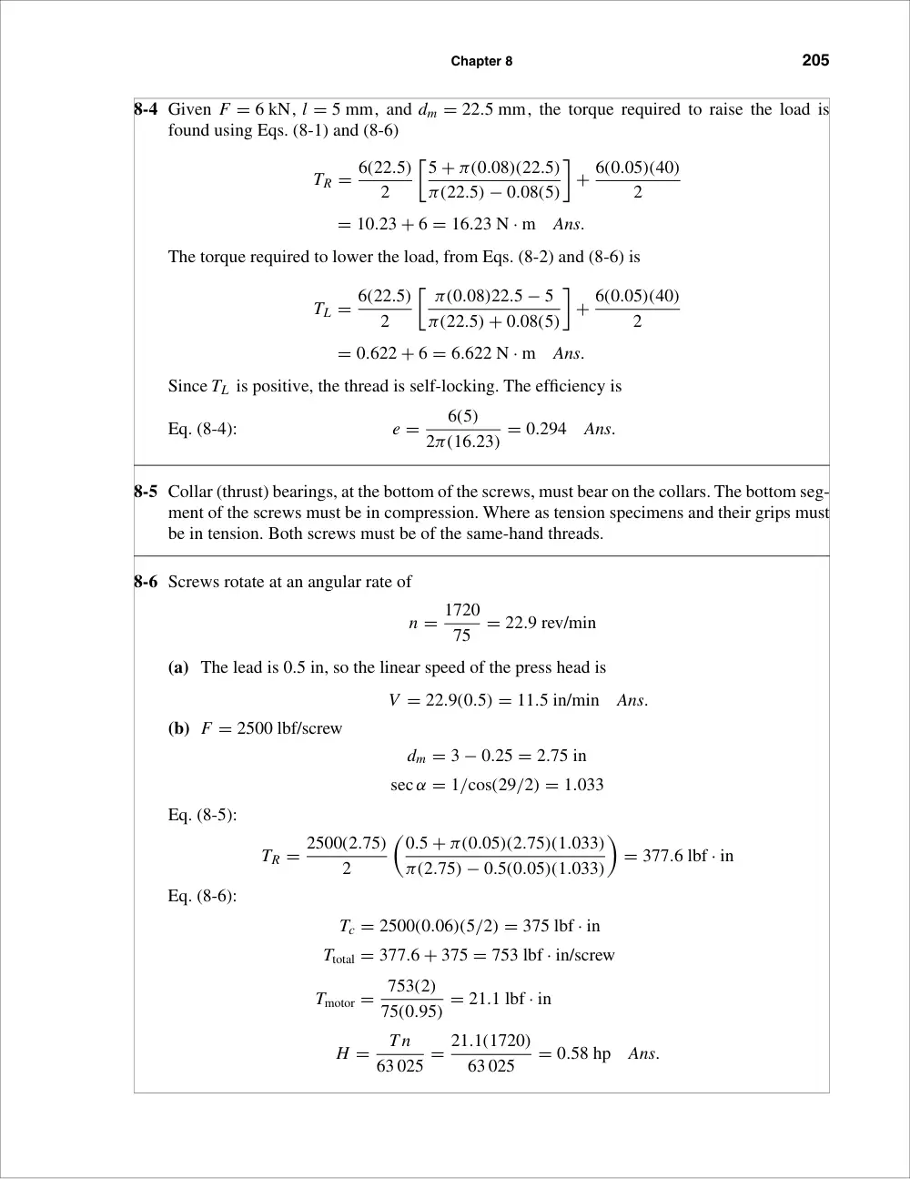
8-4 Given F = 6 kN, l = 5 mm, and dm = 22.5 mm, the torque required to raise the load is
found using Eqs. (8-1) and (8-6)
TR = 6(22.5)
2
�5 + π(0.08)(22.5)
π(22.5) − 0.08(5)
�
+ 6(0.05)(40)
2
= 10.23 + 6 = 16.23 N · m
Ans.
The torque required to lower the load, from Eqs. (8-2) and (8-6) is
TL = 6(22.5)
2
� π(0.08)22.5 − 5
π(22.5) + 0.08(5)
�
+ 6(0.05)(40)
2
= 0.622 + 6 = 6.622 N · m
Ans.
Since TL is positive, the thread is self-locking. The efficiency is
Eq. (8-4):
e =
6(5)
2π(16.23) = 0.294
Ans.
8-5 Collar (thrust) bearings, at the bottom of the screws, must bear on the collars. The bottom seg-
ment of the screws must be in compression. Where as tension specimens and their grips must
be in tension. Both screws must be of the same-hand threads.
8-6 Screws rotate at an angular rate of
n = 1720
75
= 22.9 rev/min
(a) The lead is 0.5 in, so the linear speed of the press head is
V = 22.9(0.5) = 11.5 in/min
Ans.
(b) F = 2500 lbf/screw
dm = 3 − 0.25 = 2.75 in
sec α = 1/cos(29/2) = 1.033
Eq. (8-5):
TR = 2500(2.75)
2
�0.5 + π(0.05)(2.75)(1.033)
π(2.75) − 0.5(0.05)(1.033)
�
= 377.6 lbf · in
Eq. (8-6):
Tc = 2500(0.06)(5/2) = 375 lbf · in
Ttotal = 377.6 + 375 = 753 lbf · in/screw
Tmotor = 753(2)
75(0.95) = 21.1 lbf · in
H =
Tn
63 025 = 21.1(1720)
63 025
= 0.58 hp
Ans.
206
Solutions Manual • Instructor’s Solution Manual to Accompany Mechanical Engineering Design
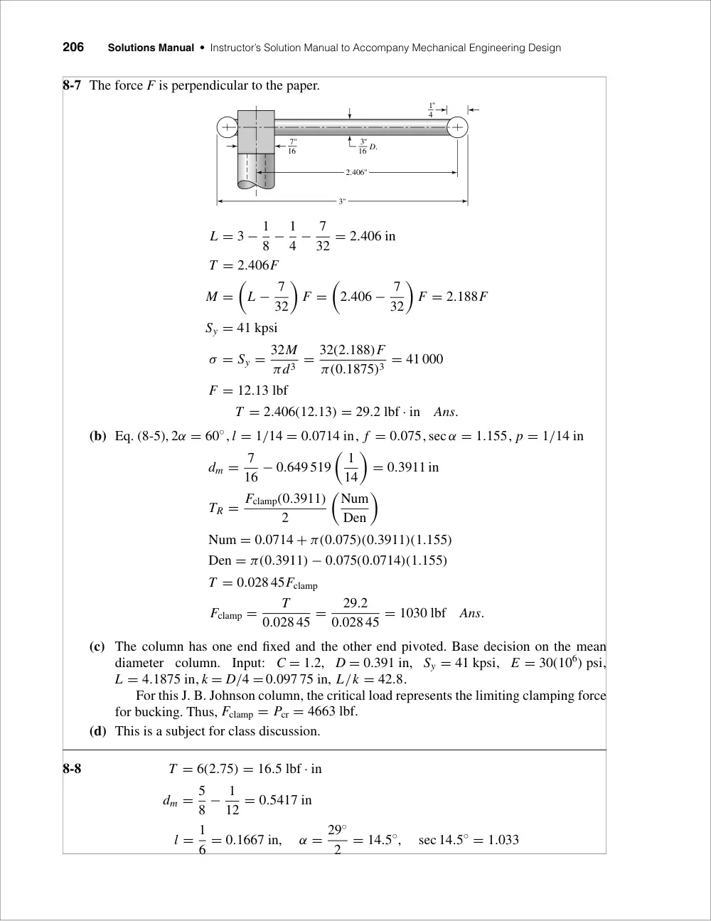
8-7 The force F is perpendicular to the paper.
L = 3 − 1
8 − 1
4 − 7
32 = 2.406 in
T = 2.406F
M =
�
L − 7
32
�
F =
�
2.406 − 7
32
�
F = 2.188F
Sy = 41 kpsi
σ = Sy = 32M
πd3 = 32(2.188)F
π(0.1875)3 = 41 000
F = 12.13 lbf
T = 2.406(12.13) = 29.2 lbf · in
Ans.
(b) Eq. (8-5), 2α = 60◦, l = 1/14 = 0.0714 in, f = 0.075, sec α = 1.155, p = 1/14 in
dm = 7
16 − 0.649 519
� 1
14
�
= 0.3911 in
TR = Fclamp(0.3911)
2
�Num
Den
�
Num = 0.0714 + π(0.075)(0.3911)(1.155)
Den = π(0.3911) − 0.075(0.0714)(1.155)
T = 0.028 45Fclamp
Fclamp =
T
0.028 45 =
29.2
0.028 45 = 1030 lbf
Ans.
(c) The column has one end fixed and the other end pivoted. Base decision on the mean
diameter
column.
Input: C = 1.2, D = 0.391 in, Sy = 41 kpsi,
E = 30(106) psi,
L = 4.1875 in, k = D/4 = 0.097 75 in, L/k = 42.8.
For this J. B. Johnson column, the critical load represents the limiting clamping force
for bucking. Thus, Fclamp = Pcr = 4663 lbf.
(d) This is a subject for class discussion.
8-8
T = 6(2.75) = 16.5 lbf · in
dm = 5
8 − 1
12 = 0.5417 in
l = 1
6 = 0.1667 in,
α = 29◦
2
= 14.5◦,
sec 14.5◦ = 1.033
1
4
"
3
16 D.
"
7
16
"
2.406"
3"
Chapter 8
207
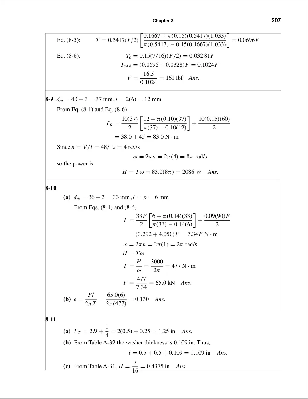
Eq. (8-5):
T = 0.5417(F/2)
�0.1667 + π(0.15)(0.5417)(1.033)
π(0.5417) − 0.15(0.1667)(1.033)
�
= 0.0696F
Eq. (8-6):
Tc = 0.15(7/16)(F/2) = 0.032 81F
Ttotal = (0.0696 + 0.0328)F = 0.1024F
F =
16.5
0.1024 = 161 lbf
Ans.
8-9 dm = 40 − 3 = 37 mm, l = 2(6) = 12 mm
From Eq. (8-1) and Eq. (8-6)
TR = 10(37)
2
�12 + π(0.10)(37)
π(37) − 0.10(12)
�
+ 10(0.15)(60)
2
= 38.0 + 45 = 83.0 N · m
Since n = V/l = 48/12 = 4 rev/s
ω = 2πn = 2π(4) = 8π rad/s
so the power is
H = Tω = 83.0(8π) = 2086 W
Ans.
8-10
(a) dm = 36 − 3 = 33 mm, l = p = 6 mm
From Eqs. (8-1) and (8-6)
T = 33F
2
�6 + π(0.14)(33)
π(33) − 0.14(6)
�
+ 0.09(90)F
2
= (3.292 + 4.050)F = 7.34F N · m
ω = 2πn = 2π(1) = 2π rad/s
H = Tω
T = H
ω = 3000
2π
= 477 N · m
F = 477
7.34 = 65.0 kN
Ans.
(b) e =
Fl
2πT = 65.0(6)
2π(477) = 0.130
Ans.
8-11
(a) LT = 2D + 1
4 = 2(0.5) + 0.25 = 1.25 in
Ans.
(b) From Table A-32 the washer thickness is 0.109 in. Thus,
l = 0.5 + 0.5 + 0.109 = 1.109 in
Ans.
(c) From Table A-31, H = 7
16 = 0.4375 in
Ans.
208
Solutions Manual • Instructor’s Solution Manual to Accompany Mechanical Engineering Design
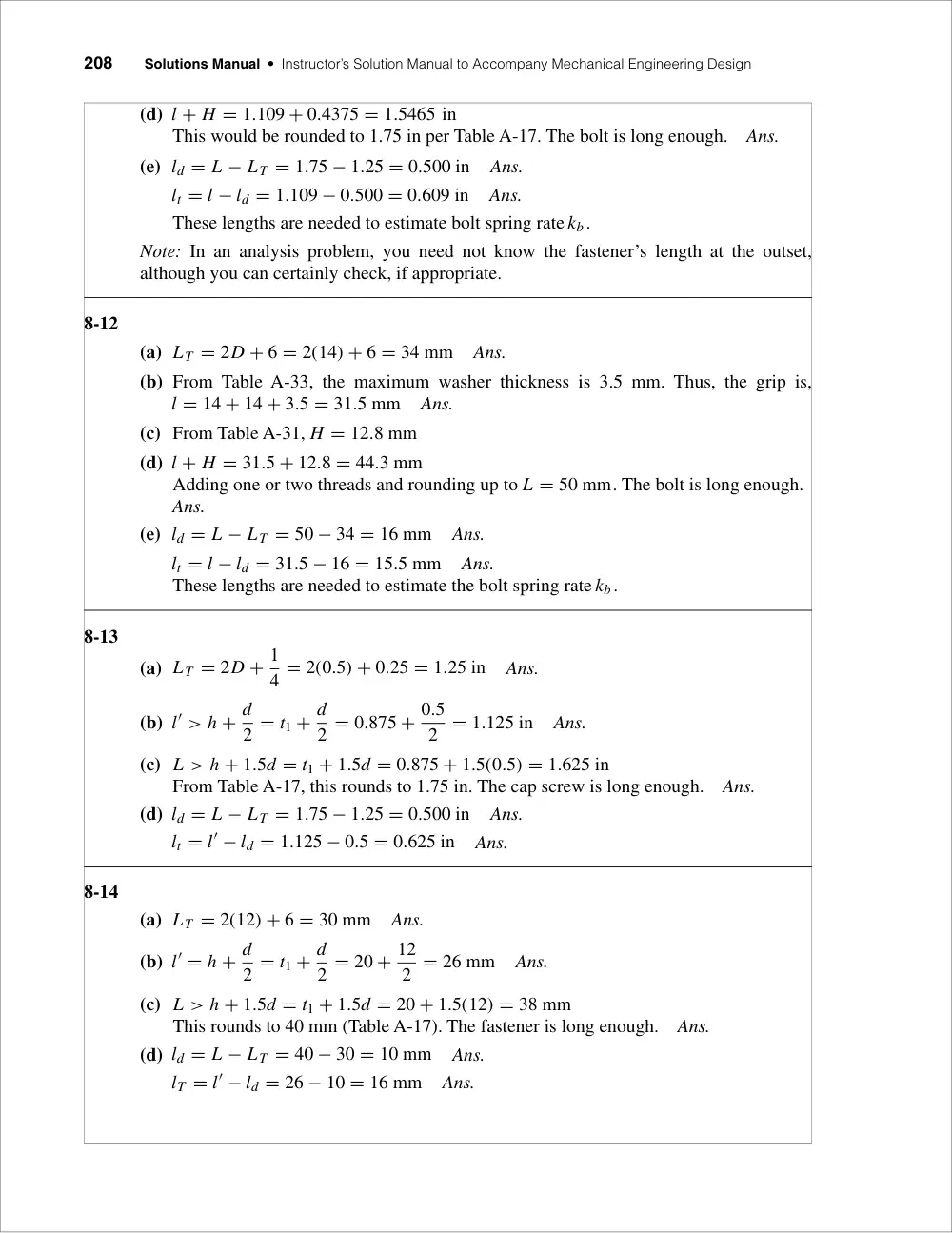
(d) l + H = 1.109 + 0.4375 = 1.5465 in
This would be rounded to 1.75 in per Table A-17. The bolt is long enough.
Ans.
(e) ld = L − LT = 1.75 − 1.25 = 0.500 in
Ans.
lt = l − ld = 1.109 − 0.500 = 0.609 in
Ans.
These lengths are needed to estimate bolt spring rate kb.
Note: In an analysis problem, you need not know the fastener’s length at the outset,
although you can certainly check, if appropriate.
8-12
(a) LT = 2D + 6 = 2(14) + 6 = 34 mm
Ans.
(b) From Table A-33, the maximum washer thickness is 3.5 mm. Thus, the grip is,
l = 14 + 14 + 3.5 = 31.5 mm
Ans.
(c) From Table A-31, H = 12.8 mm
(d) l + H = 31.5 + 12.8 = 44.3 mm
Adding one or two threads and rounding up to L = 50 mm. The bolt is long enough.
Ans.
(e) ld = L − LT = 50 − 34 = 16 mm
Ans.
lt = l − ld = 31.5 − 16 = 15.5 mm
Ans.
These lengths are needed to estimate the bolt spring rate kb.
8-13
(a) LT = 2D + 1
4 = 2(0.5) + 0.25 = 1.25 in
Ans.
(b) l′ > h + d
2 = t1 + d
2 = 0.875 + 0.5
2 = 1.125 in
Ans.
(c) L > h + 1.5d = t1 + 1.5d = 0.875 + 1.5(0.5) = 1.625 in
From Table A-17, this rounds to 1.75 in. The cap screw is long enough.
Ans.
(d) ld = L − LT = 1.75 − 1.25 = 0.500 in
Ans.
lt = l′ − ld = 1.125 − 0.5 = 0.625 in
Ans.
8-14
(a) LT = 2(12) + 6 = 30 mm
Ans.
(b) l′ = h + d
2 = t1 + d
2 = 20 + 12
2 = 26 mm
Ans.
(c) L > h + 1.5d = t1 + 1.5d = 20 + 1.5(12) = 38 mm
This rounds to 40 mm (Table A-17). The fastener is long enough.
Ans.
(d) ld = L − LT = 40 − 30 = 10 mm
Ans.
lT = l′ − ld = 26 − 10 = 16 mm
Ans.
Chapter 8
209
8-15
(a)
Ad = 0.7854(0.75)2 = 0.442 in2
Atube = 0.7854(1.1252 − 0.752) = 0.552 in2
kb = Ad E
grip = 0.442(30)(106)
13
= 1.02(106) lbf/in
Ans.
km = AtubeE
13
= 0.552(30)(106)
13
= 1.27(106) lbf/in
Ans.
C =
1.02
1.02 + 1.27 = 0.445
Ans.
(b)
δ = 1
16 · 1
3 = 1
48 = 0.020 83 in
|δb| =
�|P|l
AE
�
b
= (13 − 0.020 83)
0.442(30)(106) |P| = 9.79(10−7)|P| in
|δm| =
�|P|l
AE
�
m
=
|P|(13)
0.552(30)(106) = 7.85(10−7)|P| in
|δb| + |δm| = δ = 0.020 83
9.79(10−7)|P| + 7.85(10−7)|P| = 0.020 83
Fi = |P| =
0.020 83
9.79(10−7) + 7.85(10−7) = 11 810 lbf
Ans.
(c) At opening load P0
9.79(10−7)P0 = 0.020 83
P0 =
0.020 83
9.79(10−7) = 21 280 lbf
Ans.
As a check use Fi = (1 − C)P0
P0 =
Fi
1 − C =
11 810
1 − 0.445 = 21 280 lbf
8-16
The movement is known at one location when the nut is free to turn
δ = pt = t/N
Letting Nt represent the turn of the nut from snug tight, Nt = θ/360◦ and δ = Nt/N.
The elongation of the bolt δb is
δb = Fi
kb
The advance of the nut along the bolt is the algebraic sum of |δb| and |δm|
Original bolt
Nut advance
A
A
�
�m
�b
Equilibrium
Grip
210
Solutions Manual • Instructor’s Solution Manual to Accompany Mechanical Engineering Design
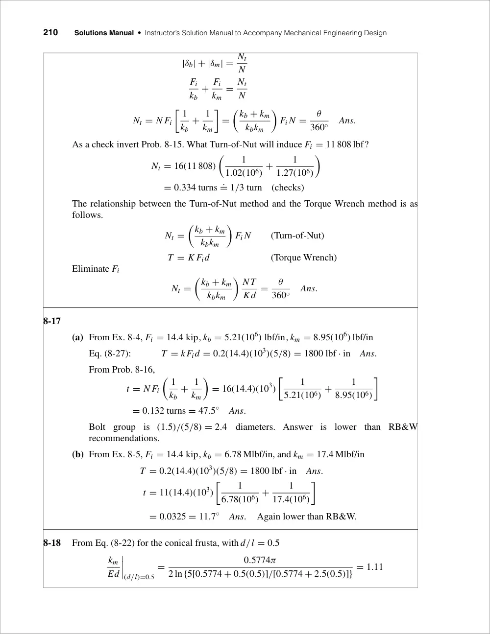
|δb| + |δm| = Nt
N
Fi
kb
+ Fi
km
= Nt
N
Nt = N Fi
� 1
kb
+ 1
km
�
=
�kb + km
kbkm
�
Fi N =
θ
360◦
Ans.
As a check invert Prob. 8-15. What Turn-of-Nut will induce Fi = 11 808 lbf?
Nt = 16(11 808)
�
1
1.02(106) +
1
1.27(106)
�
= 0.334 turns .= 1/3 turn
(checks)
The relationship between the Turn-of-Nut method and the Torque Wrench method is as
follows.
Nt =
�kb + km
kbkm
�
Fi N
(Turn-of-Nut)
T = K Fid
(Torque Wrench)
Eliminate Fi
Nt =
�kb + km
kbkm
� NT
Kd =
θ
360◦
Ans.
8-17
(a) From Ex. 8-4, Fi = 14.4 kip, kb = 5.21(106) lbf/in, km = 8.95(106) lbf/in
Eq. (8-27):
T = kFid = 0.2(14.4)(103)(5/8) = 1800 lbf · in
Ans.
From Prob. 8-16,
t = N Fi
� 1
kb
+ 1
km
�
= 16(14.4)(103)
�
1
5.21(106) +
1
8.95(106)
�
= 0.132 turns = 47.5◦
Ans.
Bolt group is (1.5)/(5/8) = 2.4
diameters. Answer is lower than RB&W
recommendations.
(b) From Ex. 8-5, Fi = 14.4 kip, kb = 6.78 Mlbf/in, and km = 17.4 Mlbf/in
T = 0.2(14.4)(103)(5/8) = 1800 lbf · in
Ans.
t = 11(14.4)(103)
�
1
6.78(106) +
1
17.4(106)
�
= 0.0325 = 11.7◦
Ans.
Again lower than RB&W.
8-18
From Eq. (8-22) for the conical frusta, with d/l = 0.5
km
Ed
����
(d/l)=0.5
=
0.5774π
2 ln {5[0.5774 + 0.5(0.5)]/[0.5774 + 2.5(0.5)]} = 1.11
Chapter 8
211
Eq. (8-23), from the Wileman et al. finite element study, using the general expression,
km
Ed
����
(d/l)=0.5
= 0.789 52 exp[0.629 14(0.5)] = 1.08
8-19
For cast iron, from Table 8-8: A = 0.778 71, B = 0.616 16, E = 14.5 Mpsi
km = 14.5(106)(0.625)(0.778 71) exp
�
0.616 160.625
1.5
�
= 9.12(106) lbf/in
This member’s spring rate applies to both members. We need km for the upper member
which represents half of the joint.
kci = 2km = 2[9.12(106)] = 18.24(106) lbf/in
For steel from Table 8-8: A = 0.787 15, B = 0.628 73, E = 30 Mpsi
km = 30(106)(0.625)(0.787 15) exp
�
0.628 730.625
1.5
�
= 19.18(106) lbf/in
ksteel = 2km = 2(19.18)(106) = 38.36(106) lbf/in
For springs in series
1
km
= 1
kci
+
1
ksteel
=
1
18.24(106) +
1
38.36(106)
km = 12.4(106) lbf/in
Ans.
8-20
The external tensile load per bolt is
P = 1
10
�π
4
�
(150)2(6)(10−3) = 10.6 kN
Also, l = 40 mm and from Table A-31, for d = 12 mm, H = 10.8 mm. No washer is
specified.
LT = 2D + 6 = 2(12) + 6 = 30 mm
l + H = 40 + 10.8 = 50.8 mm
Table A-17:
L = 60 mm
ld = 60 − 30 = 30 mm
lt = 45 − 30 = 15 mm
Ad = π(12)2
4
= 113 mm2
Table 8-1:
At = 84.3 mm2
Eq. (8-17):
kb =
113(84.3)(207)
113(15) + 84.3(30) = 466.8 MN/m
Steel: Using Eq. (8-23) for A = 0.787 15, B = 0.628 73 and E = 207 GPa
212
Solutions Manual • Instructor’s Solution Manual to Accompany Mechanical Engineering Design
Eq. (8-23):
km = 207(12)(0.787 15) exp[(0.628 73)(12/40)] = 2361 MN/m
ks = 2km = 4722 MN/m
Cast iron: A = 0.778 71, B = 0.616 16, E = 100 GPa
km = 100(12)(0.778 71) exp[(0.616 16)(12/40)] = 1124 MN/m
kci = 2km = 2248 MN/m
1
km
= 1
ks
+ 1
kci
⇒
km = 1523 MN/m
C =
466.8
466.8 + 1523 = 0.2346
Table 8-1: At = 84.3 mm2, Table 8-11, Sp = 600 MPa
Eqs. (8-30) and (8-31):
Fi = 0.75(84.3)(600)(10−3) = 37.9 kN
Eq. (8-28):
n = Sp At − Fi
C P
= 600(10−3)(84.3) − 37.9
0.2346(10.6)
= 5.1
Ans.
8-21
Computer programs will vary.
8-22
D3 = 150 mm, A = 100 mm, B = 200 mm, C = 300 mm, D = 20 mm, E = 25 mm.
ISO 8.8 bolts: d = 12 mm, p = 1.75 mm, coarse pitch of p = 6 MPa.
P = 1
10
�π
4
�
(1502)(6)(10−3) = 10.6 kN/bolt
l = D + E = 20 + 25 = 45 mm
LT = 2D + 6 = 2(12) + 6 = 30 mm
Table A-31: H = 10.8 mm
l + H = 45 + 10.8 = 55.8 mm
Table A-17: L = 60 mm
ld = 60 − 30 = 30 mm,
lt = 45 − 30 = 15 mm,
Ad = π(122/4) = 113 mm2
Table 8-1: At = 84.3 mm2
2.5
dw
D1
22.5 25
45
20
Chapter 8
213
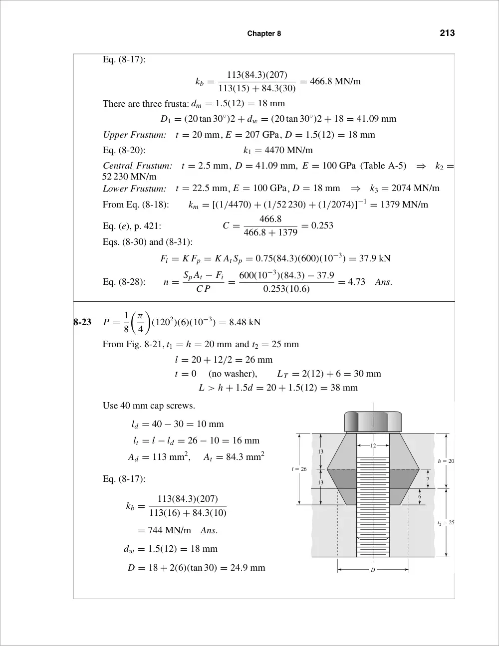
Eq. (8-17):
kb =
113(84.3)(207)
113(15) + 84.3(30) = 466.8 MN/m
There are three frusta: dm = 1.5(12) = 18 mm
D1 = (20 tan 30◦)2 + dw = (20 tan 30◦)2 + 18 = 41.09 mm
Upper Frustum:
t = 20 mm, E = 207 GPa, D = 1.5(12) = 18 mm
Eq. (8-20):
k1 = 4470 MN/m
Central Frustum:
t = 2.5 mm, D = 41.09 mm, E = 100 GPa (Table A-5)
⇒
k2 =
52 230 MN/m
Lower Frustum:
t = 22.5 mm, E = 100 GPa, D = 18 mm
⇒
k3 = 2074 MN/m
From Eq. (8-18):
km = [(1/4470) + (1/52 230) + (1/2074)]−1 = 1379 MN/m
Eq. (e), p. 421:
C =
466.8
466.8 + 1379 = 0.253
Eqs. (8-30) and (8-31):
Fi = K Fp = K At Sp = 0.75(84.3)(600)(10−3) = 37.9 kN
Eq. (8-28):
n = Sp At − Fi
C P
= 600(10−3)(84.3) − 37.9
0.253(10.6)
= 4.73
Ans.
8-23
P = 1
8
�π
4
�
(1202)(6)(10−3) = 8.48 kN
From Fig. 8-21, t1 = h = 20 mm and t2 = 25 mm
l = 20 + 12/2 = 26 mm
t = 0
(no washer),
LT = 2(12) + 6 = 30 mm
L > h + 1.5d = 20 + 1.5(12) = 38 mm
Use 40 mm cap screws.
ld = 40 − 30 = 10 mm
lt = l − ld = 26 − 10 = 16 mm
Ad = 113 mm2,
At = 84.3 mm2
Eq. (8-17):
kb =
113(84.3)(207)
113(16) + 84.3(10)
= 744 MN/m
Ans.
dw = 1.5(12) = 18 mm
D = 18 + 2(6)(tan 30) = 24.9 mm
l � 26
t2 � 25
h � 20
13
13
7
6
D
12
214
Solutions Manual • Instructor’s Solution Manual to Accompany Mechanical Engineering Design
From Eq. (8-20):
Top frustum:
D = 18, t = 13, E = 207 GPa
⇒
k1 = 5316 MN/m
Mid-frustum:
t = 7, E = 207 GPa, D = 24.9 mm
⇒
k2 = 15 620 MN/m
Bottom frustum:
D = 18, t = 6, E = 100 GPa
⇒
k3 = 3887 MN/m
km =
1
(1/5316) + (1/55 620) + (1/3887) = 2158 MN/m
Ans.
C =
744
744 + 2158 = 0.256
Ans.
From Prob. 8-22, Fi = 37.9 kN
n = Sp At − Fi
C P
= 600(0.0843) − 37.9
0.256(8.48)
= 5.84
Ans.
8-24
Calculation of bolt stiffness:
H = 7/16 in
LT = 2(1/2) + 1/4 = 1 1/4 in
l = 1/2 + 5/8 + 0.095 = 1.22 in
L > 1.125 + 7/16 + 0.095 = 1.66 in
Use L = 1.75 in
ld = L − LT = 1.75 − 1.25 = 0.500 in
lt = 1.125 + 0.095 − 0.500 = 0.72 in
Ad = π(0.502)/4 = 0.1963 in2
At = 0.1419 in2 (UNC)
kt = At E
lt
= 0.1419(30)
0.72
= 5.9125 Mlbf/in
kd = Ad E
ld
= 0.1963(30)
0.500
= 11.778 Mlbf/in
kb =
1
(1/5.9125) + (1/11.778) = 3.936 Mlbf/in
Ans.
5
8
1
2
0.095
3
4
1.454
1.327
3
4
0.860
1.22
0.61
Chapter 8
215
Member stiffness for four frusta and joint constant C using Eqs. (8-20) and (e).
Top frustum:
D = 0.75, t = 0.5, d = 0.5, E = 30
⇒
k1 = 33.30 Mlbf/in
2nd frustum:
D = 1.327, t = 0.11, d = 0.5, E = 14.5
⇒
k2 = 173.8 Mlbf/in
3rd frustum:
D = 0.860, t = 0.515, E = 14.5
⇒
k3 = 21.47 Mlbf/in
Fourth frustum:
D = 0.75, t = 0.095, d = 0.5, E = 30
⇒
k4 = 97.27 Mlbf/in
km =
� 4
�
i=1
1/ki
�−1
= 10.79 Mlbf/in
Ans.
C = 3.94/(3.94 + 10.79) = 0.267
Ans.
8-25
kb = At E
l
= 0.1419(30)
0.845
= 5.04 Mlbf/in
Ans.
From Fig. 8-21,
h = 1
2 + 0.095 = 0.595 in
l = h + d
2 = 0.595 + 0.5
2 = 0.845
D1 = 0.75 + 0.845 tan 30◦ = 1.238 in
l/2 = 0.845/2 = 0.4225 in
From Eq. (8-20):
Frustum 1:
D = 0.75, t = 0.4225 in, d = 0.5 in, E = 30 Mpsi ⇒ k1 = 36.14 Mlbf/in
Frustum 2:
D = 1.018 in, t = 0.1725 in, E = 70 Mpsi, d = 0.5 in ⇒ k2 = 134.6 Mlbf/in
Frustum 3:
D = 0.75, t = 0.25 in, d = 0.5 in, E = 14.5 Mpsi ⇒ k3 = 23.49 Mlbf/in
km =
1
(1/36.14) + (1/134.6) + (1/23.49) = 12.87 Mlbf/in
Ans.
C =
5.04
5.04 + 12.87 = 0.281
Ans.
0.095"
0.1725"
0.25"
0.595"
0.5"
0.625"
0.4225"
0.845"
0.75"
1.018"
1.238"
Steel
Cast
iron
216
Solutions Manual • Instructor’s Solution Manual to Accompany Mechanical Engineering Design
8-26
Refer to Prob. 8-24 and its solution.Additional information: A = 3.5 in, Ds = 4.25 in, static
pressure 1500 psi, Db = 6 in,C (joint constant) = 0.267, ten SAE grade 5 bolts.
P = 1
10
π(4.252)
4
(1500) = 2128 lbf
From Tables 8-2 and 8-9,
At = 0.1419 in2
Sp = 85 000 psi
Fi = 0.75(0.1419)(85) = 9.046 kip
From Eq. (8-28),
n = Sp At − Fi
C P
= 85(0.1419) − 9.046
0.267(2.128)
= 5.31
Ans.
8-27
From Fig. 8-21, t1 = 0.25 in
h = 0.25 + 0.065 = 0.315 in
l = h + (d/2) = 0.315 + (3/16) = 0.5025 in
D1 = 1.5(0.375) + 0.577(0.5025) = 0.8524 in
D2 = 1.5(0.375) = 0.5625 in
l/2 = 0.5025/2 = 0.251 25 in
Frustum 1: Washer
E = 30 Mpsi,
t = 0.065 in,
D = 0.5625 in
k = 78.57 Mlbf/in
(by computer)
Frustum 2: Cap portion
E = 14 Mpsi,
t = 0.186 25 in
D = 0.5625 + 2(0.065)(0.577) = 0.6375 in
k = 23.46 Mlbf/in
(by computer)
Frustum 3: Frame and Cap
E = 14 Mpsi,
t = 0.251 25 in,
D = 0.5625 in
k = 14.31 Mlbf/in
(by computer)
km =
1
(1/78.57) + (1/23.46) + (1/14.31) = 7.99 Mlbf/in
Ans.
0.8524"
0.5625"
0.25125"
0.8524"
0.6375"
0.18625"
0.5625"
0.6375"
0.065"
Chapter 8
217
For the bolt, LT = 2(3/8) + (1/4) = 1 in. So the bolt is threaded all the way. Since
At = 0.0775 in2
kb = 0.0775(30)
0.5025
= 4.63 Mlbf/in
Ans.
8-28
(a) F′
b = RF′
b,max sin θ
Half of the external moment is contributed by the line load in the interval 0 ≤ θ ≤ π.
M
2 =
� π
0
F′
bR2 sin θ dθ =
� π
0
F′
b, maxR2 sin2 θ dθ
M
2 = π
2 F′
b, maxR2
from which F′
b,max =
M
π R2
Fmax =
� φ2
φ1
F′
bR sin θ dθ =
M
π R2
� φ2
φ1
R sin θ dθ = M
π R(cos φ1 − cos φ2)
Noting φ1 = 75◦, φ2 = 105◦
Fmax = 12 000
π(8/2)(cos 75◦ − cos 105◦) = 494 lbf
Ans.
(b)
Fmax = F′
b, maxR�φ =
M
π R2(R)
�2π
N
�
= 2M
RN
Fmax = 2(12 000)
(8/2)(12) = 500 lbf
Ans.
(c) F = Fmax sin θ
M = 2FmaxR[(1) sin2 90◦ + 2 sin2 60◦ + 2 sin2 30◦ + (1) sin2(0)] = 6FmaxR
from which
Fmax = M
6R = 12 000
6(8/2) = 500 lbf
Ans.
The simple general equation resulted from part (b)
Fmax = 2M
RN
8-29
(a) Table 8-11:
Sp = 600 MPa
Eq. (8-30):
Fi = 0.9At Sp = 0.9(245)(600)(10−3) = 132.3 kN
Table (8-15):
K = 0.18
Eq. (8-27)
T = 0.18(132.3)(20) = 476 N · m
Ans.
218
Solutions Manual • Instructor’s Solution Manual to Accompany Mechanical Engineering Design
(b) Washers:t = 3.4 mm, d = 20 mm, D = 30 mm, E = 207 GPa ⇒ k1 = 42 175 MN/m
Cast iron: t = 20 mm, d = 20 mm, D = 30 + 2(3.4) tan 30◦ = 33.93 mm,
E = 135 GPa
⇒
k2 = 7885 MN/m
Steel: t = 20 mm, d = 20 mm, D = 33.93 mm, E = 207 GPa ⇒ k3 = 12 090 MN/m
km = (2/42 175 + 1/7885 + 1/12 090)−1 = 3892 MN/m
Bolt: l = 46.8 mm. Nut: H = 18 mm. L > 46.8 + 18 = 64.8 mm. Use L = 80 mm.
LT = 2(20) + 6 = 46 mm, ld = 80 − 46 = 34 mm, lt = 46.8 − 34 = 12.8 mm,
At = 245 mm2,
Ad = π202/4 = 314.2 mm2
kb =
Ad At E
Adlt + Atld
=
314.2(245)(207)
314.2(12.8) + 245(34) = 1290 MN/m
C = 1290/(1290 + 3892) = 0.2489,
Sp = 600 MPa,
Fi = 132.3 kN
n = Sp At − Fi
C(P/N) = 600(0.245) − 132.3
0.2489(15/4)
= 15.7
Ans.
Bolts are a bit oversized for the load.
8-30
(a) ISO M 20 × 2.5 grade 8.8 coarse pitch bolts, lubricated.
Table 8-2
At = 245 mm2
Table 8-11
Sp = 600 MPa
Ad = π(20)2/4 = 314.2 mm2
Fp = 245(0.600) = 147 kN
Fi = 0.90Fp = 0.90(147) = 132.3 kN
T = 0.18(132.3)(20) = 476 N · m
Ans.
(b) L ≥ l + H = 48 + 18 = 66 mm. Therefore, set L = 80 mm per Table A-17.
LT = 2D + 6 = 2(20) + 6 = 46 mm
ld = L − LT = 80 − 46 = 34 mm
lt = l − ld = 48 − 34 = 14 mm
14
Not to
scale
80
48 grip
46
34
Chapter 8
219
kb =
Ad At E
Adlt + Atld
=
314.2(245)(207)
314.2(14) + 245(34) = 1251.9 MN/m
Use Wileman et al.
Eq. (8-23)
A = 0.787 15,
B = 0.628 73
km
Ed = A exp
� Bd
LG
�
= 0.787 15 exp
�
0.628 73
�20
48
��
= 1.0229
km = 1.0229(207)(20) = 4235 MN/m
C =
1251.9
1251.9 + 4235 = 0.228
Bolts carry 0.228 of the external load; members carry 0.772 of the external load.
Ans.
Thus, the actual loads are
Fb = C P + Fi = 0.228(20) + 132.3 = 136.9 kN
Fm = (1 − C)P − Fi = (1 − 0.228)20 − 132.3 = −116.9 kN
8-31
Given pmax = 6 MPa, pmin = 0 and from Prob. 8-20 solution, C = 0.2346, Fi = 37.9 kN,
At = 84.3 mm2.
For 6 MPa, P = 10.6 kN per bolt
σi = Fi
At
= 37.9(103)
84.3
= 450 MPa
Eq. (8-35):
σa = C P
2At
= 0.2346(10.6)(103)
2(84.3)
= 14.75 MPa
σm = σa + σi = 14.75 + 450 = 464.8 MPa
(a) Goodman Eq. (8-40) for 8.8 bolts with Se = 129 MPa, Sut = 830 MPa
Sa = Se(Sut − σi)
Sut + Se
= 129(830 − 450)
830 + 129
= 51.12 MPa
n f = Sa
σa
= 51.12
14.75 = 3.47
Ans.
24
24
30
30
220
Solutions Manual • Instructor’s Solution Manual to Accompany Mechanical Engineering Design
(b) Gerber Eq. (8-42)
Sa =
1
2Se
�
Sut
�
S2ut + 4Se(Se + σi) − S2
ut − 2σi Se
�
=
1
2(129)
�
830
�
8302 + 4(129)(129 + 450) − 8302 − 2(450)(129)
�
= 76.99 MPa
n f = 76.99
14.75 = 5.22
Ans.
(c) ASME-elliptic Eq. (8-43) with Sp = 600 MPa
Sa =
Se
S2p + S2e
�
Sp
�
S2p + S2e − σ 2
i − σi Se
�
=
129
6002 + 1292
�
600
�
6002 + 1292 − 4502 − 450(129)
�
= 65.87 MPa
n f = 65.87
14.75 = 4.47
Ans.
8-32
P = pA
N = π D2 p
4N
= π(0.92)(550)
4(36)
= 9.72 kN/bolt
Table 8-11:
Sp = 830 MPa,
Sut = 1040 MPa,
Sy = 940 MPa
Table 8-1:
At = 58 mm2
Ad = π(102)/4 = 78.5 mm2
l = D + E = 20 + 25 = 45 mm
LT = 2(10) + 6 = 26 mm
Table A-31:
H = 8.4 mm
L ≥ l + H = 45 + 8.4 = 53.4 mm
Choose L = 60 mm from Table A-17
ld = L − LT = 60 − 26 = 34 mm
lt = l − ld = 45 − 34 = 11 mm
kb =
Ad At E
Adlt + Atld
=
78.5(58)(207)
78.5(11) + 58(34) = 332.4 MN/m
2.5
22.5
22.5
25
20
15
10
Chapter 8
221
Frustum 1:
Top, E = 207, t = 20 mm, d = 10 mm, D = 15 mm
k1 =
0.5774π(207)(10)
ln
��1.155(20) + 15 − 10
1.155(20) + 15 + 10
� �15 + 10
15 − 10
��
= 3503 MN/m
Frustum 2:
Middle, E = 96 GPa, D = 38.09 mm, t = 2.5 mm, d = 10 mm
k2 =
0.5774π(96)(10)
ln
��1.155(2.5) + 38.09 − 10
1.155(2.5) + 38.09 + 10
� �38.09 + 10
38.09 − 10
��
= 44 044 MN/m
could be neglected due to its small influence on km.
Frustum 3:
Bottom, E = 96 GPa, t = 22.5 mm, d = 10 mm, D = 15 mm
k3 =
0.5774π(96)(10)
ln
��1.155(22.5) + 15 − 10
1.155(22.5) + 15 + 10
� �15 + 10
15 − 10
��
= 1567 MN/m
km =
1
(1/3503) + (1/44 044) + (1/1567) = 1057 MN/m
C =
332.4
332.4 + 1057 = 0.239
Fi = 0.75At Sp = 0.75(58)(830)(10−3) = 36.1 kN
Table 8-17: Se = 162 MPa
σi = Fi
At
= 36.1(103)
58
= 622 MPa
(a) Goodman Eq. (8-40)
Sa = Se(Sut − σi)
Sut + Se
= 162(1040 − 622)
1040 + 162
= 56.34 MPa
n f = 56.34
20
= 2.82
Ans.
(b) Gerber Eq. (8-42)
Sa =
1
2Se
�
Sut
�
S2ut + 4Se(Se + σi) − S2
ut − 2σi Se
�
=
1
2(162)
�
1040
�
10402 + 4(162)(162 + 622) − 10402 − 2(622)(162)
�
= 86.8 MPa
222
Solutions Manual • Instructor’s Solution Manual to Accompany Mechanical Engineering Design
σa = C P
2At
= 0.239(9.72)(103)
2(58)
= 20 MPa
n f = Sa
σa
= 86.8
20 = 4.34
Ans.
(c) ASME elliptic
Sa =
Se
S2p + S2e
�
Sp
�
S2p + S2e − σ 2
i − σi Se
�
=
162
8302 + 1622
�
830
�
8302 + 1622 − 6222 − 622(162)
�
= 84.90 MPa
n f = 84.90
20
= 4.24
Ans.
8-33
Let the repeatedly-applied load be designated as P. From Table A-22, Sut =
93.7 kpsi. Referring to the Figure of Prob. 3-74, the following notation will be used for the
radii of Section AA.
ri = 1 in,
ro = 2 in,
rc = 1.5 in
From Table 4-5, with R = 0.5 in
rn =
0.52
2
�
1.5 −
√
1.52 − 0.52� = 1.457 107 in
e = rc − rn = 1.5 − 1.457 107 = 0.042 893 in
co = ro − rn = 2 − 1.457 109 = 0.542 893 in
ci = rn − ri = 1.457 107 − 1 = 0.457 107 in
A = π(12)/4 = 0.7854 in2
If P is the maximum load
M = Prc = 1.5P
σi = P
A
�
1 + rcci
eri
�
=
P
0.7854
�
1 + 1.5(0.457)
0.0429(1)
�
= 21.62P
σa = σm = σi
2 = 21.62P
2
= 10.81P
(a) Eye: Section AA
ka = 14.4(93.7)−0.718 = 0.553
de = 0.37d = 0.37(1) = 0.37 in
kb =
�0.37
0.30
�−0.107
= 0.978
kc = 0.85
S′
e = 0.5(93.7) = 46.85 kpsi
Se = 0.553(0.978)(0.85)(46.85) = 21.5 kpsi
Chapter 8
223
Since no stress concentration exists, use a load line slope of 1. From Table 7-10 for
Gerber
Sa = 93.72
2(21.5)
⎡
⎣−1 +
�
1 +
�2(21.5)
93.7
�2
⎤
⎦ = 20.47 kpsi
Note the mere 5 percent degrading of Se in Sa
n f = Sa
σa
= 20.47(103)
10.81P
= 1894
P
Thread: Die cut. Table 8-17 gives 18.6 kpsi for rolled threads. Use Table 8-16 to find
Se for die cut threads
Se = 18.6(3.0/3.8) = 14.7 kpsi
Table 8-2:
At = 0.663 in2
σ = P/At = P/0.663 = 1.51P
σa = σm = σ/2 = 1.51P/2 = 0.755P
From Table 7-10, Gerber
Sa =
1202
2(14.7)
⎡
⎣−1 +
�
1 +
�2(14.7)
120
�2
⎤
⎦ = 14.5 kpsi
n f = Sa
σa
= 14 500
0.755P = 19 200
P
Comparing 1894/P with 19 200/P, we conclude that the eye is weaker in fatigue.
Ans.
(b) Strengthening steps can include heat treatment, cold forming, cross section change (a
round is a poor cross section for a curved bar in bending because the bulk of the mate-
rial is located where the stress is small).
Ans.
(c) For n f = 2
P = 1894
2
= 947 lbf, max. load
Ans.
8-34
(a) L ≥ 1.5 + 2(0.134) + 41
64 = 2.41 in. Use L = 21
2 in
Ans.
(b) Four frusta: Two washers and two members
1.125"
D1
0.134"
1.280"
0.75"
224
Solutions Manual • Instructor’s Solution Manual to Accompany Mechanical Engineering Design
Washer: E = 30 Mpsi, t = 0.134 in, D = 1.125 in, d = 0.75 in
Eq. (8-20):
k1 = 153.3 Mlbf/in
Member: E = 16 Mpsi, t = 0.75 in, D = 1.280 in, d = 0.75 in
Eq. (8-20):
k2 = 35.5 Mlbf/in
km =
1
(2/153.3) + (2/35.5) = 14.41 Mlbf/in
Ans.
Bolt:
LT = 2(3/4) + 1/4 = 13/4 in
l = 2(0.134) + 2(0.75) = 1.768 in
ld = L − LT = 2.50 − 1.75 = 0.75 in
lt = l − ld = 1.768 − 0.75 = 1.018 in
At = 0.373 in2
(Table 8-2)
Ad = π(0.75)2/4 = 0.442 in2
kb =
Ad At E
Adlt + Atld
=
0.442(0.373)(30)
0.442(1.018) + 0.373(0.75) = 6.78 Mlbf/in
Ans.
C =
6.78
6.78 + 14.41 = 0.320
Ans.
(c) From Eq. (8-40), Goodman with Se = 18.6 kpsi, Sut = 120 kpsi
Sa = 18.6[120 − (25/0.373)]
120 + 18.6
= 7.11 kpsi
The stress components are
σa = C P
2At
= 0.320(6)
2(0.373) = 2.574 kpsi
σm = σa + Fi
At
= 2.574 +
25
0.373 = 69.6 kpsi
n f = Sa
σa
= 7.11
2.574 = 2.76
Ans.
(d) Eq. (8-42) for Gerber
Sa =
1
2(18.6)
�
120
�
1202 + 4(18.6)
�
18.6 +
25
0.373
�
− 1202 − 2
� 25
0.373
�
18.6
�
= 10.78 kpsi
n f = 10.78
2.574 = 4.19
Ans.
(e) nproof =
85
2.654 + 69.8 = 1.17
Ans.
Chapter 8
225
8-35
(a) Table 8-2:
At = 0.1419 in2
Table 8-9:
Sp = 85 kpsi, Sut = 120 kpsi
Table 8-17:
Se = 18.6 kpsi
Fi = 0.75At Sp = 0.75(0.1419)(85) = 9.046 kip
C =
4.94
4.94 + 15.97 = 0.236
σa = C P
2At
=
0.236P
2(0.1419) = 0.832P kpsi
Eq. (8-40) for Goodman criterion
Sa = 18.6(120 − 9.046/0.1419)
120 + 18.6
= 7.55 kpsi
n f = Sa
σa
=
7.55
0.832P = 2
⇒
P = 4.54 kip
Ans.
(b) Eq. (8-42) for Gerber criterion
Sa =
1
2(18.6)
�
120
�
1202 + 4(18.6)
�
18.6 + 9.046
0.1419
�
− 1202 − 2
� 9.046
0.1419
�
18.6
�
= 11.32 kpsi
n f = Sa
σa
= 11.32
0.832P = 2
From which
P =
11.32
2(0.832) = 6.80 kip
Ans.
(c) σa = 0.832P = 0.832(6.80) = 5.66 kpsi
σm = Sa + σa = 11.32 + 63.75 = 75.07 kpsi
Load factor, Eq. (8-28)
n = Sp At − Fi
C P
= 85(0.1419) − 9.046
0.236(6.80)
= 1.88
Ans.
Separation load factor, Eq. (8-29)
n =
Fi
(1 − C)P =
9.046
6.80(1 − 0.236) = 1.74
Ans.
8-36
Table 8-2:
At = 0.969 in2
(coarse)
At = 1.073 in2
(fine)
Table 8-9:
Sp = 74 kpsi,
Sut = 105 kpsi
Table 8-17:
Se = 16.3 kpsi
226
Solutions Manual • Instructor’s Solution Manual to Accompany Mechanical Engineering Design
Coarse thread, UNC
Fi = 0.75(0.969)(74) = 53.78 kip
σi = Fi
At
= 53.78
0.969 = 55.5 kpsi
σa = C P
2At
=
0.30P
2(0.969) = 0.155P kpsi
Eq. (8-42):
Sa =
1
2(16.3)
�
105
�
1052 + 4(16.3)(16.3 + 55.5) − 1052 − 2(55.5)(16.3)
�
= 9.96 kpsi
n f = Sa
σa
=
9.96
0.155P = 2
From which
P =
9.96
0.155(2) = 32.13 kip
Ans.
Fine thread, UNF
Fi = 0.75(1.073)(74) = 59.55 kip
σi = 59.55
1.073 = 55.5 kpsi
σa =
0.32P
2(1.073) = 0.149P kpsi
Sa = 9.96
(as before)
n f = Sa
σa
=
9.96
0.149P = 2
From which
P =
9.96
0.149(2) = 33.42 kip
Ans.
Percent improvement
33.42 − 32.13
32.13
(100) .= 4%
Ans.
8-37
For a M 30 × 3.5 ISO 8.8 bolt with P = 80 kN/bolt and C = 0.33
Table 8-1:
At = 561 mm2
Table 8-11:
Sp = 600 MPa
Sut = 830 MPa
Table 8-17:
Se = 129 MPa
Chapter 8
227
Fi = 0.75(561)(10−3)(600) = 252.45 kN
σi = 252.45(10−3)
561
= 450 MPa
σa = C P
2At
= 0.33(80)(103)
2(561)
= 23.53 MPa
Eq. (8-42):
Sa =
1
2(129)
�
830
�
8302 + 4(129)(129 + 450) − 8302 − 2(450)(129)
�
= 77.0 MPa
Fatigue factor of safety
n f = Sa
σa
= 77.0
23.53 = 3.27
Ans.
Load factor from Eq. (8-28),
n = Sp At − Fi
C P
= 600(10−3)(561) − 252.45
0.33(80)
= 3.19
Ans.
Separation load factor from Eq. (8-29),
n =
Fi
(1 − C)P =
252.45
(1 − 0.33)(80) = 4.71
Ans.
8-38
(a) Table 8-2:
At = 0.0775 in2
Table 8-9:
Sp = 85 kpsi,
Sut = 120 kpsi
Table 8-17:
Se = 18.6 kpsi
Unthreaded grip
kb = Ad E
l
= π(0.375)2(30)
4(13.5)
= 0.245 Mlbf/in per bolt
Ans.
Am = π
4 [(D + 2t)2 − D2] = π
4 (4.752 − 42) = 5.154 in2
km = Am E
l
= 5.154(30)
12
�1
6
�
= 2.148 Mlbf/in/bolt.
Ans.
(b)
Fi = 0.75(0.0775)(85) = 4.94 kip
σi = 0.75(85) = 63.75 kpsi
P = pA = 2000
6
�π
4 (4)2
�
= 4189 lbf/bolt
C =
0.245
0.245 + 2.148 = 0.102
σa = C P
2At
= 0.102(4.189)
2(0.0775)
= 2.77 kpsi
228
Solutions Manual • Instructor’s Solution Manual to Accompany Mechanical Engineering Design
Eq. (8-40) for Goodman
Sa = 18.6(120 − 63.75)
120 + 18.6
= 7.55 kpsi
n f = Sa
σa
= 7.55
2.77 = 2.73
Ans.
(c) From Eq. (8-42) for Gerber fatigue criterion,
Sa =
1
2(18.6)
�
120
�
1202 + 4(18.6)(18.6 + 63.75) − 1202 − 2(63.75)(18.6)
�
= 11.32 kpsi
n f = Sa
σa
= 11.32
2.77 = 4.09
Ans.
(d) Pressure causing joint separation from Eq. (8-29)
n =
Fi
(1 − C)P = 1
P =
Fi
1 − C =
4.94
1 − 0.102 = 5.50 kip
p = P
A =
5500
π(42)/46 = 2626 psi
Ans.
8-39
This analysis is important should the initial bolt tension fail. Members: Sy = 71 kpsi,
Ssy = 0.577(71) = 41.0 kpsi. Bolts: SAE grade 8, Sy = 130 kpsi, Ssy = 0.577(130) =
75.01 kpsi
Shear in bolts
As = 2
�π(0.3752)
4
�
= 0.221 in2
Fs = AsSsy
n
= 0.221(75.01)
3
= 5.53 kip
Bearing on bolts
Ab = 2(0.375)(0.25) = 0.188 in2
Fb = AbSyc
n
= 0.188(130)
2
= 12.2 kip
Bearing on member
Fb = 0.188(71)
2.5
= 5.34 kip
Tension of members
At = (1.25 − 0.375)(0.25) = 0.219 in2
Ft = 0.219(71)
3
= 5.18 kip
F = min(5.53, 12.2, 5.34, 5.18) = 5.18 kip
Ans.
The tension in the members controls the design.
Chapter 8
229
8-40
Members: Sy = 32 kpsi
Bolts: Sy = 92 kpsi, Ssy = (0.577)92 = 53.08 kpsi
Shear of bolts
As = 2
�π(0.375)2
4
�
= 0.221 in2
τ = Fs
As
=
4
0.221 = 18.1 kpsi
n = Ssy
τ
= 53.08
18.1 = 2.93
Ans.
Bearing on bolts
Ab = 2(0.25)(0.375) = 0.188 in2
σb =
−4
0.188 = −21.3 kpsi
n = Sy
|σb| =
92
|−21.3| = 4.32
Ans.
Bearing on members
n = Syc
|σb| =
32
|−21.3| = 1.50
Ans.
Tension of members
At = (2.375 − 0.75)(1/4) = 0.406 in2
σt =
4
0.406 = 9.85 kpsi
n = Sy
At
= 32
9.85 = 3.25
Ans.
8-41
Members: Sy = 71 kpsi
Bolts: Sy = 92 kpsi, Ssy = 0.577(92) = 53.08 kpsi
Shear of bolts
F = Ssy A/n
Fs = 53.08(2)(π/4)(7/8)2
1.8
= 35.46 kip
Bearing on bolts
Fb = 2(7/8)(3/4)(92)
2.2
= 54.89 kip
Bearing on members
Fb = 2(7/8)(3/4)(71)
2.4
= 38.83 kip
230
Solutions Manual • Instructor’s Solution Manual to Accompany Mechanical Engineering Design
Tension in members
Ft = (3 − 0.875)(3/4)(71)
2.6
= 43.52 kip
F = min(35.46, 54.89, 38.83, 43.52) = 35.46 kip
Ans.
8-42
Members: Sy = 47 kpsi
Bolts: Sy = 92 kpsi, Ssy = 0.577(92) = 53.08 kpsi
Shear of bolts
Ad = π(0.75)2
4
= 0.442 in2
τs =
20
3(0.442) = 15.08 kpsi
n = Ssy
τs
= 53.08
15.08 = 3.52
Ans.
Bearing on bolt
σb = −
20
3(3/4)(5/8) = −14.22 kpsi
n = −Sy
σb
= −
�
92
−14.22
�
= 6.47
Ans.
Bearing on members
σb = − F
Ab
= −
20
3(3/4)(5/8) = −14.22 kpsi
n = −Sy
σb
= − 47
14.22 = 3.31
Ans.
Tension on members
σt = F
A =
20
(5/8)[7.5 − 3(3/4)] = 6.10 kpsi
n = Sy
σt
= 47
6.10 = 7.71
Ans.
8-43
Members: Sy = 57 kpsi
Bolts: Sy = 92 kpsi, Ssy = 0.577(92) = 53.08 kpsi
Shear of bolts
As = 3
�π(3/8)2
4
�
= 0.3313 in2
τs = F
A =
5.4
0.3313 = 16.3 kpsi
n = Ssy
τs
= 53.08
16.3 = 3.26
Ans.
Chapter 8
231
Bearing on bolt
Ab = 3
�3
8
� � 5
16
�
= 0.3516 in2
σb = − F
Ab
= −
5.4
0.3516 = −15.36 kpsi
n = −Sy
σb
= −
�
92
−15.36
�
= 5.99
Ans.
Bearing on members
Ab = 0.3516 in2 (From bearing on bolt calculations)
σb = −15.36 kpsi (From bearing on bolt calculations)
n = −Sy
σb
= −
�
57
−15.36
�
= 3.71
Ans.
Tension in members
Failure across two bolts
A = 5
16
�
23
8 − 2
�3
8
��
= 0.5078 in2
σ = F
A =
5.4
0.5078 = 10.63 kpsi
n = Sy
σt
=
57
10.63 = 5.36
Ans.
8-44
By symmetry, R1 = R2 = 1.4 kN
�
MB = 0
1.4(250) − 50RA = 0
⇒
RA = 7 kN
�
MA = 0
200(1.4) − 50RB = 0
⇒
RB = 5.6 kN
Members: Sy = 370 MPa
Bolts: Sy = 420 MPa, Ssy = 0.577(420) = 242.3 MPa
Bolt shear:
As = π
4 (102) = 78.54 mm2
τ = 7(103)
78.54 = 89.13 MPa
n = Ssy
τ
= 242.3
89.13 = 2.72
A
B
1.4 kN
200
50
RB
RA
C
R1
350
350
R2
2.8 kN
232
Solutions Manual • Instructor’s Solution Manual to Accompany Mechanical Engineering Design
Bearing on member:
Ab = td = 10(10) = 100 mm2
σb = −7(103)
100
= −70 MPa
n = −Sy
σ = −3