
CSC 320 Chapter #4, Spring 2015
Lebanese American University · Computer Organisation · 24 pages · Dr. Anonymous


Showing the first 10 of 24 pages. Download the PDF to see all of it.
More CSC 320 files
- Chapter #1 · Spring 2015ChapterView
- Chapter #2 · Spring 2015ChapterView
- Chapter #3 · Spring 2015ChapterView
- Chapter #5 · Spring 2015ChapterView
- Chapter #7 · Spring 2015ChapterView
- Chapter Conversion · Spring 2015ChapterView
- Exam For Chapter 1 · Spring 2015ChapterView
- Exam For Chapter 2 · Spring 2015ChapterView
Show the text of this chapter
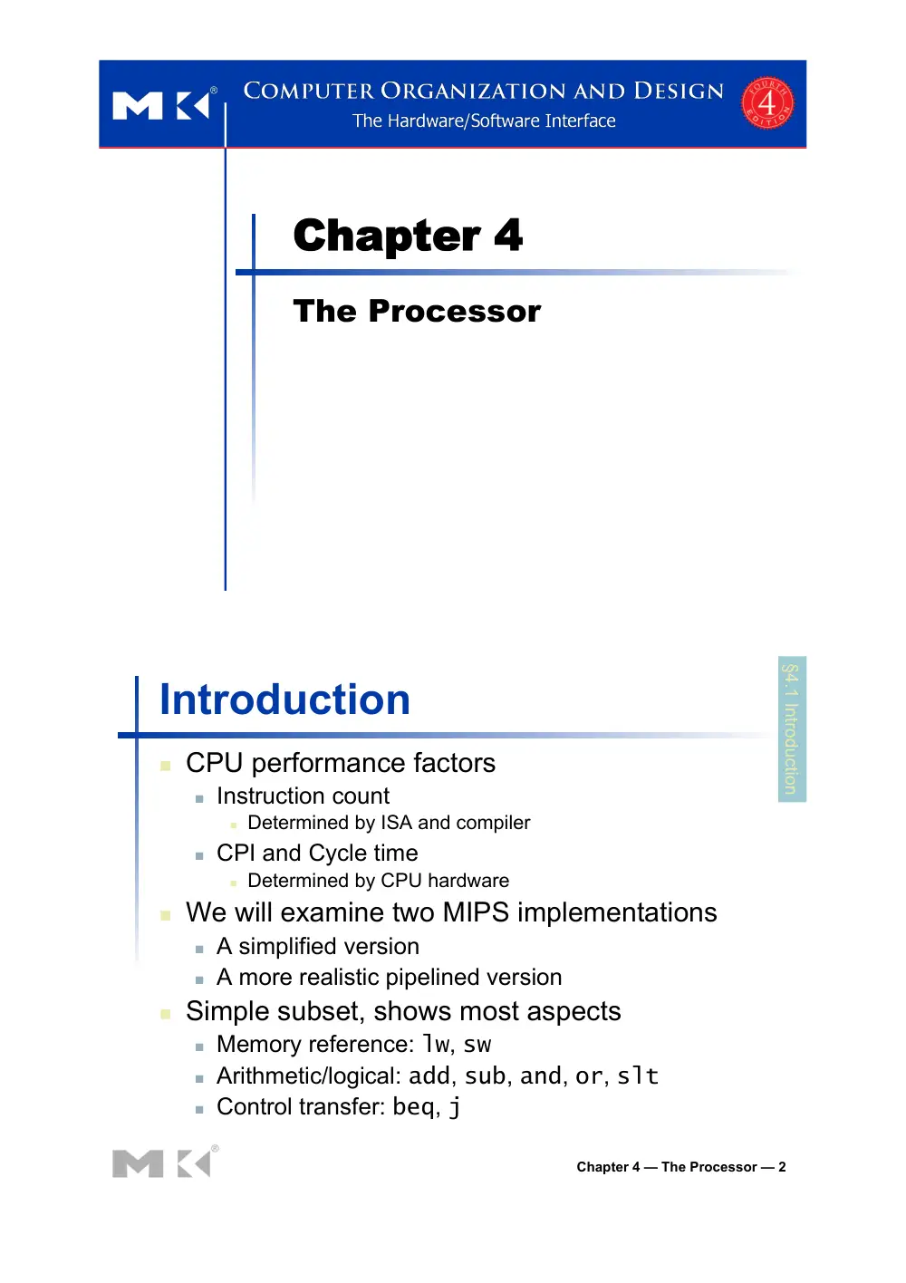
Chapter 4
The Processor
Chapter 4 — The Processor — 2
Introduction
! CPU performance factors
! Instruction count
! Determined by ISA and compiler
! CPI and Cycle time
! Determined by CPU hardware
! We will examine two MIPS implementations
! A simplified version
! A more realistic pipelined version
! Simple subset, shows most aspects
! Memory reference: lw, sw
! Arithmetic/logical: add, sub, and, or, slt
! Control transfer: beq, j
§4.1 Introduction
Chapter 4 — The Processor — 3
Instruction Execution
! PC → instruction memory, fetch instruction
! Register numbers → register file, read registers
! Depending on instruction class
! Use ALU to calculate
! Arithmetic result
! Memory address for load/store
! Branch target address
! Access data memory for load/store
! PC ← target address or PC + 4
Chapter 4 — The Processor — 4
CPU Overview
Chapter 4 — The Processor — 5
Multiplexers
! Can’t just join
wires together
! Use multiplexers
Chapter 4 — The Processor — 6
Control
Chapter 4 — The Processor — 7
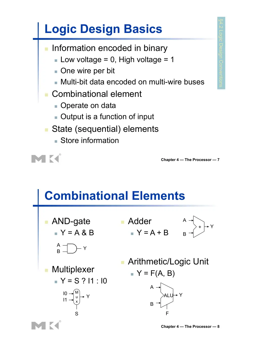
Logic Design Basics
§4.2 Logic Design Conventions
! Information encoded in binary
! Low voltage = 0, High voltage = 1
! One wire per bit
! Multi-bit data encoded on multi-wire buses
! Combinational element
! Operate on data
! Output is a function of input
! State (sequential) elements
! Store information
Chapter 4 — The Processor — 8
Combinational Elements
! AND-gate
! Y = A & B
A
B
Y
I0
I1
Y
M
u
x
S
! Multiplexer
! Y = S ? I1 : I0
A
B
Y
+
A
B
Y
ALU
F
! Adder
! Y = A + B
! Arithmetic/Logic Unit
! Y = F(A, B)
Chapter 4 — The Processor — 9
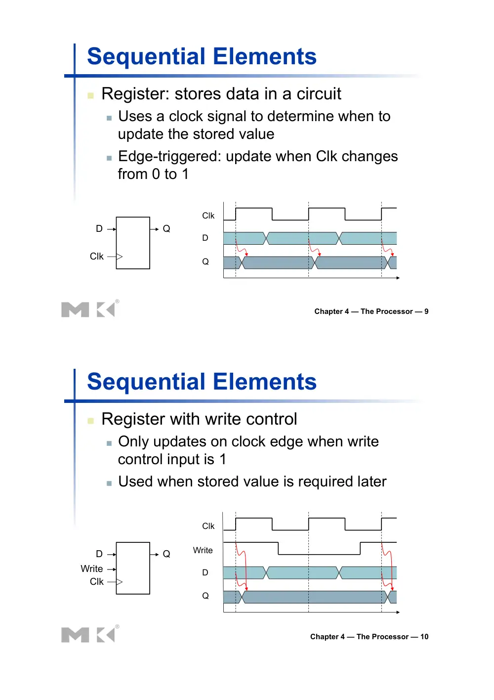
Sequential Elements
! Register: stores data in a circuit
! Uses a clock signal to determine when to
update the stored value
! Edge-triggered: update when Clk changes
from 0 to 1
D
Clk
Q
Clk
D
Q
Chapter 4 — The Processor — 10
Sequential Elements
! Register with write control
! Only updates on clock edge when write
control input is 1
! Used when stored value is required later
D
Clk
Q
Write
Write
D
Q
Clk
Chapter 4 — The Processor — 11
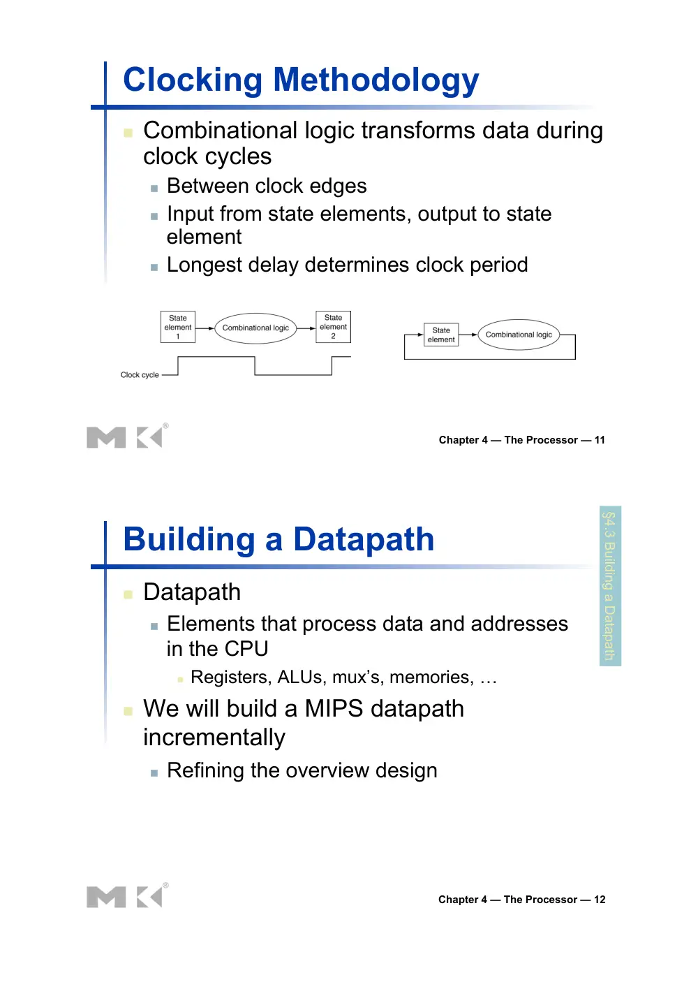
Clocking Methodology
! Combinational logic transforms data during
clock cycles
! Between clock edges
! Input from state elements, output to state
element
! Longest delay determines clock period
Chapter 4 — The Processor — 12
Building a Datapath
! Datapath
! Elements that process data and addresses
in the CPU
! Registers, ALUs, mux’s, memories, …
! We will build a MIPS datapath
incrementally
! Refining the overview design
§4.3 Building a Datapath
Chapter 4 — The Processor — 13
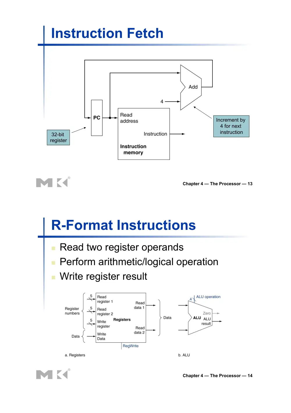
Instruction Fetch
32-bit
register
Increment by
4 for next
instruction
Chapter 4 — The Processor — 14
R-Format Instructions
! Read two register operands
! Perform arithmetic/logical operation
! Write register result
Chapter 4 — The Processor — 15
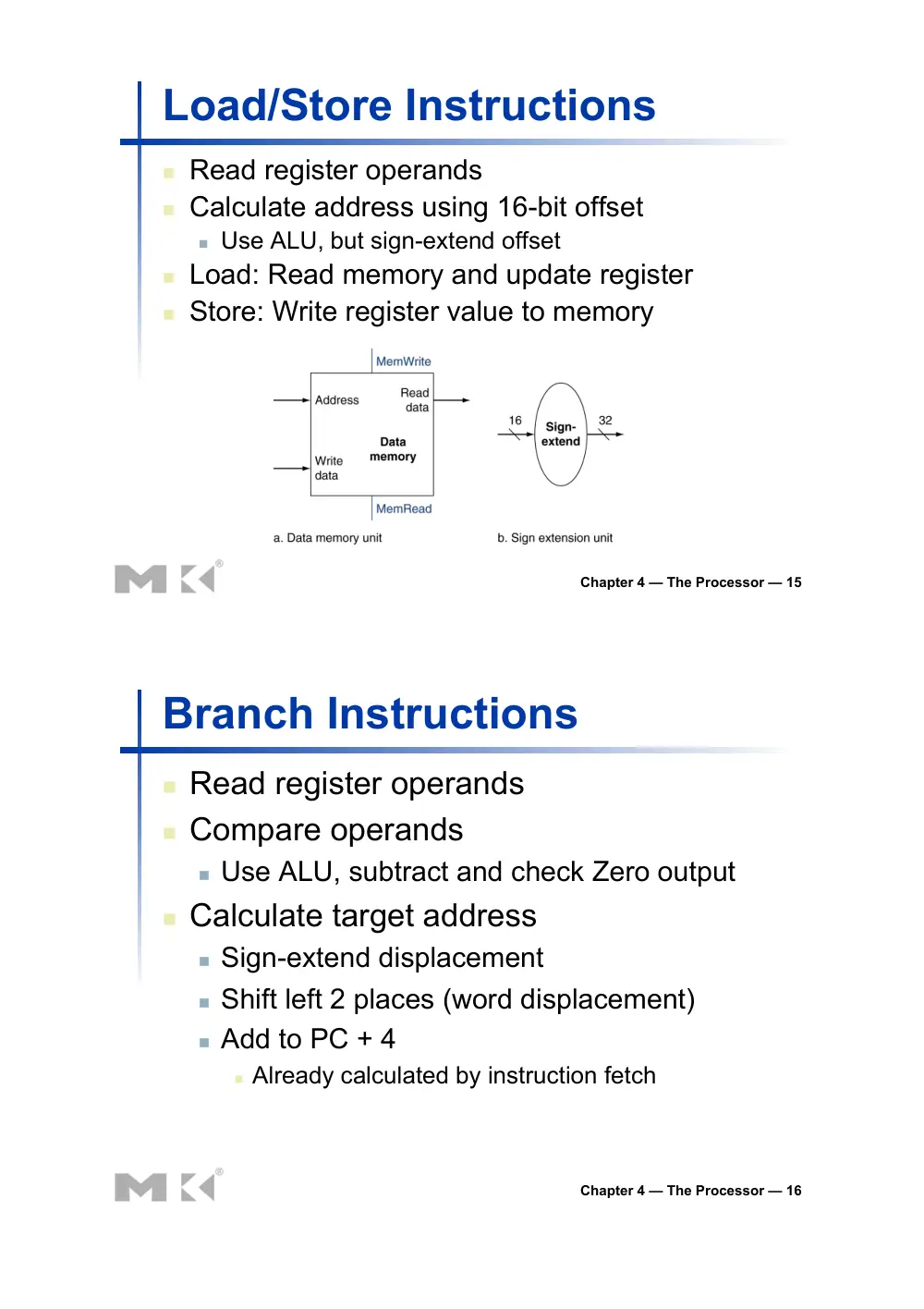
Load/Store Instructions
! Read register operands
! Calculate address using 16-bit offset
! Use ALU, but sign-extend offset
! Load: Read memory and update register
! Store: Write register value to memory
Chapter 4 — The Processor — 16
Branch Instructions
! Read register operands
! Compare operands
! Use ALU, subtract and check Zero output
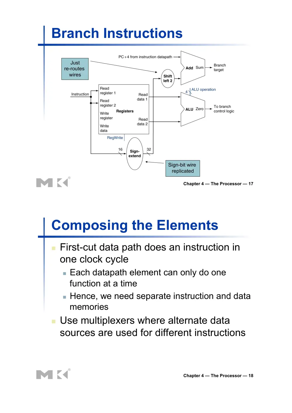
! Calculate target address
! Sign-extend displacement
! Shift left 2 places (word displacement)
! Add to PC + 4
! Already calculated by instruction fetch
Chapter 4 — The Processor — 17
Branch Instructions
Just
re-routes
wires
Sign-bit wire
replicated
Chapter 4 — The Processor — 18
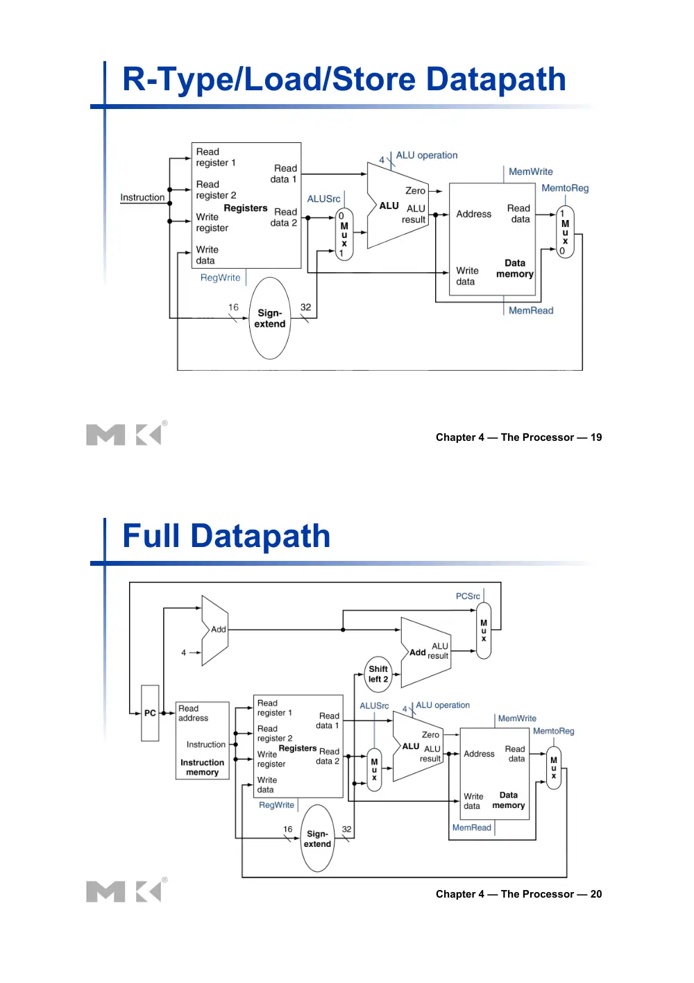
Composing the Elements
! First-cut data path does an instruction in
one clock cycle
! Each datapath element can only do one
function at a time
! Hence, we need separate instruction and data
memories
! Use multiplexers where alternate data
sources are used for different instructions
Chapter 4 — The Processor — 19
R-Type/Load/Store Datapath
Chapter 4 — The Processor — 20
Full Datapath
Chapter 4 — The Processor — 21
ALU Control
! ALU used for
! Load/Store: F = add
! Branch: F = subtract
! R-type: F depends on funct field
§4.4 A Simple Implementation Scheme
ALU control
Function
0000
AND
0001
OR
0010
add
0110
subtract
0111
set-on-less-than
1100
NOR
Chapter 4 — The Processor — 22
ALU Control
! Assume 2-bit ALUOp derived from opcode
! Combinational logic derives ALU control
opcode
ALUOp Operation
funct
ALU function
ALU control
lw
00
load word
XXXXXX add
0010
sw
00
store word
XXXXXX add
0010
beq
01
branch equal
XXXXXX subtract
0110
R-type
10
add
100000
add
0010
subtract
100010
subtract
0110
AND
100100
AND
0000
OR
100101
OR
0001
set-on-less-than
101010
set-on-less-than
0111
Chapter 4 — The Processor — 23
The Main Control Unit
! Control signals derived from instruction
0
rs
rt
rd
shamt
funct
31:26
5:0
25:21
20:16
15:11
10:6
35 or 43
rs
rt
address
31:26
25:21
20:16
15:0
4
rs
rt
address
31:26
25:21
20:16
15:0
R-type
Load/
Store
Branch
opcode
always
read
read,
except
for load
write for
R-type
and load
sign-extend
and add
Chapter 4 — The Processor — 24
Datapath With Control
Chapter 4 — The Processor — 25
R-Type Instruction
Chapter 4 — The Processor — 26
Load Instruction
Chapter 4 — The Processor — 27
Branch-on-Equal Instruction
Chapter 4 — The Processor — 28
Implementing Jumps
! Jump uses word address
! Update PC with concatenation of
! Top 4 bits of old PC
! 26-bit jump address
! 00
! Need an extra control signal decoded from
opcode
2
address
31:26
25:0
Jump
Chapter 4 — The Processor — 29
Datapath With Jumps Added
Chapter 4 — The Processor — 30
Performance Issues
! Longest delay determines clock period
! Critical path: load instruction
! Instruction memory → register file → ALU →
data memory → register file
! Not feasible to vary period for different
instructions
! Violates design principle
! Making the common case fast
! We will improve performance by pipelining
Chapter 4 — The Processor — 31
Pipelining Analogy
! Pipelined laundry: overlapping execution
! Parallelism improves performance
§4.5 An Overview of Pipelining
! Four loads:
! Speedup
= 8/3.5 = 2.3
! Non-stop:
! Speedup
= 2n/0.5n + 1.5 ≈ 4
= number of stages
Chapter 4 — The Processor — 32
MIPS Pipeline
!
Five stages, one step per stage
1. IF: Instruction fetch from memory
2. ID: Instruction decode & register read
3. EX: Execute operation or calculate address
4. MEM: Access memory operand
5. WB: Write result back to register
Chapter 4 — The Processor — 33
Pipeline Performance
! Assume time for stages is
! 100ps for register read or write
! 200ps for other stages
! Compare pipelined datapath with single-cycle
datapath
Instr
Instr fetch Register
read
ALU op
Memory
access
Register
write
Total time
lw
200ps
100 ps
200ps
200ps
100 ps
800ps
sw
200ps
100 ps
200ps
200ps
700ps
R-format
200ps
100 ps
200ps
100 ps
600ps
beq
200ps
100 ps
200ps
500ps
Chapter 4 — The Processor — 34
Pipeline Performance
Single-cycle (Tc= 800ps)
Pipelined (Tc= 200ps)
Chapter 4 — The Processor — 35
Pipeline Speedup
! If all stages are balanced
! i.e., all take the same time
! Time between instructionspipelined
= Time between instructionsnonpipelined
Number of stages
! If not balanced, speedup is less
! Speedup due to increased throughput
! Latency (time for each instruction) does not
decrease
Chapter 4 — The Processor — 36
Pipelining and ISA Design
! MIPS ISA designed for pipelining
! All instructions are 32-bits
! Easier to fetch and decode in one cycle
! c.f. x86: 1- to 17-byte instructions
! Few and regular instruction formats
! Can decode and read registers in one step
! Load/store addressing
! Can calculate address in 3rd stage, access memory
in 4th stage
! Alignment of memory operands
! Memory access takes only one cycle
Chapter 4 — The Processor — 37
Hazards
! Situations that prevent starting the next
instruction in the next cycle
! Structure hazards
! A required resource is busy
! Data hazard
! Need to wait for previous instruction to
complete its data read/write
! Control hazard
! Deciding on control action depends on
previous instruction
Chapter 4 — The Processor — 38
Structure Hazards
! Conflict for use of a resource
! In MIPS pipeline with a single memory
! Load/store requires data access
! Instruction fetch would have to stall for that
cycle
! Would cause a pipeline “bubble”
! Hence, pipelined datapaths require
separate instruction/data memories
! Or separate instruction/data caches
Chapter 4 — The Processor — 39
Data Hazards
! An instruction depends on completion of
data access by a previous instruction
! add $s0, $t0, $t1
sub $t2, $s0, $t3
Chapter 4 — The Processor — 40
Forwarding (aka Bypassing)
! Use result when it is computed
! Don’t wait for it to be stored in a register
! Requires extra connections in the datapath
Chapter 4 — The Processor — 41
Load-Use Data Hazard
! Can’t always avoid stalls by forwarding
! If value not computed when needed
! Can’t forward backward in time!
Chapter 4 — The Processor — 42
Code Scheduling to Avoid Stalls
! Reorder code to avoid use of load result in
the next instruction
! C code for A = B + E; C = B + F;
lw $t1, 0($t0)
lw $t2, 4($t0)
add $t3, $t1, $t2
sw $t3, 12($t0)
lw $t4, 8($t0)
add $t5, $t1, $t4
sw $t5, 16($t0)
stall
stall
lw $t1, 0($t0)
lw $t2, 4($t0)
lw $t4, 8($t0)
add $t3, $t1, $t2
sw $t3, 12($t0)
add $t5, $t1, $t4
sw $t5, 16($t0)
11 cycles
13 cycles
Chapter 4 — The Processor — 43
Control Hazards
! Branch determines flow of control
! Fetching next instruction depends on branch
outcome
! Pipeline can’t always fetch correct instruction
! Still working on ID stage of branch
! In MIPS pipeline
! Need to compare registers and compute
target early in the pipeline
! Add hardware to do it in ID stage
Chapter 4 — The Processor — 44
Stall on Branch
! Wait until branch outcome determined
before fetching next instruction
Chapter 4 — The Processor — 45
Branch Prediction
! Longer pipelines can’t readily determine
branch outcome early
! Stall penalty becomes unacceptable
! Predict outcome of branch
! Only stall if prediction is wrong
! In MIPS pipeline
! Can predict branches not taken
! Fetch instruction after branch, with no delay
Chapter 4 — The Processor — 46
MIPS with Predict Not Taken
Prediction
correct
Prediction
incorrect
Chapter 4 — The Processor — 47
More-Realistic Branch Prediction
! Static branch prediction
! Based on typical branch behavior
! Example: loop and if-statement branches
! Predict backward branches taken
! Predict forward branches not taken
! Dynamic branch prediction
! Hardware measures actual branch behavior
! e.g., record recent history of each branch
! Assume future behavior will continue the trend
! When wrong, stall while re-fetching, and update history
Chapter 4 — The Processor — 48
Pipeline Summary
! Pipelining improves performance by
increasing instruction throughput
! Executes multiple instructions in parallel
! Each instruction has the same latency
! Subject to hazards
! Structure, data, control
! Instruction set design affects complexity of
pipeline implementation
The BIG Picture