
MEE 320 Chapter 1, Spring 2018
Lebanese American University · Strength of Material · 44 pages · Dr. Carine Habchi




Showing the first 10 of 44 pages. Download the PDF to see all of it.
More MEE 320 files
Show the text of this chapter
MEE 320: Strength of Materials
Chapter 1
Concept of Stress
MEE 320: Strength of Materials
Concept of Stress
Objectives
The main objective of the study of mechanics of materials is to provide the
future engineer with the means of analyzing and designing various machines
and load bearing structures.
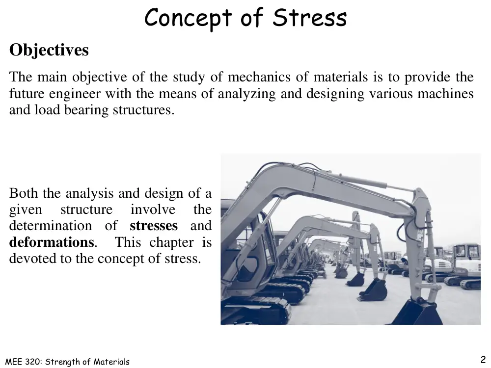
Both the analysis and design of a
given
structure
involve
the
determination of stresses and
deformations. This chapter is
devoted to the concept of stress.
2
MEE 320: Strength of Materials
Statics Review
Example: Consider the structure shown below and assume that it is
designed to support a 30 kN load. The structure consists of a boom and rod
joined by pins (zero moment connections) at the junctions and supports.
Plan: Perform a static analysis to
determine the internal force in each
structural member and the reaction
forces at the supports
3
MEE 320: Strength of Materials
Statics Review
FBD: free body diagram
Structure is detached from supports
loads and reaction forces are indicated
Ay and Cy cannot be determined from these
equations need to find new equations
kN
30
kN 0
30
0
kN
40
0
kN
40
kN 8.0 m
30
6.0 m
0
y
y
y
y
y
x
x
x
x
x
x
x
C
C
A
C
A
F
A
C
C
A
F
A
A
M
Conditions for static equilibrium
4
MEE 320: Strength of Materials
Component Free-Body Diagram
5
In addition to the complete structure, each component
must satisfy the conditions for static equilibrium
kN
30
kN
40
kN
40
y
x
x
C
C
A
Reaction forces are directed along boom and rod
0
8.0 m
0
y
y
B
A
A
M
Consider the FBD for the boom:
Now the structure equilibrium equation yields
MEE 320: Strength of Materials
Method of Joints
6
The boom and rod are 2-force members, i.e., the members are
subjected to only two forces which are applied at member ends
kN
50
kN
40
3
kN
30
5
4
0
BC
AB
BC
AB
B
F
F
F
F
F
Joints must satisfy the conditions for static
equilibrium which may be expressed in the form
of a force triangle:
For equilibrium, the forces must be parallel to an
axis passing through the force application points,
equal in magnitude, and in opposite directions
MEE 320: Strength of Materials
Definition: Stress
7
Stress : in a member, stress is defined as force per unit area, or intensity
of the forces distributed over a given section.
A
P
Positive stress: member in tension
Negative stress: member in compression
Units:
P in N
A in m2
σ in N/m2 = Pa (Pascal)
MEE 320: Strength of Materials
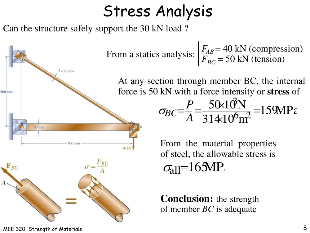
Stress Analysis
8
Conclusion: the strength
of member BC is adequate
MPa
all165
From the material properties
of steel, the allowable stress is
Can the structure safely support the 30 kN load ?
MPa
159
10 m
314
10N
50
2
6-
3
A
BC P
At any section through member BC, the internal
force is 50 kN with a force intensity or stress of
FAB = 40 kN (compression)
From a statics analysis: FBC = 50 kN (tension)
MEE 320: Strength of Materials
Design
9
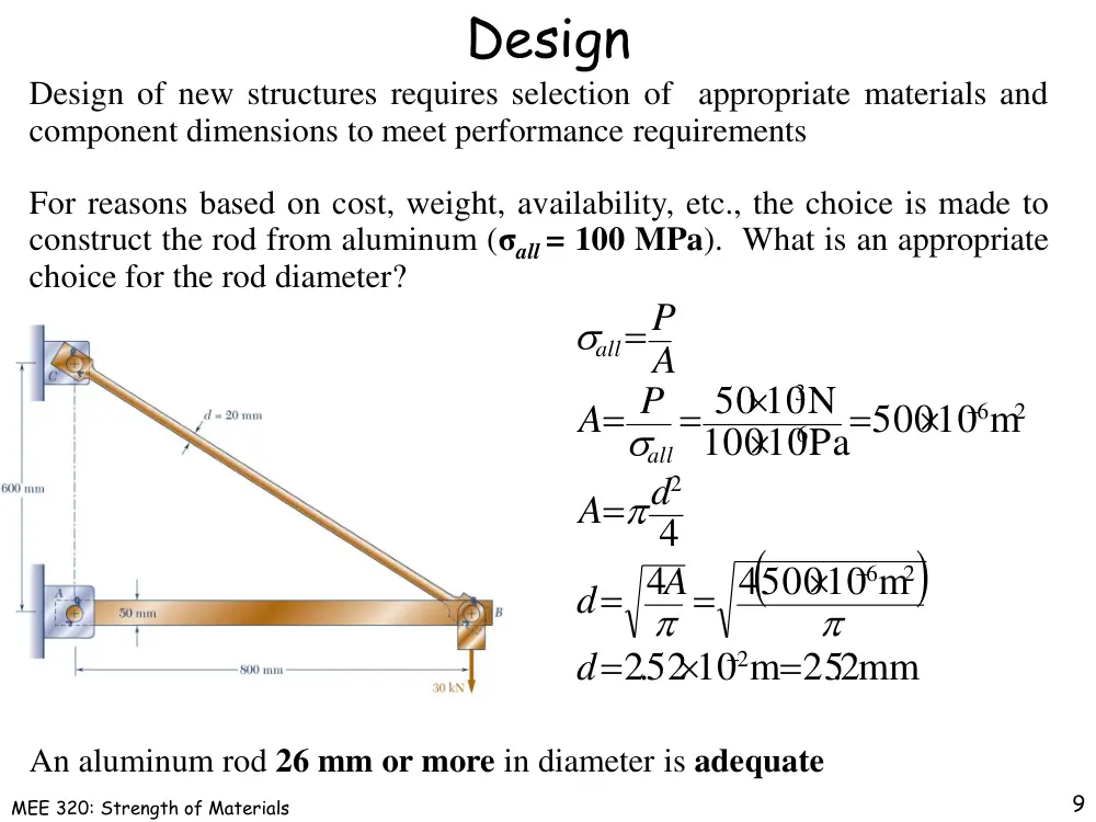
Design of new structures requires selection of appropriate materials and
component dimensions to meet performance requirements
For reasons based on cost, weight, availability, etc., the choice is made to
construct the rod from aluminum (σall = 100 MPa). What is an appropriate
choice for the rod diameter?
52 10 m 252. mm
.2
450010 m
4
4
10Pa 50010 m
100
10N
50
2
2
6
2
2
6
6
3
d
A
d
d
A
P
A
A
P
all
all
An aluminum rod 26 mm or more in diameter is adequate
MEE 320: Strength of Materials
Axial Loading: Normal Stress
10
The normal stress at a particular point may not
be equal to the average stress but the resultant of
the stress distribution must satisfy
A
ave
dA
dF
A
P
The resultant of the internal forces for an axially loaded member
is normal to a section cut perpendicular to the member axis.
A
P
A
F
ave
A
0
lim
The force intensity on that section
is defined as the normal stress.
The detailed distribution of stress is statically
indeterminate, i.e., cannot be found from statics
alone.
MEE 320: Strength of Materials
Centric & Eccentric Loading
11
If a two-force member is eccentrically
loaded, then the resultant of the stress
distribution in a section must yield an axial
force and a moment.
The stress distributions in eccentrically loaded
members cannot be uniform or symmetric.
A uniform distribution of stress in a section infers that the line of
action for the resultant of the internal forces passes through the
centroid of the section.
A uniform distribution of stress is only possible if the concentrated
loads on the end sections of two-force members are applied at the
section centroids. This is referred to as centric loading.
MEE 320: Strength of Materials
Shearing Stress
12
Forces P and P’ are applied transversely to the member AB.
A
aveP
The corresponding average shear stress is,
Corresponding internal forces act in the plane of
section C and are called shearing forces. The resultant
of the internal shear force distribution is defined as the
shear of the section and is equal to the load P.
Shear stress distribution varies from zero at the
member surfaces to maximum values that may
be much larger than the average value.
The shear stress distribution cannot be
assumed to be uniform.
MEE 320: Strength of Materials
Shearing Stress Examples
13
A
F
A
aveP
Single Shear
A
F
A
P
2
ave
Double Shear
MEE 320: Strength of Materials
Bearing Stress in Connections
14
Bolts, rivets, and pins create stresses
on the points of contact or bearing
surfaces of the members they connect.
td
P
A
b P
Corresponding average force intensity
is called the bearing stress,
The resultant of the force distribution
on the surface is equal and opposite to
the force exerted on the pin.
MEE 320: Strength of Materials
Procedure for Analysis
15
The statement of the problem should be clear and precise. It should contain
the given data and indicate what information is required. A simplified
drawing showing all essential quantities involved should be included.
1.
Write the equilibrium equations of the system, this will require the
drawing of one or several FBDs.
2.
Determine the reactions at supports and internal forces and couples.
3.
Compute the required stresses and deformations.
4.
After the answer has been obtained, it should be carefully checked. It can
be done by substituting the numerical values obtained into an equation
which has not yet been used and verifying that the equation is satisfied.
MEE 320: Strength of Materials
Stress Analysis & Design Example
16
Example: determine the stresses in the
members and connections of the structure shown.
Must consider maximum normal
stresses in AB and BC, and the
shearing stress and bearing stress
at each pinned connection
From a statics analysis:
FAB = 40 kN (compression)
FBC = 50 kN (tension)
MEE 320: Strength of Materials
Rod & Boom Normal Stresses
17
The rod is in tension with an axial force of P = 50 kN
and circular cross-sectional area ABC = 314×10-6m2
The boom is in compression with an axial force of 40 kN and average
normal stress of –26.7 MPa. The minimum area sections at the boom ends
are unstressed since the boom is in compression.
MPa
167
10 m
300
10
50
mm 30010 m
mm 25
mm40
20
2
6
3
,
2
6
N
A
P
A
BCend
At the flattened rod ends, the smallest cross-
sectional area occurs at the pin centerline,
At the rod center, the average normal stress in
the circular cross-section is σBC = +159 MPa.
MEE 320: Strength of Materials
Pin Shearing Stresses
18
The cross-sectional area for pins at A, B, and C,
6 2
2
2
49110 m
2
mm
25
r
A
MPa
102
10 m
491
10N
50
6 2
3
,
A
Cave P
The force on the pin at C is equal to the
force exerted by the rod BC,
The pin at A is in double shear with a
total force equal to the force exerted by
the boom AB,
407. MPa
10 m
491
kN
20
6 2
,
A
Aave P
MEE 320: Strength of Materials
Pin Shearing Stresses
19
Divide the pin at B into sections to determine the section with the largest
shear force
kN
15
EP
509. MPa
10 m
491
kN
25
6 2
,
A
Bave PG
Evaluate the corresponding average shearing stress,
(larges
kN
GP 25
MEE 320: Strength of Materials
Pin Bearing Stresses
20
To determine the bearing stress at A in the boom
AB, we have t = 30 mm and d = 25 mm,
mm 533. MPa
mm25
30
kN
40
td
P
b
To determine the bearing stress at A in the bracket,
we have t = 2(25 mm) = 50 mm and d = 25 mm,
mm 320. MPa
mm25
50
kN
40
td
P
b
MEE 320: Strength of Materials
Example 1
21
1-4: Two solid cylindrical rods AB and BC are welded together at B and
loaded as shown. Knowing that d1=50 mm and d2=30 mm, find the average
normal stress at the midsection of (a) rod AB, (b) rod BC
MEE 320: Strength of Materials
Example 2
22
1-7: Each of the four vertical links has an 8×36-mm uniform rectangular cross
section and each of the four pins has a 16-mm diameter. Determine the
maximum value of the average normal stress in the links connecting (a) points
B and D, (b) points C and E.
MEE 320: Strength of Materials
Example 2
23
MEE 320: Strength of Materials
Example 3
24
1-17: When the force P reaches 8 kN, the wooden specimen shown failed in
shear along the surface indicated by the dashed line. Determine the average
shearing stress along that surface at the time of failure.
MEE 320: Strength of Materials
Example 3
25
MEE 320: Strength of Materials
Example 4
26
1-25: Knowing that θ = 40° and P = 9 kN, determine (a) the smallest
allowable diameter of the pin at B if the average shearing stress in the pin is
not to exceed 120 MPa, (b) the corresponding average bearing stress in
member AB at B, (c) the corresponding average bearing stress in each of the
support brackets at B.
MEE 320: Strength of Materials
Example 4
27
MEE 320: Strength of Materials
Example 4
28
MEE 320: Strength of Materials
Stress in Two Force Members
29
We will show that either axial or transverse
forces may produce both normal and shear
stresses with respect to a plane other than
one cut perpendicular to the member axis.
Axial forces on a two force member result
in only normal stresses on a plane cut
perpendicular to the member axis.
Transverse forces on bolts and pins result
in only shear stresses on the plane
perpendicular to bolt or pin axis.
MEE 320: Strength of Materials
Stress on an Oblique Plane
30
Pass a section through the member forming
an angle θ with the normal plane.
sin cos
cos
sin
cos
cos
cos
0
0
2
0
0
A
P
A
P
A
V
A
P
A
P
A
F
The average normal and shear stresses on the
oblique plane are
sin
cos
V P
F P
Resolve P into components normal and
tangential to the oblique section,
From equilibrium conditions, the distributed
forces (stresses) on the plane must be
equivalent to the force P.
MEE 320: Strength of Materials
Maximum Stresses
31
The maximum normal stress occurs when the
reference plane is perpendicular to the member axis,
0
,
0
m
A
P
The maximum shear stress occurs for a plane at
±45o with respect to the axis,
0
0
45 2
sin45cos
A
P
A
P
m
sin cos
cos
0
2
0
A
P
A
P
Normal and shearing stresses on an oblique plane
MEE 320: Strength of Materials
Example 5
32
1-30: Two wooden members of uniform rectangular cross section are joined
by the simple glued scarf splice shown. Knowing that the maximum allowable
shearing stress in the glued splice is 620 kPa, determine (a) the largest load P
that can be safely applied, (b) the corresponding tensile stress in the splice.
MEE 320: Strength of Materials
Example 5
33
MEE 320: Strength of Materials
Stress Under General Loadings
34
A member subjected to a general combination of
loads is cut into two segments by a plane passing
through Q. The distribution of internal force
components may be defined as,
normal force acting on a small area ΔA
shearing force acting on a small area ΔA
Fx
x
z
x
y
x
V
V
V
Vx
yVx
zVx
component parallel to the y-axis
component parallel to the z-axis
MEE 320: Strength of Materials
Stress Under General Loadings
35
For equilibrium, an equal and opposite internal force and stress
distribution must be exerted on the other segment of the member.
A
V
A
V
A
F
xz
A
xz
xy
A
xy
x
A
x
lim
lim
lim
0
0
0
The distribution of internal stress
components may be defined as,
xz
xy
The y component of the shear stress exerted on the face
perpendicular to the x-axis
The z component of the shear stress exerted on the face
perpendicular to the x-axis
MEE 320: Strength of Materials
State of Stress
36
Stress components are defined for the
planes cut parallel to the x, y and z axes.
For equilibrium, equal and opposite
stresses are exerted on the hidden planes.
The combination of forces generated by
the stresses must satisfy the conditions for
equilibrium:
0
0
z
y
x
z
y
x
M
M
M
F
F
F
Stress components are defined for the
planes cut parallel to the x, y and z axes.
For equilibrium, equal and opposite
stresses are exerted on the hidden planes.
MEE 320: Strength of Materials
State of Stress
37
It follows that only 6 components of stress are
required to define the complete state of stress
yx
xy
yx
xy
z
Aa
Aa
M
0
zx
xz
zy
yz
Consider the moments about the z axis:
zx
yz
z xy
y
x
and
,
,
,
,
Similarly
MEE 320: Strength of Materials
Factor of Safety
38
stress
allowable
stress
ultimate
of safety
Factor
all
u
FS
FS
Structural members or machines must be designed such that the working
stresses are less than the ultimate strength of the material.
Factor of safety considerations:
• Uncertainty in material properties
• Uncertainty of loadings
• Uncertainty of analyses
• Number of loading cycles
• Types of failure
• Maintenance requirements
• Deterioration effects
MEE 320: Strength of Materials
Example 6
39
1-38: Link BC is 6 mm thick, has a width w = 25 mm, and is made of a steel
with a 480 MPa ultimate strength in tension. What was the safety factor used if
the structure shown was designed to support a 16 kN load P?
MEE 320: Strength of Materials
Example 6
40
MEE 320: Strength of Materials
Example 7
41
1-46: Three steel bolts are to be used to attach
the steel plate shown to a wooden beam. Knowing
that the plate will support a 110 kN load, that the
ultimate shearing stress for the steel used is 360
MPa, and that a factor of safety of 3.35 is desired,
determine the required diameter of the bolts.
MEE 320: Strength of Materials
Example 8
42
1-55: In the structure shown, an 8 mm diameter pin is used at A, and 12-mm-
diameter pins are used at B and D. Knowing that the ultimate shearing stress is
100 MPa at all connections and that the ultimate normal stress is 250 MPa in
each of the two links joining B and D, determine the allowable load P if an
overall factor of safety of 3.0 is desired.
MEE 320: Strength of Materials
Example 8
43
MEE 320: Strength of Materials
Example 8
44