
MEE 320 Chapter 2, Spring 2018
Lebanese American University · Strength of Material · 44 pages · Dr. Carine Habchi

Showing the first 10 of 44 pages. Download the PDF to see all of it.
More MEE 320 files
Show the text of this chapter
MEE 320: Strength of Materials
Chapter 2
Stress and Strain
Axial loading
MEE 320: Strength of Materials
Stress & Strain: Axial Loading
Suitability of a structure or machine may depend on the deformations in the
structure as well as the stresses induced under loading. Statics analyses
alone are not sufficient.
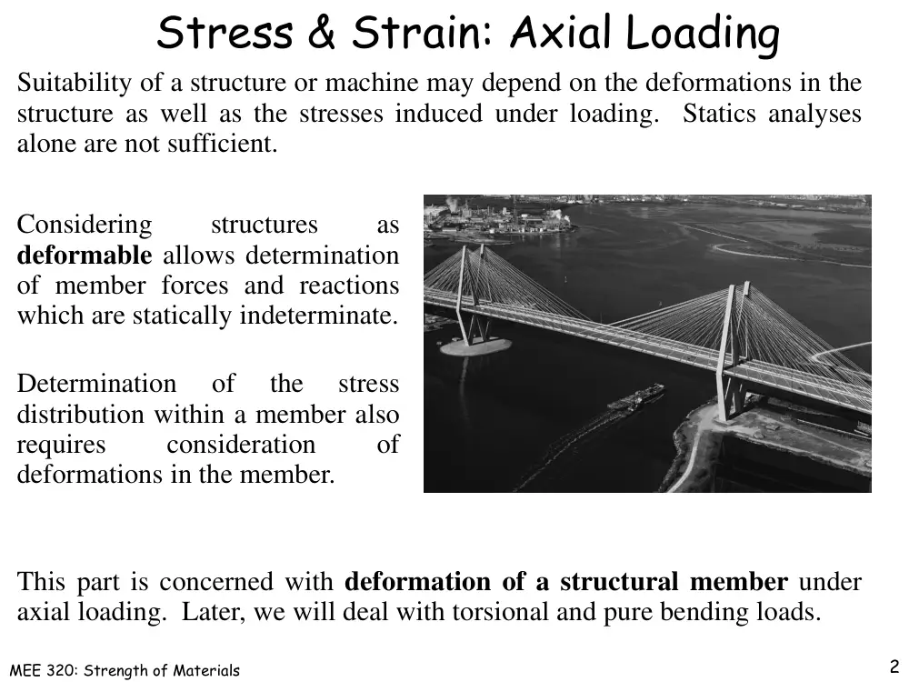
Considering
structures
as
deformable allows determination
of member forces and reactions
which are statically indeterminate.
Determination
of
the
stress
distribution within a member also
requires
consideration
of
deformations in the member.
This part is concerned with deformation of a structural member under
axial loading. Later, we will deal with torsional and pure bending loads.
2
MEE 320: Strength of Materials
Normal Strain
A
P
L
stress
normal
strain
normal
3
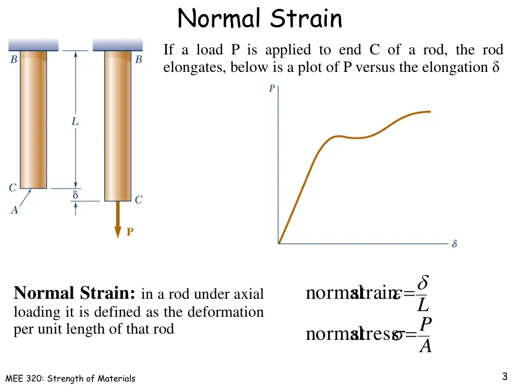
Normal Strain: in a rod under axial
loading it is defined as the deformation
per unit length of that rod
If a load P is applied to end C of a rod, the rod
elongates, below is a plot of P versus the elongation δ
MEE 320: Strength of Materials
Normal Strain
dx
d
x
x
0
lim
4
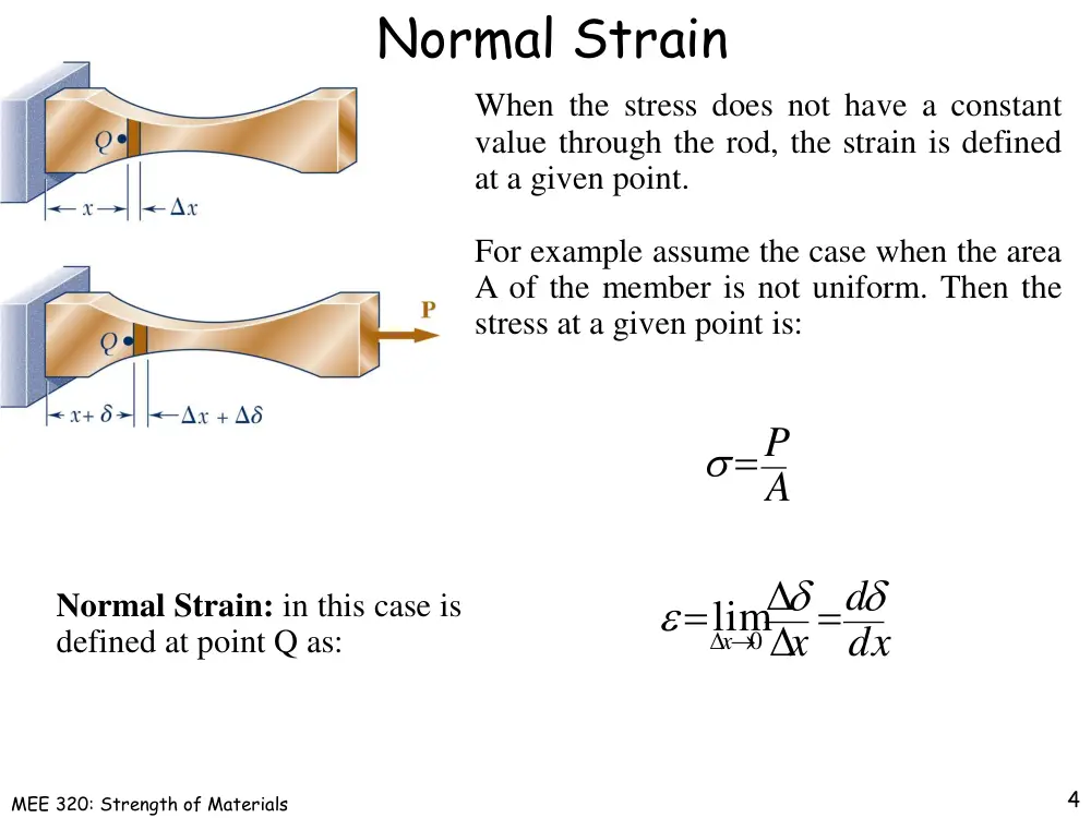
When the stress does not have a constant
value through the rod, the strain is defined
at a given point.
For example assume the case when the area
A of the member is not uniform. Then the
stress at a given point is:
A
P
Normal Strain: in this case is
defined at point Q as:
MEE 320: Strength of Materials
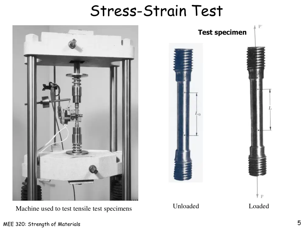
Stress-Strain Test
Machine used to test tensile test specimens
Loaded
5
Test specimen
Unloaded
MEE 320: Strength of Materials
Ductile Materials
6
Ductile materials: characterized by their ability to deform plastically
before rupture. Ex: steel, aluminum, copper
σY : yield strength, stress at which yield is initiated,
elastic plastic transition
σU : ultimate strength, correspond to the maximum
load applied to the specimen
σB : Breaking strength, correspond to rupture
MEE 320: Strength of Materials
Ductile Materials
7
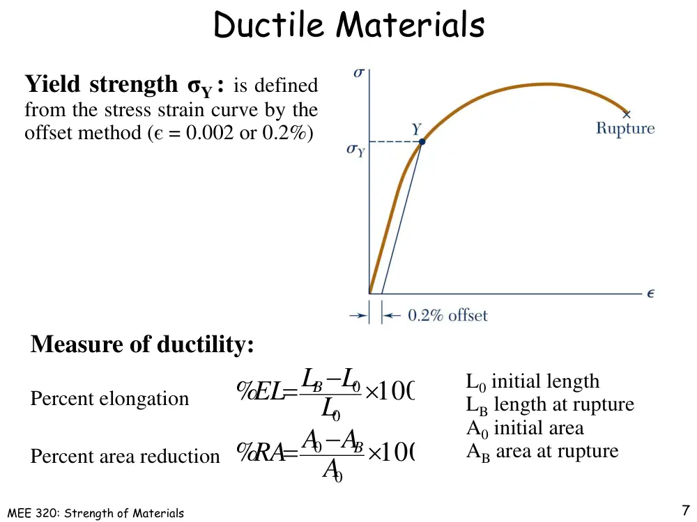
Yield strength σY : is defined
from the stress strain curve by the
offset method (є = 0.002 or 0.2%)
Measure of ductility:
100
%
100
%
0
0
0
0
A
A
A
RA
L
L
L
EL
B
B
Percent elongation
Percent area reduction
L0 initial length
LB length at rupture
A0 initial area
AB area at rupture
MEE 320: Strength of Materials
Brittle Materials
8
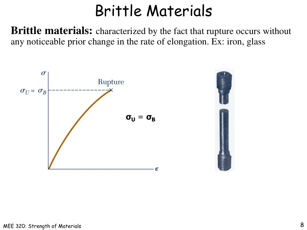
Brittle materials: characterized by the fact that rupture occurs without
any noticeable prior change in the rate of elongation. Ex: iron, glass
σU = σB
MEE 320: Strength of Materials
True stress True strain
9
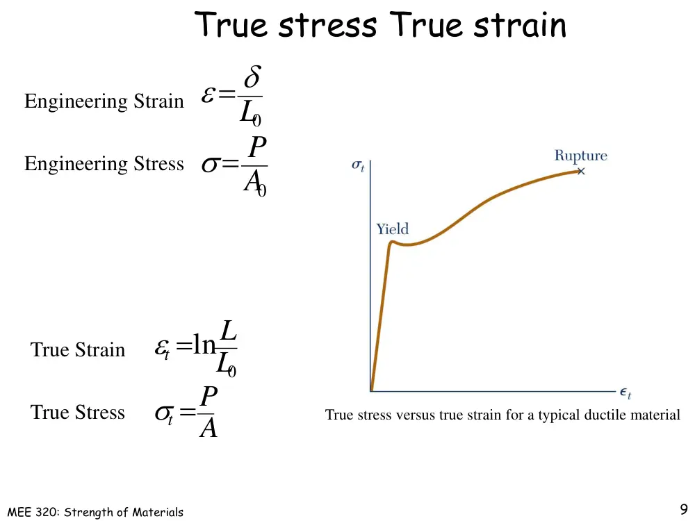
Engineering Strain
Engineering Stress
True stress versus true strain for a typical ductile material
0
0
A
P
L
A
P
L
L
t
t
0
ln
True Strain
True Stress
MEE 320: Strength of Materials
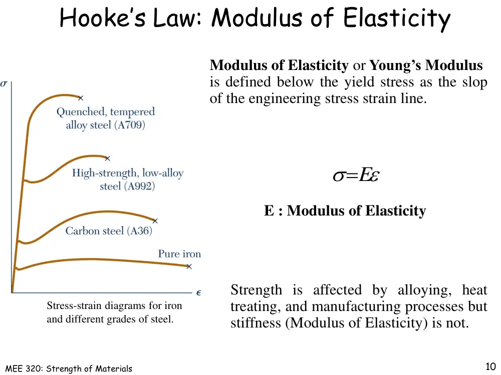
Hooke’s Law: Modulus of Elasticity
E
Strength is affected by alloying, heat
treating, and manufacturing processes but
stiffness (Modulus of Elasticity) is not.
Stress-strain diagrams for iron
and different grades of steel.
10
Modulus of Elasticity or Young’s Modulus
is defined below the yield stress as the slop
of the engineering stress strain line.
E : Modulus of Elasticity
MEE 320: Strength of Materials
Elastic vs. Plastic
If the strain disappears when the stress
is removed, the material is said to
behave elastically.
When the strain does not return to zero
after the stress is removed, the material
is said to behave plastically.
The largest stress for which this occurs
is called the elastic limit.
11
If the member is loaded again after
being loaded and unloaded, the new
loading curve will closely follow the
earlier unloading curve.
MEE 320: Strength of Materials
Fatigue
When the stress is reduced below the
endurance limit, fatigue failures do not
occur for any number of cycles.
A member may fail due to fatigue at stress
levels significantly below the ultimate
strength if subjected to many loading
cycles.
12
Fatigue is the progressive and localized structural damage that occurs when
a material is subjected to cyclic loading in the elastic range of the material.
The fatigue properties are usually shown in a Stress versus Life (number of
cycles to failure) diagram or S-N diagram.
MEE 320: Strength of Materials
Deformations Under Axial Loading
AE L
P
E
E
Assume a member subjected to a centric axial load P
First calculate the normal stress in the member
Then from Hooke’s Law calculate the strain:
The deformation is calculated from the strain
AE
PL
With variations in loading, cross-section or material properties,
i
i
i
i i
E
A
PL
13
A
P
MEE 320: Strength of Materials
Example 1
14
2-3: An 18 m long steel wire of 5-mm diameter is to be used in the
manufacture of a prestressed concrete beam. It is observed that the wire
stretches 45 mm when a tensile force P is applied. Knowing that E = 200
GPa, determine (a) the magnitude of the force P, (b) the corresponding
normal stress in the wire.
MEE 320: Strength of Materials
Example 2
15
2-6: A control rod made of yellow brass must not stretch more than 3 mm
when the tension in the wire is 4 kN. Knowing that E = 105 GPa and that the
maximum allowable normal stress is 180 MPa, determine (a) the smallest
diameter rod that should be used, (b) the corresponding maximum length of
the rod.
MEE 320: Strength of Materials
Example 3
16
2-19: both portions of the rod ABC are made of an
aluminum for which E = 70 GPa. Knowing that the
magnitude of P is 4 KN, determine (a) the value of
Q so that the deflection at A is zero, (b) the
corresponding deflection of B.
MEE 320: Strength of Materials
Example 3
17
MEE 320: Strength of Materials
Example 4
18
2-27: Each of the links AB and CD is
made of aluminum (E = 75 GPa) and has a
cross-sectional area of 258 mm2. Knowing
that they support the rigid member BC,
determine the deflection of point E.
MEE 320: Strength of Materials
Example 4
19
MEE 320: Strength of Materials
Static Indeterminacy
Structures for which internal forces and
reactions cannot be determined from statics
alone are said to be statically indeterminate.
0
2
1
Deformations due to actual loads and redundant
reactions are determined separately and then
added or superposed.
Redundant
reactions
are
replaced
with
unknown loads which along with the other
loads must produce compatible deformations.
A structure will be statically indeterminate
whenever it is held by more supports than are
required to maintain its equilibrium.
20
AE
L
P 1
1
1
AE
L
P 2
2
2
MEE 320: Strength of Materials
Example 5
21
2-37: An axial force of 200 kN is applied to
the assembly shown by means of rigid end
plates. Determine (a) the normal stress in the
aluminum
shell,
(b)
the
corresponding
deformation of the assembly.
MEE 320: Strength of Materials
Example 5
22
MEE 320: Strength of Materials
Example 6
23
2-44: The rigid bar AD is supported by two steel wires of 1.5 mm diameter
(E = 200 GPa) and a pin and bracket at A. Knowing that the wires were
initially taught, determine (a) the additional tension in each wire when a 1.0
kN load P is applied at D, (b) the corresponding deflection of point D.
MEE 320: Strength of Materials
Example 6
24
MEE 320: Strength of Materials
Thermal Strain
Consider a homogeneous rod AB of
uniform cross section, which rests
freely on a smooth horizontal surface.
TL
T
25
When the temperature is raised by ΔT,
the rod elongates by an amount δT
which is proportional to both ΔT and
length of the rod L. Let α be the
coefficient of thermal expansion then
T
T
The thermal strain associated with
the deformation is
In this case no stress is associated
with the thermal strain
MEE 320: Strength of Materials
Thermal Stresses
A temperature change results in a change in
length or thermal strain. There is no stress
associated with the thermal strain unless the
elongation is restrained by the supports.
AE
PL
T L
P
T
Treat the additional support as redundant and
apply the principle of superposition.
0
0
AE
L PL
T
P
T
The thermal deformation and the deformation
from the redundant support must be compatible.
T
E
A
P
T
AE
P
26
MEE 320: Strength of Materials
Example 7
27
2-52: A rod consisting of two cylindrical portions AB and BC is restrained at
both ends. Portion AB is made of brass (Eb =105 GPa, αb = 20.9×10⁻⁶/oC) and
portion BC is made of aluminum (Ea = 72 GPa, αa = 23.9×10⁻⁶/oC). Knowing
that the rod is initially unstressed, determine (a) the normal stresses induced in
portions AB and BC by a temperature rise of 42°C, (b) the corresponding
deflection of point B.
MEE 320: Strength of Materials
Example 7
28
MEE 320: Strength of Materials
Example 8
29
2-58: Knowing that a 0.5 mm gap exists when the temperature is 24°C,
determine (a) the temperature at which the normal stress in the aluminum bar
will be equal to −75 MPa, (b) the corresponding exact length of the aluminum
bar.
MEE 320: Strength of Materials
Example 8
30
MEE 320: Strength of Materials
Poisson’s Ratio
For a slender bar subjected to axial loading:
0
z
y
x
x
E
The elongation in the x-direction is
accompanied by a contraction in the other
directions. Assuming that the material is
isotropic (no directional dependence),
z 0
y
Poisson’s ratio is defined as
x
z
x
y
strain
axial
strain
lateral
31
E
x
x
z
y
MEE 320: Strength of Materials
Generalized Hooke’s Law
For an element subjected to multi-axial loading,
the normal strain components resulting from the
stress components may be determined from the
principle of superposition. This requires:
1) strain
is
linearly
related
to
stress
2) deformations are small
Effect of alone
32
x
E
E
E
x
z
x
y
x
x
Calculate the effect of , and
separately and then add the results
x
y
z
MEE 320: Strength of Materials
Generalized Hooke’s Law
33
E
E
E
y
z
y
y
y
x
E
E
E
z
z
z
y
z
x
Effect of
y
Effect of
z
E
E
E
E
E
E
E
E
E
z
y
x
z
z
y
x
y
z
y
x
x
Principle of
Superposition
MEE 320: Strength of Materials
Shearing Strain
A cubic element subjected to a shear stress τxy
will deform into a rhomboid. The corresponding
shear strain γxy is quantified in terms of the
change in angle between the sides,
xy
xy
f
A plot of shear stress vs. shear strain is similar to
the previous plots of normal stress vs. normal
strain except that the strength values are
approximately half. For small strains,
zx
zx
yz
yz
xy
xy
G
G
G
where G is the modulus of rigidity or shear
modulus.
34
MEE 320: Strength of Materials
Relation Among E, , and G
Young’s modulus: E
2G 1
E
Relation between E, ν and G
35
Poisson ratio: ν
Modulus of rigidity: G
x
x
E
x
z
y
xy Gxy
MEE 320: Strength of Materials
Example 9
36
2-61: A 20 mm diameter rod made of an
experimental plastic is subjected to a tensile force
of magnitude P = 6 kN. Knowing that an
elongation of 14 mm and a decrease in diameter of
0.85 mm are observed in a 150 mm length,
determine the modulus of elasticity, the modulus of
rigidity, and Poisson’s ratio for the material.
MEE 320: Strength of Materials
Example 10
37
2-68: A fabric used in air-inflated structures is subjected to a biaxial loading
that results in normal stresses σx = 120 MPa and σz = 160 MPa. Knowing that
the properties of the fabric can be approximated as E = 87 GPa and ν = 0.34,
determine the change in length of (a) side AB, (b) side BC, (c) diagonal AC.
MEE 320: Strength of Materials
Example 10
38
MEE 320: Strength of Materials
Example 11
39
2-79: An elastomeric bearing (G = 0.9 MPa) is
used to support a bridge girder as shown to provide
flexibility during earthquakes. The beam must not
displace more than 10 mm when a 22 kN lateral
load is applied as shown. Knowing that the
maximum allowable shearing stress is 420 kPa,
determine (a) the smallest allowable dimension b,
(b) the smallest required thickness a.
MEE 320: Strength of Materials
Saint-Venant’s Principle
We assumed so far that in an axially loaded
member, the normal stresses are uniformly
distributed in any section perpendicular to the
axis of the member.
Loads transmitted through rigid plates result in
uniform distribution of stress and strain.
If the loads are concentrated, the elements in the
immediate vicinity of the points of application of the
loads are subjected to very large stresses, while
other elements near the ends of the member are
unaffected by the loading
40
MEE 320: Strength of Materials
Saint-Venant’s Principle
Saint-Venant’s Principle:
Stress distribution may be assumed independent of the mode of load
application except in the immediate vicinity of load application points.
(Starting at a distance equal to the width of the element from either end)
Stress and strain distributions become uniform at a
relatively short distance from the load application points.
41
MEE 320: Strength of Materials
Stress Concentration
Discontinuities of cross section may result
in high localized or concentrated stresses.
ave
max
K
42
Circular Hole
Stress concentration factor
A
P
ave
MEE 320: Strength of Materials
Stress Concentration
Discontinuities of cross section may result
in high localized or concentrated stresses.
43
Fillet
A
P
ave
ave
max
K
Stress concentration factor
MEE 320: Strength of Materials
Example 12
44
2-98: For P = 100 kN, determine the
minimum plate thickness t required if
the allowable stress is 125 MPa.