
MEE 320 Chapter 4, Spring 2018
Lebanese American University · Strength of Material · 44 pages · Dr. Carine Habchi
Showing the first 10 of 44 pages. Download the PDF to see all of it.
More MEE 320 files
Show the text of this chapter
MEE 320: Strength of Materials
Chapter 4
Pure Bending
MEE 320: Strength of Materials
Pure Bending
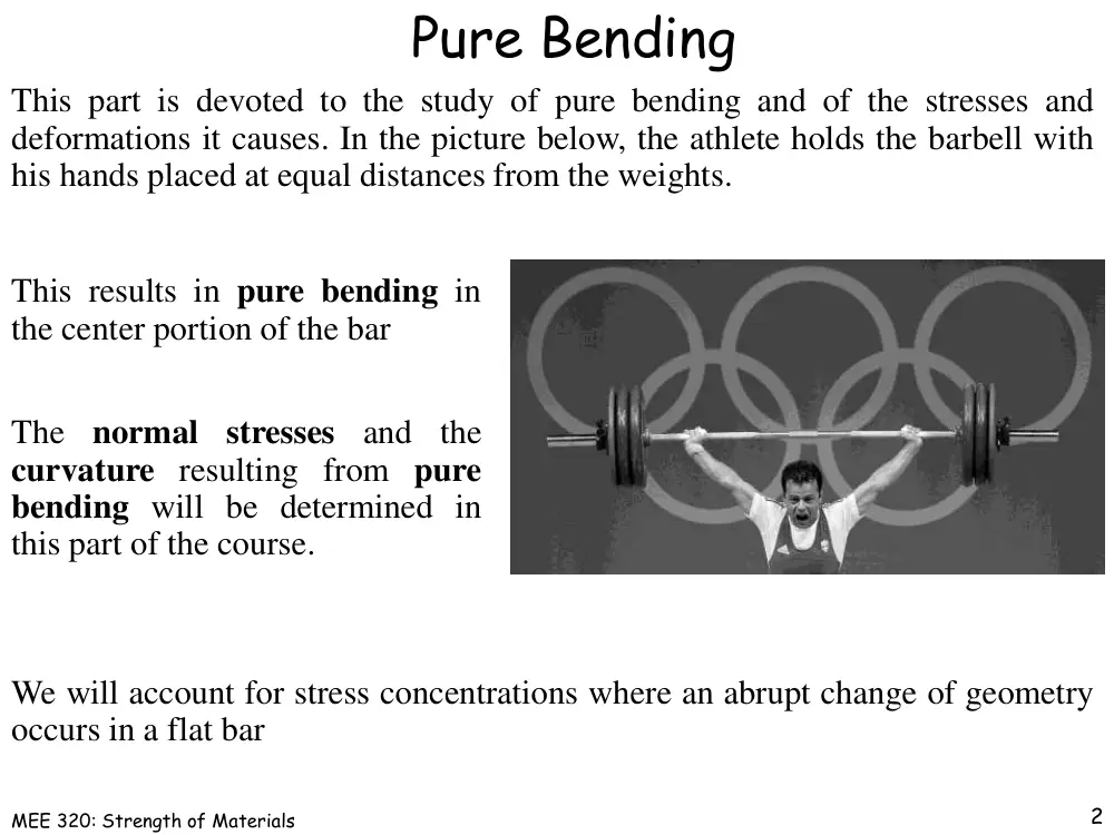
This part is devoted to the study of pure bending and of the stresses and
deformations it causes. In the picture below, the athlete holds the barbell with
his hands placed at equal distances from the weights.
This results in pure bending in
the center portion of the bar
The
normal
stresses
and
the
curvature resulting from pure
bending will be determined in
this part of the course.
We will account for stress concentrations where an abrupt change of geometry
occurs in a flat bar
2
MEE 320: Strength of Materials
Pure Bending
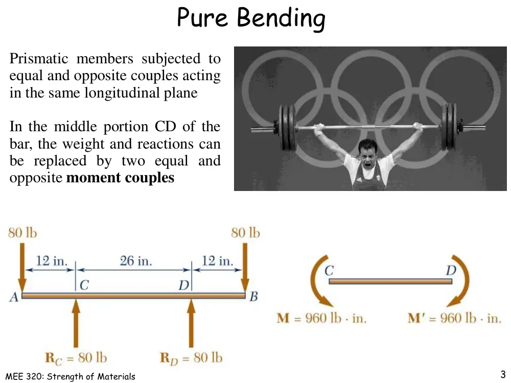
Prismatic members subjected to
equal and opposite couples acting
in the same longitudinal plane
In the middle portion CD of the
bar, the weight and reactions can
be replaced by two equal and
opposite moment couples
3
MEE 320: Strength of Materials
Bar Clamp
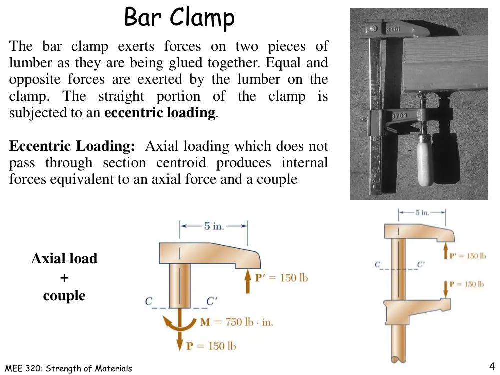
The bar clamp exerts forces on two pieces of
lumber as they are being glued together. Equal and
opposite forces are exerted by the lumber on the
clamp. The straight
portion of the clamp is
subjected to an eccentric loading.
Eccentric Loading: Axial loading which does not
pass through section centroid produces internal
forces equivalent to an axial force and a couple
4
Axial load
+
couple
MEE 320: Strength of Materials
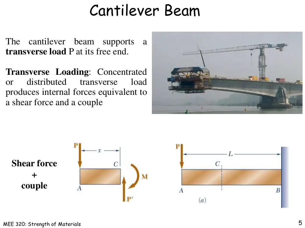
Cantilever Beam
The
cantilever
beam
supports
a
transverse load P at its free end.
Transverse Loading: Concentrated
or
distributed
transverse
load
produces internal forces equivalent to
a shear force and a couple
5
Shear force
+
couple
MEE 320: Strength of Materials
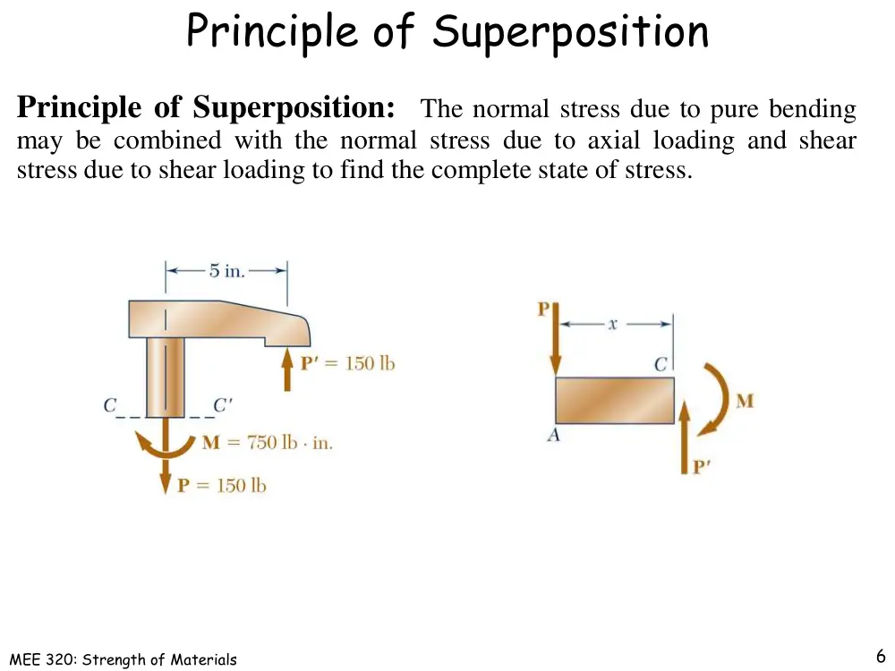
Principle of Superposition
Principle of Superposition:
The normal stress due to pure bending
may be combined with the normal stress due to axial loading and shear
stress due to shear loading to find the complete state of stress.
6
MEE 320: Strength of Materials
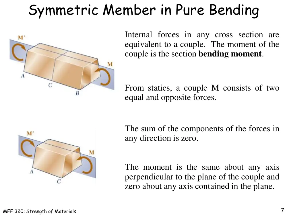
Symmetric Member in Pure Bending
From statics, a couple M consists of two
equal and opposite forces.
The sum of the components of the forces in
any direction is zero.
The moment is the same about any axis
perpendicular to the plane of the couple and
zero about any axis contained in the plane.
Internal forces in any cross section are
equivalent to a couple. The moment of the
couple is the section bending moment.
7
MEE 320: Strength of Materials
Symmetric Member in Pure Bending
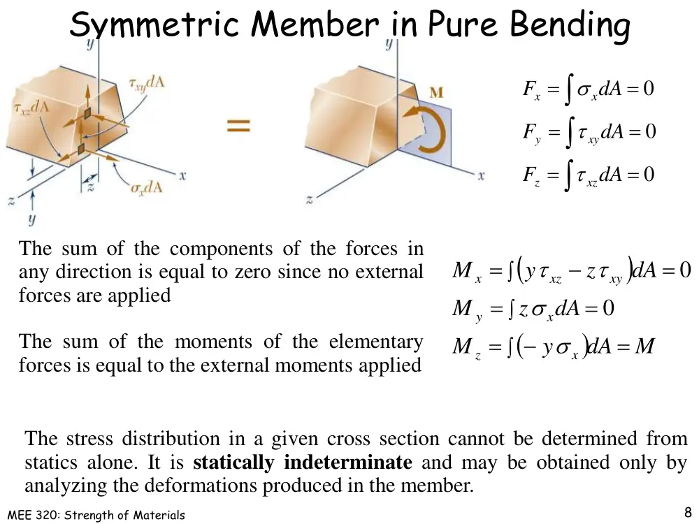
The sum of the components of the forces in
any direction is equal to zero since no external
forces are applied
8
The sum of the moments of the elementary
forces is equal to the external moments applied
The stress distribution in a given cross section cannot be determined from
statics alone. It is statically indeterminate and may be obtained only by
analyzing the deformations produced in the member.
0
0
0
dA
F
dA
F
dA
F
xz
z
xy
y
x
x
M
dA
y
M
dA
z
M
dA
z
y
M
x
z
x
y
xy
xz
x
0
0
MEE 320: Strength of Materials
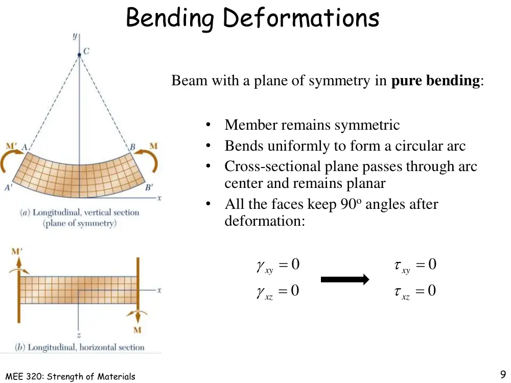
Bending Deformations
Beam with a plane of symmetry in pure bending:
9
0
0
xz
xy
0
0
xz
xy
•
Member remains symmetric
•
Bends uniformly to form a circular arc
•
Cross-sectional plane passes through arc
center and remains planar
•
All the faces keep 90o angles after
deformation:
MEE 320: Strength of Materials
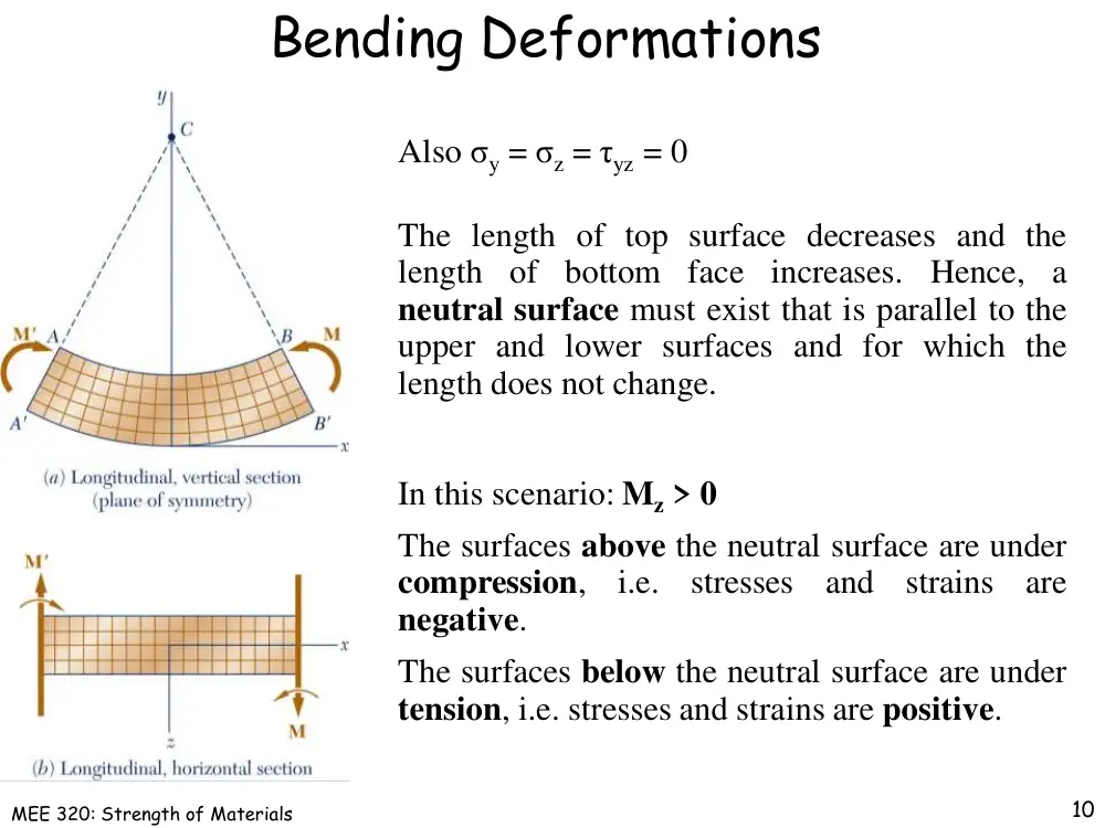
Bending Deformations
The length of top surface decreases and the
length of bottom face increases.
Hence, a
neutral surface must exist that is parallel to the
upper and lower surfaces and for which the
length does not change.
In this scenario: Mz > 0
The surfaces above the neutral surface are under
compression,
i.e.
stresses
and
strains
are
negative.
The surfaces below the neutral surface are under
tension, i.e. stresses and strains are positive.
10
Also σy = σz = τyz = 0
MEE 320: Strength of Materials
The strain at a distance y from E:
Initial length
Final length
Deformation
Strain
Max Strain
Strain Due to Bending
Neutral
axis:
Arc
DE
is
the
intersection of the neutral surface and the
plane of symmetry
y
L
11
y
y
L
x
L
y
y
L
L
c
m
m
x
c
y
MEE 320: Strength of Materials
Stress Due to Bending
For a linearly elastic material,
For equilibrium,
0
0
dA
c
y
dA
F
m
x
x
First moment with respect to neutral plane is zero.
Therefore, the neutral surface must pass through the section centroid.
m
x
m
x
x
c
y
c E
y
E
12
0
0
y
Ay
y dA
MEE 320: Strength of Materials
Stress Due to Bending
For static equilibrium,
S
M
I
Mc
c
I
y dA
c
M
dA
c
y
y
dA
y
M
m
m
m
m
x
2
13
m
x
c
y
I
My
x
S
M
I
Mc
m
I is the moment of inertia or second moment of the cross section
S is the elastic section modulus
c
I
S
y dA
I
2
MEE 320: Strength of Materials
Beam Section Properties
The maximum normal stress due to bending,
S
M
I
Mc
m
A
beam
section
with
a
larger
section
modulus will have a lower maximum stress.
Consider a rectangular beam cross section,
Ah
bh
h
bh
c
I
S
6
1
2
6
1
3
12
1
2
Between two beams with the same cross
sectional area, the beam with the greater depth
will be more effective in resisting bending.
Structural steel beams are designed to have a
large section modulus
14
MEE 320: Strength of Materials
Deformation Due to Bending
The deformation of the member by the
bending moment M is measured by the
curvature of the neutral surface
c
m
1
15
I
Mc
E
m
m
m
I
Mc
Ec
Ec
m
1
1
EI
M
1
MEE 320: Strength of Materials
Deformations: Transverse Cross-Section
Deformation due to bending moment M is quantified
by the curvature of the neutral surface
EI
M
1
Although cross sectional planes remain planar when
subjected to bending moments, in-plane deformations
are nonzero,
y
y
x
z
x
y
Expansion above the neutral surface and contraction
below it cause an in-plane curvature. The curvature of
the transverse cross section is called anticlastic
curvature
1
16
MEE 320: Strength of Materials
Example 1
17
4-1: Knowing that the couple shown acts in a vertical plane, determine the
stress at (a) point A, (b) point B.
MEE 320: Strength of Materials
Example 1
18
MEE 320: Strength of Materials
Example 2
19
4-11: Two vertical forces are applied to a
beam of the cross section shown. Determine
the
maximum
tensile
and
compressive
stresses in portion BC of the beam.
MEE 320: Strength of Materials
Example 2
20
MEE 320: Strength of Materials
Example 3
21
4-19: Knowing that for the extruded beam
shown the allowable stress is 120 MPa in
tension and 150 MPa in compression, determine
the largest couple M that can be applied.
MEE 320: Strength of Materials
Example 3
22
MEE 320: Strength of Materials
Example 4
23
4-24: A 60 N.m couple is applied to the steel bar shown. (a) Assuming that
the couple is applied about the z axis as shown, determine the maximum stress
and the radius of curvature of the bar. (b) Solve part a, assuming that the
couple is applied about the y axis. Use E = 200 GPa.
MEE 320: Strength of Materials
Example 4
24
MEE 320: Strength of Materials
Example 5
25
4-31:
A W200 × 31.3 rolled-steel beam is
subjected to a couple M of moment 45 kN.m.
Knowing that E = 200 GPa and v = 0.29,
determine (a) the radius of curvature ρ, (b) the
radius of curvature ρ’ of a transverse cross section.
MEE 320: Strength of Materials
Members Made of Several Materials
y
x
Consider a composite beam formed from two materials
with E1 and E2. The normal strain still varies linearly
with the distance y from the neutral axis. The stress in
material 1 will be different than that in material 2.
26
Normal Strain
Normal Stress
E y
E
E y
E
x
x
2
2
2
1
1
1
MEE 320: Strength of Materials
Members Made of Several Materials
The neutral axis does not pass through the
section centroid of the composite section.
27
Strain
Stress
MEE 320: Strength of Materials
Members Made of Several Materials
Static Equilibrium: The total normal force F resulting from the
stress distribution normal to the cross section should equal to zero:
28
1
1
1
1
1
A
A
E y dA
dA
F
0
2
1
F
F
F
The total force F1 exerted on the cross
sectional area A1 of material 1 is:
The total force F2 exerted on the cross
sectional area A2 of material 2 is:
2
2
2
2
2
A
A
E y dA
dA
F
MEE 320: Strength of Materials
Members Made of Several Materials
1
2
E
E
n
29
This equation can be easily solved as
follows: First let
The location of the neutral surface is found
from the static equilibrium equation:
0
2
1
2
1
A
A
E y dA
E y dA
F
0
)
(
0
2
1
2
1
1
1
1
1
A
A
A
A
E y ndA
E y dA
F
nE y dA
E y dA
F
If you now multiply the dimension of
A2 parallel to the neutral surface by n,
the force equation can be rewritten as:
0
'
1
1
2
1
A
A
E y dA
E y dA
F
MEE 320: Strength of Materials
Members Made of Several Materials
30
Then the equation is simplified to:
The integral of F depends now on E1 only. Physically, it defines the summation
of the normal forces resulting from the application of the normal stresses on A’
made of material 1. As if you converted the cross-section A2 made of material
2 to another cross-section A2’ made of material 1.
0
'
1
A
E y dA
F
The new converted cross section is:
'
'
2
1
A
A
A
Since it is essential for the distance y of each element from the neutral axis to
remain the same, the dimension parallel the neutral axis should change to n×b.
MEE 320: Strength of Materials
Members Made of Several Materials
I
My
x
31
The stress σx at any point of the
transformed member is obtained as
x
1
The stress σ1 at any point in material 1 of
the original member is obtained as follows,
nx
2
The neutral surface of the cross section A is simply
the centroid of the new converted cross section A’
The stress σ2 at any point in material 2 of the original member is calculated as:
Original
Area
Force
Transformed
n×Area
Force
MEE 320: Strength of Materials
Members Made of Several Materials
The deformation of a composite member is
determined using the transformed section as
E I
M
1
1
32
E1 is the Young’s modulus of material 1
I is the moment of inertia of the transformed section with respect to its
neutral axis
MEE 320: Strength of Materials
Reinforced Concrete Beams
Concrete beams subjected to bending moments are reinforced by
steel rods. The steel rods carry the entire tensile load below the
neutral surface. The upper part of the concrete beam carries the
compressive load only since concrete is weak in tension.
To determine the location of the neutral axis,
0
0
2
2
2
1
n A d
n A x
x
b
x
n A d
x
bx
s
s
s
In the transformed section, the cross sectional area of the steel,
As, is replaced by the equivalent area nAs where n = Es/Ec.
The normal stress in the concrete and steel
x
s
x
n
I
My
33
MEE 320: Strength of Materials
Stress Concentrations
Stress concentrations may occur in the vicinity of :
•
points where the loads are applied
•
abrupt changes in cross section
I
m K Mc
34
MEE 320: Strength of Materials
Example 6
35
4-33: A bar having the cross section shown
has been formed by securely bonding brass
and aluminum stock. Using the data given
below, determine the largest permissible
bending moment when the composite bar is
bent about a horizontal axis
MEE 320: Strength of Materials
Example 6
36
MEE 320: Strength of Materials
Example 7
37
4-40: A copper strip (Ec = 105 GPa) and an
aluminum strip (Ea = 75 GPa) are bonded
together to form the composite beam shown.
Knowing that the beam is bent about a
horizontal axis by a couple of moment M = 35
N.m, determine the maximum stress in (a) the
aluminum strip, (b) the copper strip.
MEE 320: Strength of Materials
Example 7
38
MEE 320: Strength of Materials
Example 8
39
4-52: A concrete beam is reinforced by three steel rods placed as shown. The
modulus of elasticity is 20 GPa for the concrete and 200 GPa for the steel.
Using an allowable stress of 9 MPa for the concrete and 140 MPa for the steel,
determine the largest allowable positive bending moment in the beam.
MEE 320: Strength of Materials
Example 8
40
MEE 320: Strength of Materials
Example 9
41
4-59: The rectangular beam shown is made of a plastic for which the value
of the modulus of elasticity in tension is one-half of its value in compression.
For a bending moment M = 600 N.m, determine the maximum (a) tensile
stress, (b) compressive stress.
MEE 320: Strength of Materials
Example 9
42
MEE 320: Strength of Materials
Example 10
43
4-65: A couple of moment M = 2 kN.m is to be applied to the end of a steel
bar. Determine the maximum stress in the bar (a) if the bar is designed with
grooves having semicircular portions of radius r = 10 mm, as shown in Fig. a,
(b) if the bar is redesigned by removing the material to the left and right of
the dashed lines as shown in Fig. b.
MEE 320: Strength of Materials
Example 10
44