
MEN 321 Problems For Chapter 4 with Solution, Fall 2009
Notre Dame University–Louaize · Fluid Mechanics II · 59 pages · with solution

Showing the first 10 of 59 pages. Download the PDF to see all of it.
More MEN 321 files
- Problems For Chapter 11 with Solution · Fall 2009Chapter · with solutionView
- Problems For Chapter 12 with Solution · Fall 2009Chapter · with solutionView
- Problems For Chapter 6 with Solution · Fall 2009Chapter · with solutionView
- Problems For Chapter 8 with Solution · Fall 2009Chapter · with solutionView
- Problems For Chapter 9 with Solution · Fall 2009Chapter · with solutionView
- Exam 1 · Fall 2015ExamView
Show the text of this chapter
| 41]
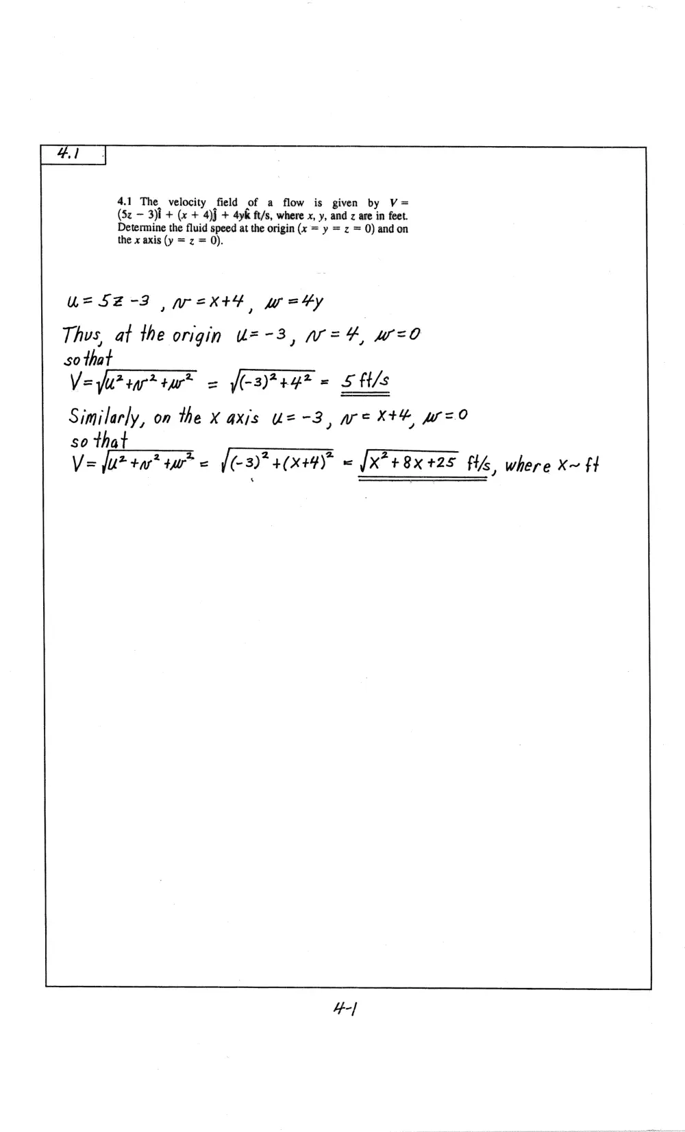
4.1 The velocity field of a flow is given by V=
(5z — 3)i + (x + 4)j + 4yk ft/s, where x, y, and z are in feet.
Determine the fluid speed at the origin (x = y = z = 0) andon
the x axis (y = z = 0).
A= 52-3 ,pext?, warty
Thus, at the origin U=-3, W=4, w=0
so that
V= Yu? sar? +ur* = (-3)7+47 = 5 ft/s
Similarly, on the X axis “= -3,eKxXth w=0
so that
Vz fut tart tw = {(-3)* 40x44) = [X74 8xX 425 FG where X~ 1
4-/
4.2.
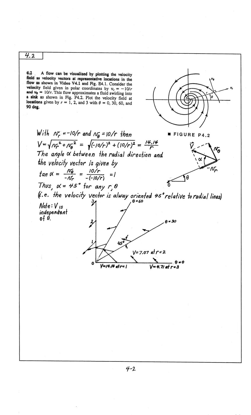
4,2 A flow can be visualized by plotting the velocity
field as velocity vectors at representative locations in the
flow as shown in Video V4.1 and Fig. E4.1. Consider the
velocity field given in polar coordinates by uv, = —10/r
and vp = 10/r. This flow approximates a fluid swirling into
a sink as shown in Fig. P4,2. Plot the velocity field at
locations given by r = 1, 2, and 3 with 6 = 0, 30, 60, and
90 deg,
With wz =-10/r and wg =10/r then
Ve agteng? = fei/p) + (ior = 4
The angle & between the radial direction and
the velocity vector is given by
~~ VM _ 10/r
tan = cae * Zire =!
Thus, K= ¥5° for any r,8
¢.e. the velocity vector is alway oriented #8°relative to radial lines)
3 =60
Note: V is
independent
of 8. 6 =320
O=0
Vei4. atre | Ve4Hatr<3
¥,3
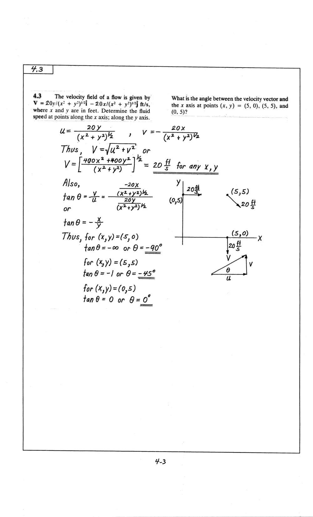
* 3 The velocity | field of a flow is given by
What is the angle between the velocity vector and
= 20y/(x? + yi — 20x/(x? + y2)7F ft/s,
the x axis at points (x, y) = (5, 0), (5, 5), and
Vhere x and y are in feet. Determine the fluid (0, 5)?
speed at points along the x axis; along the y axis. —_
2 : 20x
u= —20Y
(x24 3%? ai
Thus , V =u +y
4 2 +400
y= [ser I sof be yy
Also, -20X y
tan 0 =) = aan ee (0,5) a8 Ne
or ay , 20f
tan @ = - +
Thus, for (x,y) =(5, 0) 6,0)
tanO@=-00 or 8 =-90° 205
tan 6 =~] or @=- 45°
tor (X,y)=(0,5)
tan0= 0 or O= 0°
4
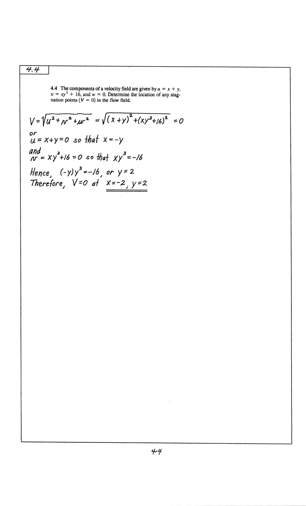
4.4 The components of a velocity field are given by u = x + y,
v = xy? + 16, and w = 0, Determine the location of any stag-
nation points (V = 0) in the flow field.
V=furt a? tur? = (x+y) +(xy34/6)*
Ve X+y=0 s0 that X=-y
and Xy'+l6 =O so that xy =-/6b
Hence, (-y)y’=-/6, or y=2
Therefore, V=O af X=-2, y=2
bY
45
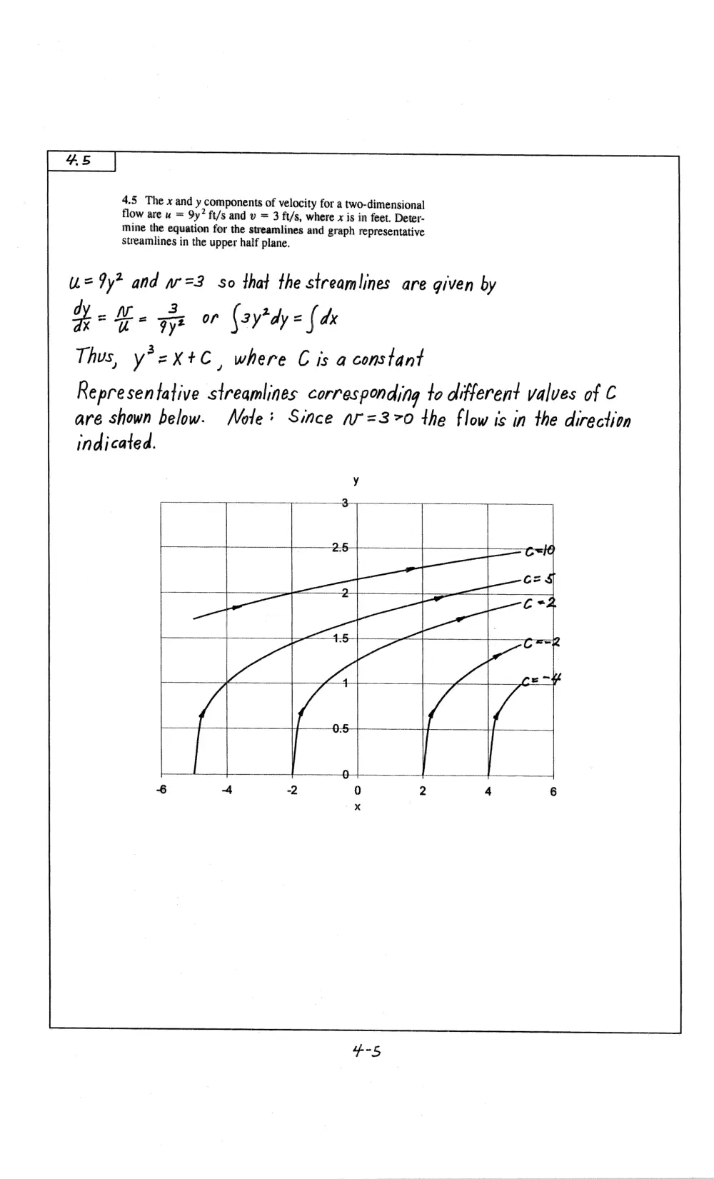
4.5 The x and y components of velocity for a two-dimensional
flow are u = 9y? ft/s and v = 3 ft/s, where x is in feet. Deter-
mine the equation for the streamlines and graph representative
Streamlines in the upper half plane.
u=%y? and w=3 so that the streamlines are given by
d 3 2
He He Tye (ay*dy = { dx
Thus, y*2Xx+C, where C is a constant
Representative streamlines corresponding to different valves of C
are shown below. WNole+ Since nr=370 the flow is in the direction
indicated.
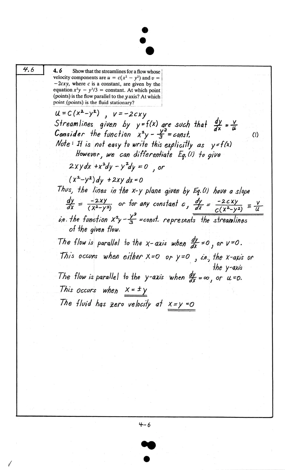
4.6 Show that the streamlines for a flow whose |
velocity components are u = c(x? — y*) andv = |
—2cxy, where c is a constant, are given by the!
equation xy — y*/3 = constant. At which point |
(points) is the flow parallel to the y axis? At which |
point (points) is the fluid stationary?
U=C(x*-y*) | y=-2exy
Streamlines given by y=f(x) are such that dy +
Consider the function x*y- ¥ =const, ()
Note* If is not easy to write this explicitly as y=t(x)
However, we can ditterentiate Ey, (/) to give
2xydx +x*dy - y"dy =O | or
(x*-y*) dy +2xy dk=0
Thus, the lines in the x-y plane given by Fy.U) have a slope
dy _ -2xy dy _ -2cxy _ y
H = Gays for any constant c, > a Wey et
de. the function x*y -¥ =const. represents the streanlines
of the given flow.
The flow is parallel to the x-axis when 4 20 ,r ved.
This occurs when either X=0 or y=O , ge, the X-axis or
the y-axis
or U=0.
The flow is paralle| to the y-axis when W «09
This occurs when X=+y
/
The flvid has zero velcty at x=y <O
47
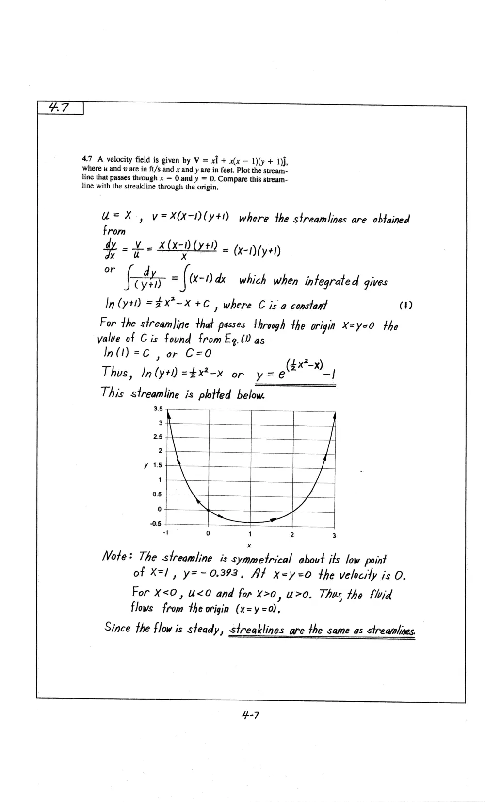
4.7 A velocity field is given by V = xi + x(x — 1)(y + 1)j,
where u and v are in ft/s and x and y are in feet. Plot the stream-
line that passes through x = Q and y = 0. Compare this stream-
line with the streakline through the origin,
“=X , v=X(x-I) (yt!) where the streamlines are obtained
from
ty = te A(x-D (y+) = (x-I)(y+l)
°r (tty = (tn dx which when integrated gives
In (yt) =2X°-X + | where C is a constant (1)
For the streamline that passes throogh the origin X=y<0 the
valve of Cis found from Eg. () as
In(I)=C , or C=O
AL ye
Thos, In (yt) =$x*-x or y= x)
|
This streamline is plotted below.
“sh T -
==
1, \ | [|
os VA
-1 0 1 2 3
Note+ The streamline is symmetrical about its low point
of X=/, y=- 0.393, At x=y=0 the velocity is O.
For X<O, u<0 and for X>0, u>0, Thos the thid
flows from the origin (x=y=0),
Since the flow is steady, streaklines are the same as streamlines.
4-7
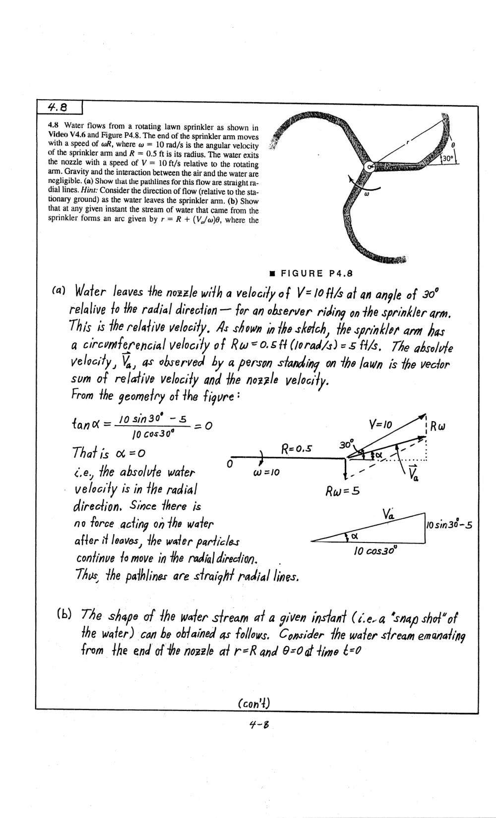
4.8 Water flows from a rotating lawn Sprinkler as shown in
Video V4.6 and Figure P4.8. The end of the sprinkler arm moves
with a speed of wR, where w = 10 rad/s is the angular velocity
of the sprinkler arm and R = 0.5 ft is its radius, The water exits
the nozzle with a speed of V = 10 ft/s relative to the rotating
arm. Gravity and the interaction between the air and the water are
negligible. (a) Show that the pathlines for this flow are Straight ra-
dial lines. Hint: Consider the direction of flow (relative to the sta-
tionary ground) as the water leaves the sprinkler arm. (b) Show
that at any given instant the stream of water that came from the
sprinkler forms an arc given by r = R + (V,/w)0, where the
m FIGURE P4.8
(a) Water leaves the nozzle with a velocity of V=l0ft4 al an angle of 30°
relalive to the radial direction — for an observer riding on the sprinkler arm,
This is the relative velocity, As shown in the sketch ), the sprinkler arm has
qa circumterencial velocity of Rw=o.s# (lorad/s)=5 ft/s, The absolvfe
Velocity, Vy, as observed by a person standing on the lawn is the vector
sum of relative velocity and the nozzle velocity,
From the geometry of the figure:
n3o -5
an ]0 cos30°
That is & =O
ce, the absolvte water
- velocity is in the radial
direction, Since there is
Va -_
no force acting on the water wis
after it leaves, the water particles *
i] oO
continve to move in the radial direction, — 9 0830
Thus, the pathlines are straight radial lines.
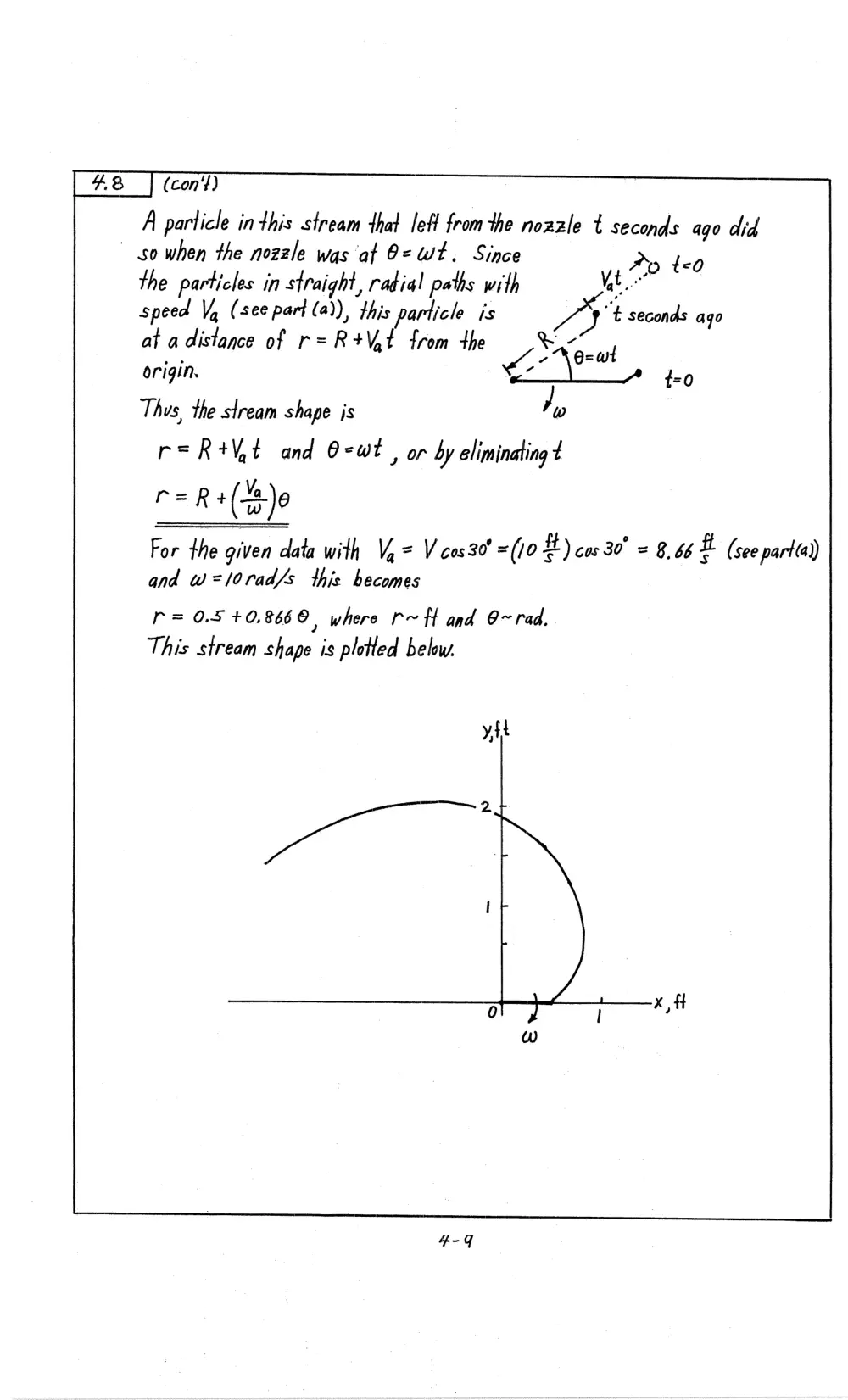
(b) The shape of the water stream at a given instant (¢.e-4 ‘snap shot” of
the water) can be obtained gs follows, Consider the water stream emanating
from the end of the nozzle at r=R and 9=0at time &=0
(con't)
A particle inthis stream that left fromthe nozzle t seconds ago did
so when the nozzle was af O= Wt. Since Ay to
the particles in straight, radial paths with Nat
speed Va (see part (a)), this particle is YY “t seconds ago
at a distance of r=R+VAt from +he : “6
origin.
Thus, the stream shape js J w
r=R+Vit and O-wt , or by eliminating t
r=R+ (B)e
For the given data with V,= Vcos30’ =(/0 #) cus. 30° = 846 i (see partia))
and w=/orad/s this becomes
r= 0.5 +0,8660, where r~tt and O~ rad.
This stream shape is plotted below.
*4.9 |
a Consider a ball thrown with initial speed V, at an angle
of @ as shown in Fig. P4.9a. As discussed in beginning physics,
if friction is negligible the path that the ball takes is given by
y = (tan 6)x — [g/(2 Vo?cos? 6) ]x?
That is, y = cyx + cox?, where c, and C2 are constants. The path
is a parabola. The pathline for a stream of water leaving a small
nozzle is shown in Fig. P4.9b and Video V4.3. The coordinates ‘1.25 —0.20 y (a)
for this water stream are given in the following table. (a) Use _1.50 —0.53
the given data to determine appropriate values for c, andc,in 1.75 —0.90
the above equation and, thus, show that these water particles 2.00 ~ 1.43
also follow a parabolic pathline. (b) Use your values of c, and
C2 to determine the speed of the water, Vo, leaving the nozzle.
(b)
An EXCEL Program was used to plof the X-y data and
to fit a second order curve to the data. The results are shown below.
y vs x for Water Stream
y, ft
y = -8.4987x" + 0.71 15x
-0.1 _ _
0 0.05 0.1 0.15 0.2
x, ft
Ths, with Y=GX+G,x> if follows that
C,= 0.75 = fan@ or @ = 35,4"
and |
C, = 8.4997 = - —
2\,? cas*O
or :
2 32,2 Ft
r " = 8S 2
Yo ZUEHN) co* as) = 7-855
Thus, V,= 1.69
'
M@ FIGURE P4.9
4-10