
CIVE 310 Exam 2, Fall 2004
American University of Beirut · Mechanics of Materials · 12 pages



Showing the first 10 of 12 pages. Download the PDF to see all of it.
More CIVE 310 files
- Exam 1 · Fall 2016ExamView
- Exam 1 All Exam 1 Previouses · Fall 2015ExamView
- Exam 1 Previouses (Zip File) · Fall 2015ExamView
- Exam 3 Previouses Zip File (No Solution) · Fall 2015Exam · with solutionView
- Exam 2 Quiz 2 Previouses Zip File (No Solution) · Fall 2015Exam · with solutionView
- Exam 1 · Spring 2013ExamView
- Exam 1 · Fall 2012ExamView
- Exam 1 · Spring 2011ExamView
Show the text of this exam
CIVE310 - Fall 2004-2005
Quiz 2
H. Basha &M. Mabsout
1
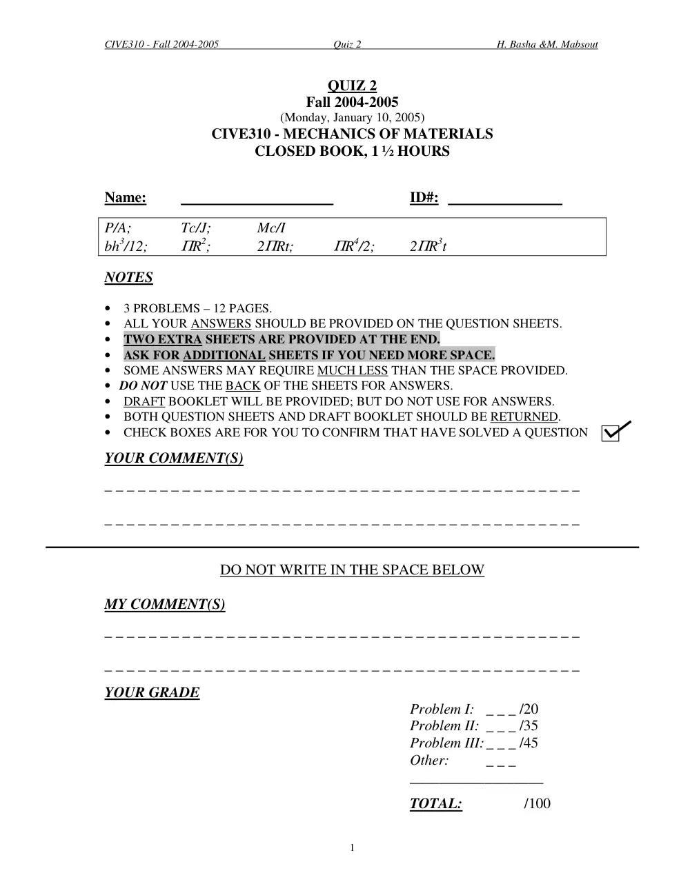
QUIZ 2
Fall 2004-2005
(Monday, January 10, 2005)
CIVE310 - MECHANICS OF MATERIALS
CLOSED BOOK, 1 ½ HOURS
Name:
ID#:
P/A;
Tc/J;
Mc/I
bh3/12;
ΠR2;
2ΠRt;
ΠR4/2;
2ΠR3t
NOTES
• 3 PROBLEMS – 12 PAGES.
• ALL YOUR ANSWERS SHOULD BE PROVIDED ON THE QUESTION SHEETS.
• TWO EXTRA SHEETS ARE PROVIDED AT THE END.
• ASK FOR ADDITIONAL SHEETS IF YOU NEED MORE SPACE.
• SOME ANSWERS MAY REQUIRE MUCH LESS THAN THE SPACE PROVIDED.
• DO NOT USE THE BACK OF THE SHEETS FOR ANSWERS.
• DRAFT BOOKLET WILL BE PROVIDED; BUT DO NOT USE FOR ANSWERS.
• BOTH QUESTION SHEETS AND DRAFT BOOKLET SHOULD BE RETURNED.
• CHECK BOXES ARE FOR YOU TO CONFIRM THAT HAVE SOLVED A QUESTION
YOUR COMMENT(S)
_ _ _ _ _ _ _ _ _ _ _ _ _ _ _ _ _ _ _ _ _ _ _ _ _ _ _ _ _ _ _ _ _ _ _ _ _ _ _ _ _ _ _
_ _ _ _ _ _ _ _ _ _ _ _ _ _ _ _ _ _ _ _ _ _ _ _ _ _ _ _ _ _ _ _ _ _ _ _ _ _ _ _ _ _ _
DO NOT WRITE IN THE SPACE BELOW
MY COMMENT(S)
_ _ _ _ _ _ _ _ _ _ _ _ _ _ _ _ _ _ _ _ _ _ _ _ _ _ _ _ _ _ _ _ _ _ _ _ _ _ _ _ _ _ _
_ _ _ _ _ _ _ _ _ _ _ _ _ _ _ _ _ _ _ _ _ _ _ _ _ _ _ _ _ _ _ _ _ _ _ _ _ _ _ _ _ _ _
YOUR GRADE
Problem I: _ _ _ /20
Problem II: _ _ _ /35
Problem III: _ _ _ /45
Other:
_ _ _
__________________
TOTAL:
/100
CIVE310 - Fall 2004-2005
Quiz 2
H. Basha &M. Mabsout
2
Problem I: (20 points)
The block shown in Figure I is made of a magnesium alloy for which the modulus of elasticity
E= 50,000 MPa (N/mm2) and Poisson’s ratio ν= 1/3. Assume linear elastic behavior, and given
that σX= 180 MPa in compression, determine the following:
1. The magnitude of σY for which the change in height LY of the block is zero. (5 points)
2. The corresponding change in the horizontal area (XZ Plane). (7 points)
3. The corresponding change in volume using 2 different methods and compare. (8 points)
Calculations and/or Diagrams:
LX = 100 mm
LY = 40 mm
LZ = 25 mm
Y
Z
σY
σX
Figure I
X
CIVE310 - Fall 2004-2005
Quiz 2
H. Basha &M. Mabsout
3
Calculations and/or Diagrams (cont’d):
CIVE310 - Fall 2004-2005
Quiz 2
H. Basha &M. Mabsout
4
Problem II: (35 points)
The weightless shaft shown in Figure II is made of a thick tube. Assuming linear elastic
behavior, and given that the allowable shear stress τall is 70,000 kPa (kN/m2) and shear modulus
G is 200x106 kPa (kN/m2), determine:
1. The maximum torque T which can be applied, and plot the shear stress distribution on the
cross section. Calculate the torsional stiffness and the rotation at the free end. (13 points)
2. The maximum torque which can be applied on a solid shaft of same weight and material
(i.e. same cost). Compare with question 1 and briefly discuss. (10 points)
3. The diameter and cross-section area of a thin shaft of thickness t=1 cm which will result
in the same torque capacity as the thick shaft in Figure II; compare cost and briefly
discuss. (12 points)
Calculations and/or Diagrams:
Din = 10 cm
Figure II
Dout = 15 cm
T
L = 2 m
CIVE310 - Fall 2004-2005
Quiz 2
H. Basha &M. Mabsout
5
Calculations and/or Diagrams (cont’d):
CIVE310 - Fall 2004-2005
Quiz 2
H. Basha &M. Mabsout
6
Calculations and/or Diagrams (cont’d):
CIVE310 - Fall 2004-2005
Quiz 2
H. Basha &M. Mabsout
7
Problem III: (45 points)
A steel I-beam with overhanging ends is subjected to a uniformly distributed load w, as shown in
Figure III. The dimensions of the beam are shown on the cross-section. The yield stress in
tension and compression is σYT = σYC = 200 MPa (N/mm2) and the factor of safety assumed is 1.6.
1. Draw the shear and bending moment diagram of the beam. (10 points)
2. Determine the axial flexural stresses at the critical sections of maximum negative and
positive moments, and briefly discuss safety. (10 points)
3. Compute the moment capacity of the section in tension and compression, and determine
the maximum additional allowable uniform load ∆w that can be added to the beam safely.
(15 points)
4. Compute the maximum permissible concentrated load applied at mid length of the beam
(between B and C), in addition to the existing w (without ∆w). (10 points)
Calculations and/or Diagrams:
10
2 m
2 m
B
A
5 m
C
Figure III
w =30 kN/m
D
20
200
20
150
Cross-Section
(mm)
CIVE310 - Fall 2004-2005
Quiz 2
H. Basha &M. Mabsout
8
Calculations and/or Diagrams (cont’d):
CIVE310 - Fall 2004-2005
Quiz 2
H. Basha &M. Mabsout
9
Calculations and/or Diagrams (cont’d):
CIVE310 - Fall 2004-2005
Quiz 2
H. Basha &M. Mabsout
10
Calculations and/or Diagrams (cont’d):
CIVE310 - Fall 2004-2005
Quiz 2
H. Basha &M. Mabsout
11
EXTRA SHEET 1: Continued from page _______
Name:
ID#:
Calculations and/or Diagrams:
CIVE310 - Fall 2004-2005
Quiz 2
H. Basha &M. Mabsout
12
EXTRA SHEET 2: Continued from page _______
Name:
ID#:
Calculations and/or Diagrams: