
EECE 310 Exam 1, Fall 2007
American University of Beirut · Electronics · 6 pages

More EECE 310 files
- Midterm · Fall 2014ExamView
- Midterm with Solutions · Fall 2014Exam · with solutionView
- Midterm · Fall 2013ExamView
- Midterm · Fall 2012ExamView
- Exam 2 with Answers · Fall 2011Exam · with solutionView
- Exam 1 with Answers · Fall 2011Exam · with solutionView
- Midterm with Solution · Summer 2011Exam · with solutionView
- Exam 1 · Fall 2010ExamView
Show the text of this exam
EECE 310 – Electronics – Quiz 1 – Fall 2007-2008 - Page 1 of 6
American University of Beirut
Department of Electrical and Computer Engineering
EECE 310 – Electronics
Quiz 1 – November 2, 2007
Closed Book – No Programmable Calculators
90 minutes
Penalty is 5 to 1
Name: _________________________________
ID number: _________________
Assume in the following that VT = 25 mV.
▬▬▬▬▬▬▬▬
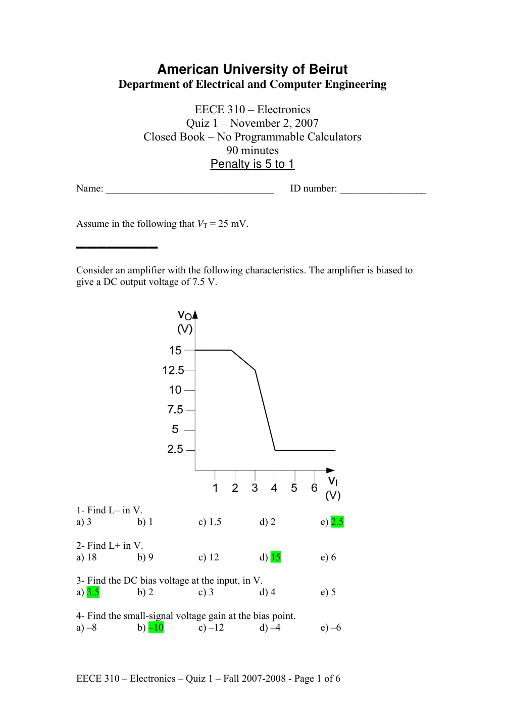
Consider an amplifier with the following characteristics. The amplifier is biased to
give a DC output voltage of 7.5 V.
1- Find L– in V.
a) 3
b) 1
c) 1.5
d) 2
e) 2.5
2- Find L+ in V.
a) 18
b) 9
c) 12
d) 15
e) 6
3- Find the DC bias voltage at the input, in V.
a) 3.5
b) 2
c) 3
d) 4
e) 5
4- Find the small-signal voltage gain at the bias point.
a) –8
b) –10
c) –12
d) –4
e) –6
EECE 310 – Electronics – Quiz 1 – Fall 2007-2008 - Page 2 of 6
5- What is the largest undistorted sinusoidal output signal, in V, that can be produced
(around the bias point)?
a) 2 sin(ωt)
b) 3 sin(ωt)
c) 4 sin(ωt)
d) 5 sin(ωt)
e) 6 sin(ωt)
▬▬▬▬▬▬▬▬
An amplifier uses +12 V and –12 V power supplies. The average current in each of
the two supplies is 10 mA. The amplifier provides a 3.0 V RMS sine wave to a 50 Ω
load when the input is a 0.5 V RMS sine wave, from which a 5 mA RMS sine wave
current is drawn.
6- Find the voltage gain of the amplifier in dB.
a) 13.6
b) 14.6
c) 15.6
d) 16.4
e) 12.5
7- Find the power gain of the amplifier in dB.
a) 19.4
b) 15.5
c) 16.6
d) 17.7
e) 18.6
8- Find the efficiency of the amplifier (in %).
a) 90
b) 75
c) 60.5
d) 36.5
e) 48
9- What is the power dissipated in the amplifier (in mW)?
a) 152
b) 125
c) 95
d) 61
e) 23
▬▬▬▬▬▬▬▬
Consider the circuit shown below.
Assume R1 = 10 Ω; R2 = 12 Ω; R3 = 30 Ω. The diode is a PN junction diode with n =
1.5. The diode current is 1 mA at the original value of VA. The source VA now
increases by a small amount va = 10 mV.
10- Find the change vy (in mV) in the value of VY.
a) 1.03
b) 1.73
c) 2.24
d) 2.63
e) 3.18
11- Find the change in diode current (in μA).
a) 53.0
b) 103
c) 86.6
d) 74.8
e) 65.7
▬▬▬▬▬▬▬▬
EECE 310 – Electronics – Quiz 1 – Fall 2007-2008 - Page 3 of 6
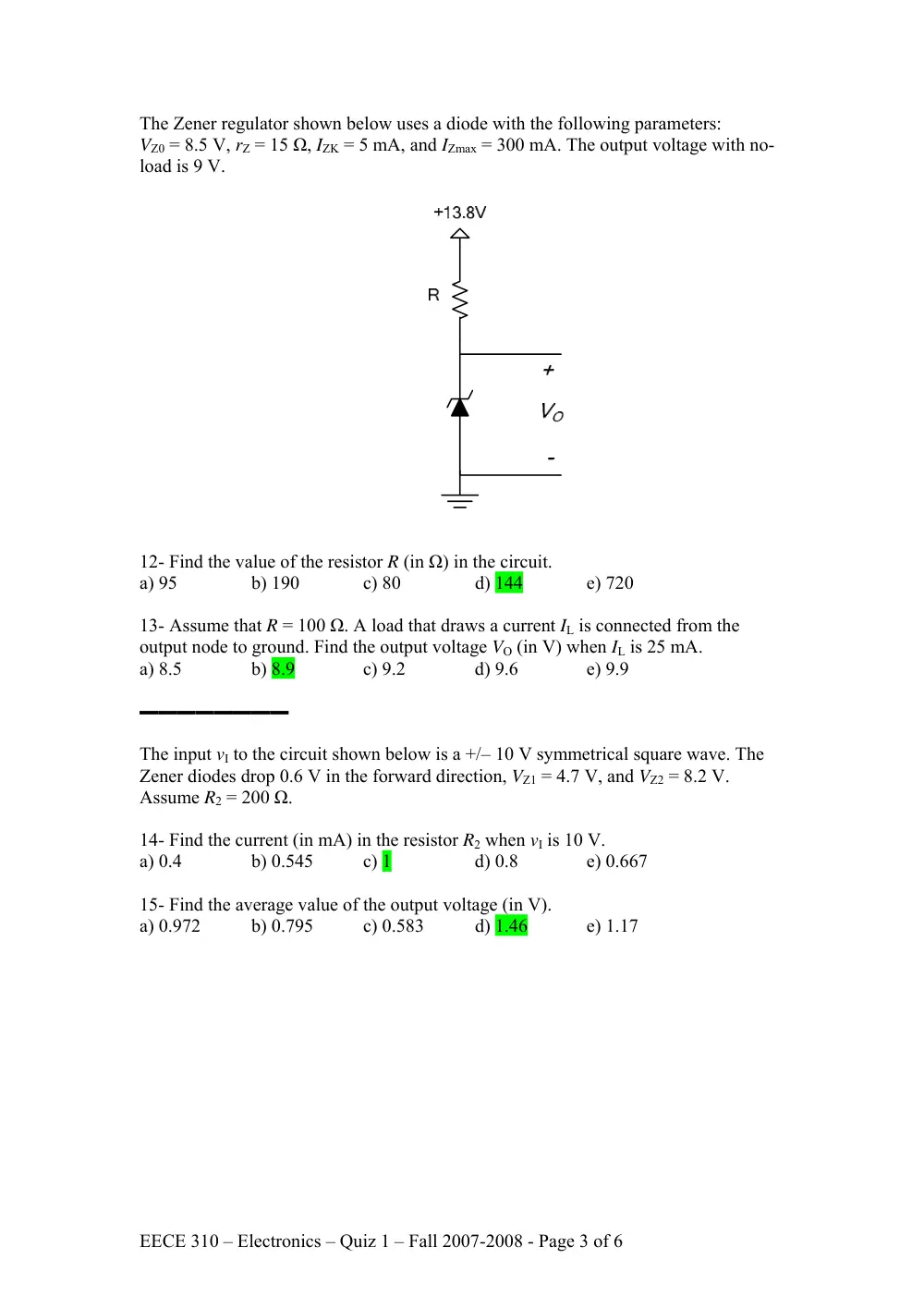
The Zener regulator shown below uses a diode with the following parameters:
VZ0 = 8.5 V, rZ = 15 Ω, IZK = 5 mA, and IZmax = 300 mA. The output voltage with no-
load is 9 V.
12- Find the value of the resistor R (in Ω) in the circuit.
a) 95
b) 190
c) 80
d) 144
e) 720
13- Assume that R = 100 Ω. A load that draws a current IL is connected from the
output node to ground. Find the output voltage VO (in V) when IL is 25 mA.
a) 8.5
b) 8.9
c) 9.2
d) 9.6
e) 9.9
▬▬▬▬▬▬▬▬
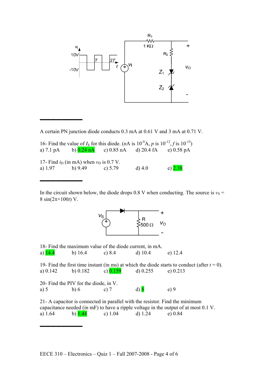
The input vI to the circuit shown below is a +/– 10 V symmetrical square wave. The
Zener diodes drop 0.6 V in the forward direction, VZ1 = 4.7 V, and VZ2 = 8.2 V.
Assume R2 = 200 Ω.
14- Find the current (in mA) in the resistor R2 when vI is 10 V.
a) 0.4
b) 0.545
c) 1
d) 0.8
e) 0.667
15- Find the average value of the output voltage (in V).
a) 0.972
b) 0.795
c) 0.583
d) 1.46
e) 1.17
EECE 310 – Electronics – Quiz 1 – Fall 2007-2008 - Page 4 of 6
▬▬▬▬▬▬▬▬
A certain PN junction diode conducts 0.3 mA at 0.61 V and 3 mA at 0.71 V.
16- Find the value of IS for this diode. (nA is 10-9A, p is 10-12, f is 10-15)
a) 7.1 pA
b) 0.24 nA
c) 0.85 nA
d) 20.4 fA
e) 0.58 pA
17- Find iD (in mA) when vD is 0.7 V.
a) 1.97
b) 9.49
c) 5.79
d) 4.0
e) 2.38
▬▬▬▬▬▬▬▬
In the circuit shown below, the diode drops 0.8 V when conducting. The source is vS =
8 sin(2π×100t) V.
18- Find the maximum value of the diode current, in mA.
a) 14.4
b) 16.4
c) 8.4
d) 10.4
e) 12.4
19- Find the first time instant (in ms) at which the diode starts to conduct (after t = 0).
a) 0.142
b) 0.182
c) 0.159
d) 0.255
e) 0.213
20- Find the PIV for the diode, in V.
a) 5
b) 6
c) 7
d) 8
e) 9
21- A capacitor is connected in parallel with the resistor. Find the minimum
capacitance needed (in mF) to have a ripple voltage in the output of at most 0.1 V.
a) 1.64
b) 1.44
c) 1.04
d) 1.24
e) 0.84
▬▬▬▬▬▬▬▬
EECE 310 – Electronics – Quiz 1 – Fall 2007-2008 - Page 5 of 6
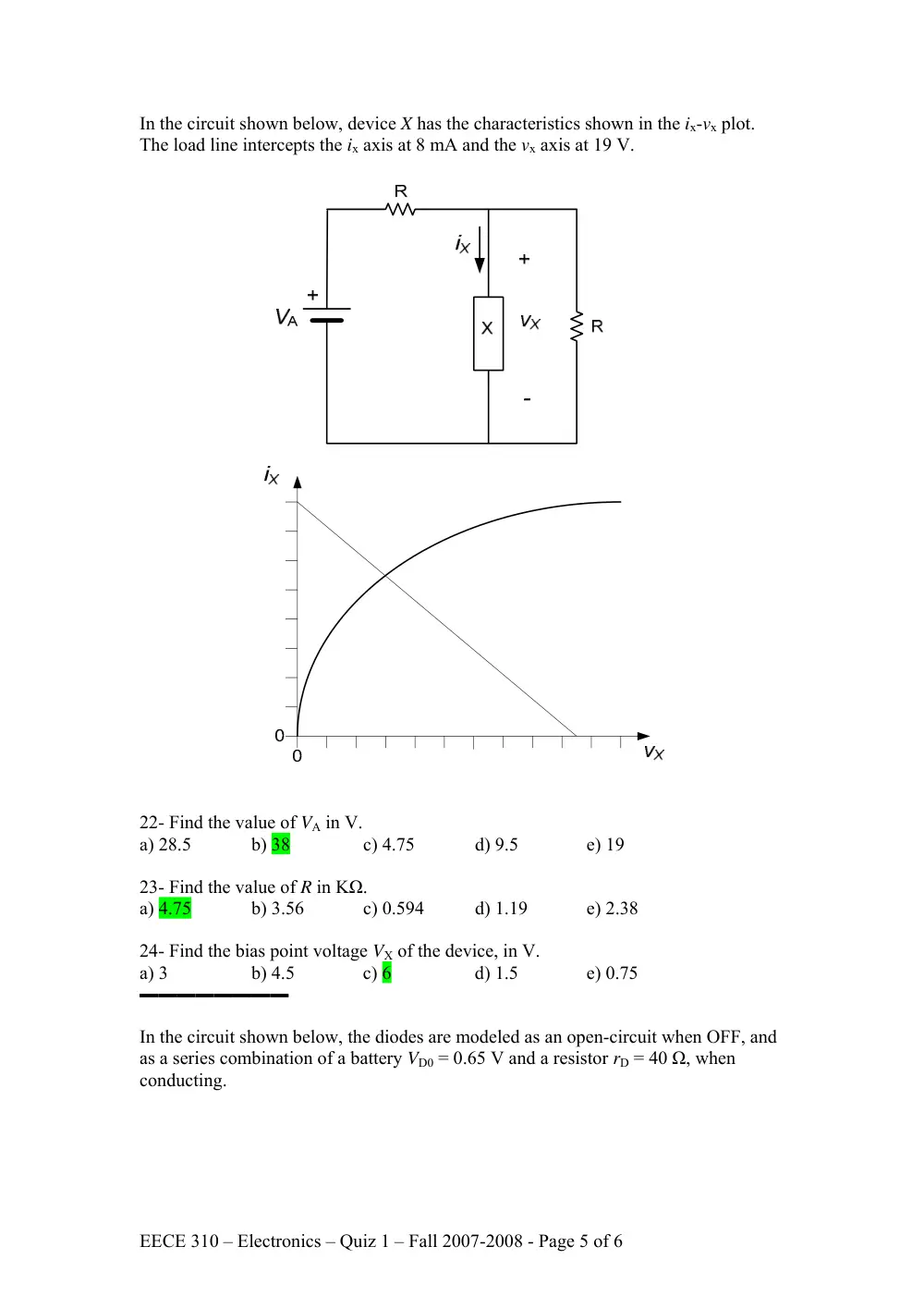
In the circuit shown below, device X has the characteristics shown in the ix-vx plot.
The load line intercepts the ix axis at 8 mA and the vx axis at 19 V.
22- Find the value of VA in V.
a) 28.5
b) 38
c) 4.75
d) 9.5
e) 19
23- Find the value of R in KΩ.
a) 4.75
b) 3.56
c) 0.594
d) 1.19
e) 2.38
24- Find the bias point voltage VX of the device, in V.
a) 3
b) 4.5
c) 6
d) 1.5
e) 0.75
▬▬▬▬▬▬▬▬
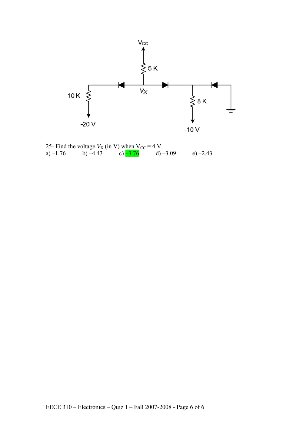
In the circuit shown below, the diodes are modeled as an open-circuit when OFF, and
as a series combination of a battery VD0 = 0.65 V and a resistor rD = 40 Ω, when
conducting.
EECE 310 – Electronics – Quiz 1 – Fall 2007-2008 - Page 6 of 6
25- Find the voltage VX (in V) when VCC = 4 V.
a) –1.76
b) –4.43
c) –3.76
d) –3.09
e) –2.43