
EECE 310 Midterm with Solution, Summer 2011
American University of Beirut · Electronics · 6 pages · Prof. Ali Chehab · with solution



More EECE 310 files
- Midterm with Solutions · Fall 2014Exam · with solutionView
- Midterm · Fall 2014ExamView
- Midterm · Fall 2013ExamView
- Midterm · Fall 2012ExamView
- Exam 2 with Answers · Fall 2011Exam · with solutionView
- Exam 1 with Answers · Fall 2011Exam · with solutionView
- Midterm · Summer 2010ExamView
- Exam 1 · Fall 2010ExamView
Show the text of this exam
EECE 310 – Midterm – Summer 2011
Page 1 of 6
American University of Beirut
Department of Electrical and Computer Engineering
EECE 310 – Electronics
Midterm – July 15, 2011
Closed Book – No Programmable Calculators
120 minutes
Profs. Chehab and Kayssi
Penalty is 5 to 1
(1 to 4 wrong answers do not result in a penalty; 5 to 9 wrong answers cancel one
correct answer; 10 to 14 wrong answers cancel two correct answers; and so on)
Name: _________________________________ ID number: _________________
Unless otherwise specified, assume that:
VT = 25 mV n = 1 ni = 1.5×1010 cm–3 q = 1.6×10⁻¹⁹ C
p
p
dp
J
= −qD dx
n
n
dn
J
= qD dx
(
)
d
p
n
J
qp
qn
E
μ
μ
=
+
I = J × A
0
2
ln
A
D
T
i
N N
V
V
n
⎛
⎞
=
⎜
⎟
⎝
⎠
EECE 310 – Midterm – Summer 2011
Page 2 of 6
1. The saturation levels at the output of an amplifier are +/– 12 V. To avoid saturation and obtain the
maximum undistorted output, a sinusoidal voltage with zero average and an RMS value of 0.4 V is
used at the input. Find the voltage gain (in V/V) of this amplifier.
a) 42.4
b) 33.9
c) 28.3
d) 24.2
e) 21.2
2. An amplifier produces a 1.1 V peak-to-peak output voltage across a 30 Ω load resistor. Find the
power gain of the amplifier (in dB) if the input power is 1 mW.
a) 11.8
b) 9.7
c) 7.0
d) 10.8
e) 8.5
3. The efficiency of an amplifier powered from a 9 V battery is 35%. The power delivered at the
output is 0.2 W. Find the average current (in mA) drawn from the battery.
a) 49.4
b) 88.9
c) 63.5
d) 74.1
e) 55.6
4. A circuit consists of a series connection of a 9 V battery, a 15 kΩ resistor, and a forward-biased
diode. The diode has IS = 10–16 A and n = 1. Starting with an initial guess for the diode current equal to
the current that flows if the diode were ideal, find the value of the diode current (in mA) using
iterations.
a) 0.307
b) 0.251
c) 0.459
d) 0.376
e) 0.551
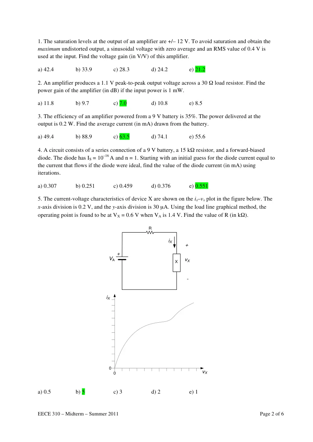
5. The current-voltage characteristics of device X are shown on the ix–vx plot in the figure below. The
x-axis division is 0.2 V, and the y-axis division is 30 μA. Using the load line graphical method, the
operating point is found to be at VX = 0.6 V when VA is 1.4 V. Find the value of R (in kΩ).
+
+
-
vX
VA
R
iX
vX
iX
0
0
X
�
a) 0.5
b) 5
c) 3
d) 2
e) 1
EECE 310 – Midterm – Summer 2011
Page 3 of 6
6. A diode is modeled by VD0 = X Volts and rD = Y Ohms when conducting, and an open-circuit
when OFF. The diode voltage increases from 0.72 V to 0.8 V when the diode current increases
from 1 mA to 10 mA. Find X (in V).
a) 0.756
b) 0.733
c) 0.689
d) 0.711
e) 0.667
7. In the previous problem, find Y (in Ω).
a) 6.67
b) 4.44
c) 13.3
d) 11.1
e) 8.89
8. A piece of semiconductor material is doped with acceptor atoms with a density NA = 1017 cm–3.
Estimate the conductivity (in S/cm) of the material if an applied electric field with intensity 5 V/cm
results in a drift current density of 20 A/cm2.
a) 7.2
b) 6.4
c) 5.0
d) 4.0
e) 8.0
9. Estimate the hole mobility (in cm2/V.s) in the previous problem. The electron mobility is double
that of holes.
a) 250
b) 500
c) 450
d) 400
e) 313
10. The diffusion current density for holes in a piece of semiconductor is J1 at x = 1 cm but becomes
0.5×J1 at x = 2 cm. The hole density function is p(x) = a0 + x – a2 x2. Find the value of a2 (in cm–1).
a) 0.188
b) 0.167
c) 0.143
d) 0.115
e) 0.206
11. A diode conducts a current 1 mA; its current increases to 1.9 mA when its voltage increases
by 30 mV (i.e. the new value is equal to the old value plus 30 mV). Find the value of n for this diode.
a) 1.21
b) 1.87
c) 1.62
d) 1.44
e) 1.31
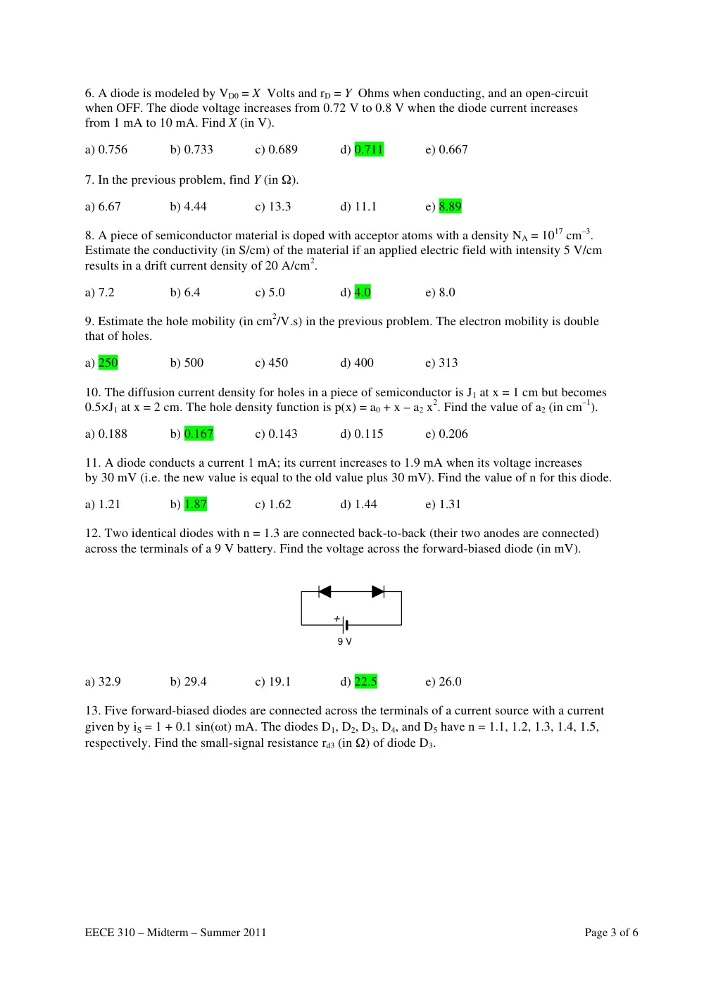
12. Two identical diodes with n = 1.3 are connected back-to-back (their two anodes are connected)
across the terminals of a 9 V battery. Find the voltage across the forward-biased diode (in mV).
9 V
+
�
a) 32.9
b) 29.4
c) 19.1
d) 22.5
e) 26.0
13. Five forward-biased diodes are connected across the terminals of a current source with a current
given by iS = 1 + 0.1 sin(ωt) mA. The diodes D1, D2, D3, D4, and D5 have n = 1.1, 1.2, 1.3, 1.4, 1.5,
respectively. Find the small-signal resistance rd3 (in Ω) of diode D3.
EECE 310 – Midterm – Summer 2011
Page 4 of 6
D1
D2
D3
D4
D5
vo
+
_
iS
�
a) 32.5
b) 21.7
c) 16.3
d) 13.0
e) 10.8
14. Find the peak-to-peak variation in the total voltage vo across the five forward-biased diodes in the
previous problem.
a) 16.3
b) 13.0
c) 10.8
d) 32.5
e) 21.7
15. A Zener diode regulator shown in the circuit below uses a Zener diodes that has VZ = 9 V
at IZT = 20 mA, with rZ = 10 Ω and IZK = 5 mA. The source VA is 15 V, but varies between 13 V and
17 V. The load draws a current that varies from 0 to 10 mA. Find the value of VZ0 (in V) for the Zener
diode.
VA
R
iL
�
a) 6.8
b) 7.8
c) 8.8
d) 9.8
e) 10.8
16. In Problem 15, if the maximum variation in the Zener voltage due to the total variation in the load
current is 92 mV, what should be the value of R (in Ω)? Assume that the source voltage is fixed
at 15 V.
a) 80.9
b) 61.4
c) 48.8
d) 190
e) 115
17. In Problem 15, and in order to maintain regulation under all conditions of vS and iL, what is the
maximum value of R (in Ω)?
a) 143
b) 210
c) 410
d) 343
e) 277
EECE 310 – Midterm – Summer 2011
Page 5 of 6
18. A half-wave rectifier circuit using an ideal diode operates from a 24 V RMS, 50 Hz sinusoidal
source and delivers rectified current to a 1.6 kΩ resistive load. What is the average value of the load
current (in mA)?
a) 6.75
b) 6.00
c) 7.72
d) 10.8
e) 9.00
19. Assume in the previous problem that a capacitor is connected in parallel with the load resistor.
What should the value of this capacitance be (in mF) in order to limit the ripple voltage to 0.5 V?
a) 0.97
b) 0.85
c) 1.36
d) 0.75
e) 1.13
20. A 4-diode bridge rectifier circuit with a resistive load operates from a 220 V RMS sinusoidal
supply through a step-down transformer having a turns ratio of 11-to-1. Each diode is modeled by a
0.7 V drop for any forward current, and an open-circuit when the diode is OFF. What is the peak
inverse voltage (PIV, in V) for the diodes in the circuit?
a) 21.5
b) 23.2
c) 25.2
d) 27.6
e) 30.4
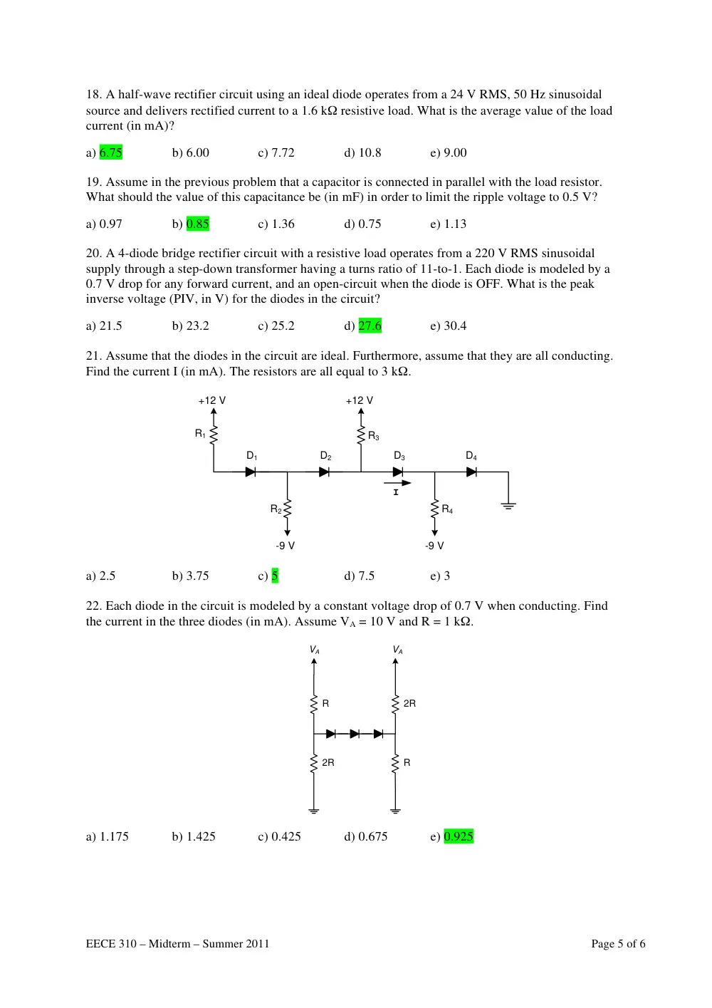
21. Assume that the diodes in the circuit are ideal. Furthermore, assume that they are all conducting.
Find the current I (in mA). The resistors are all equal to 3 kΩ.
+12 V
+12 V
-9 V
-9 V
R1
R2
R3
R4
D1
D2
D3
D4
I
�
a) 2.5
b) 3.75
c) 5
d) 7.5
e) 3
22. Each diode in the circuit is modeled by a constant voltage drop of 0.7 V when conducting. Find
the current in the three diodes (in mA). Assume VA = 10 V and R = 1 kΩ.
2R
R
2R
R
VA
VA
�
a) 1.175
b) 1.425
c) 0.425
d) 0.675
e) 0.925
EECE 310 – Midterm – Summer 2011
Page 6 of 6
23. Find the current flowing out of the 6 V supply (in mA). The diode drops 0.7 V when conducting,
and is an open circuit when it is OFF.
4k
2k
6 V
2 V
2k
�
a) 1
b) 1.2
c) 1.5
d) 1.8
e) 2
24. Find the average value of the output voltage. Assume that the diode is ideal and Vmax = 2 VA.
+
+
-
vO
vI
vI
t
Vmax
-Vmax
R
+
VA
T
T/2
a) –0.5VA
b) VA
c) 0
d) –2Vmax
e) 1.5VA