
EECE 310 Midterm with Solutions, Fall 2014
American University of Beirut · Electronics · 7 pages · with solution

More EECE 310 files
- Midterm · Fall 2014ExamView
- Midterm · Fall 2013ExamView
- Midterm · Fall 2012ExamView
- Midterm with Solution · Summer 2011Exam · with solutionView
- Exam 2 with Answers · Fall 2011Exam · with solutionView
- Exam 1 with Answers · Fall 2011Exam · with solutionView
- Midterm · Summer 2010ExamView
- Exam 1 · Fall 2010ExamView
Show the text of this exam
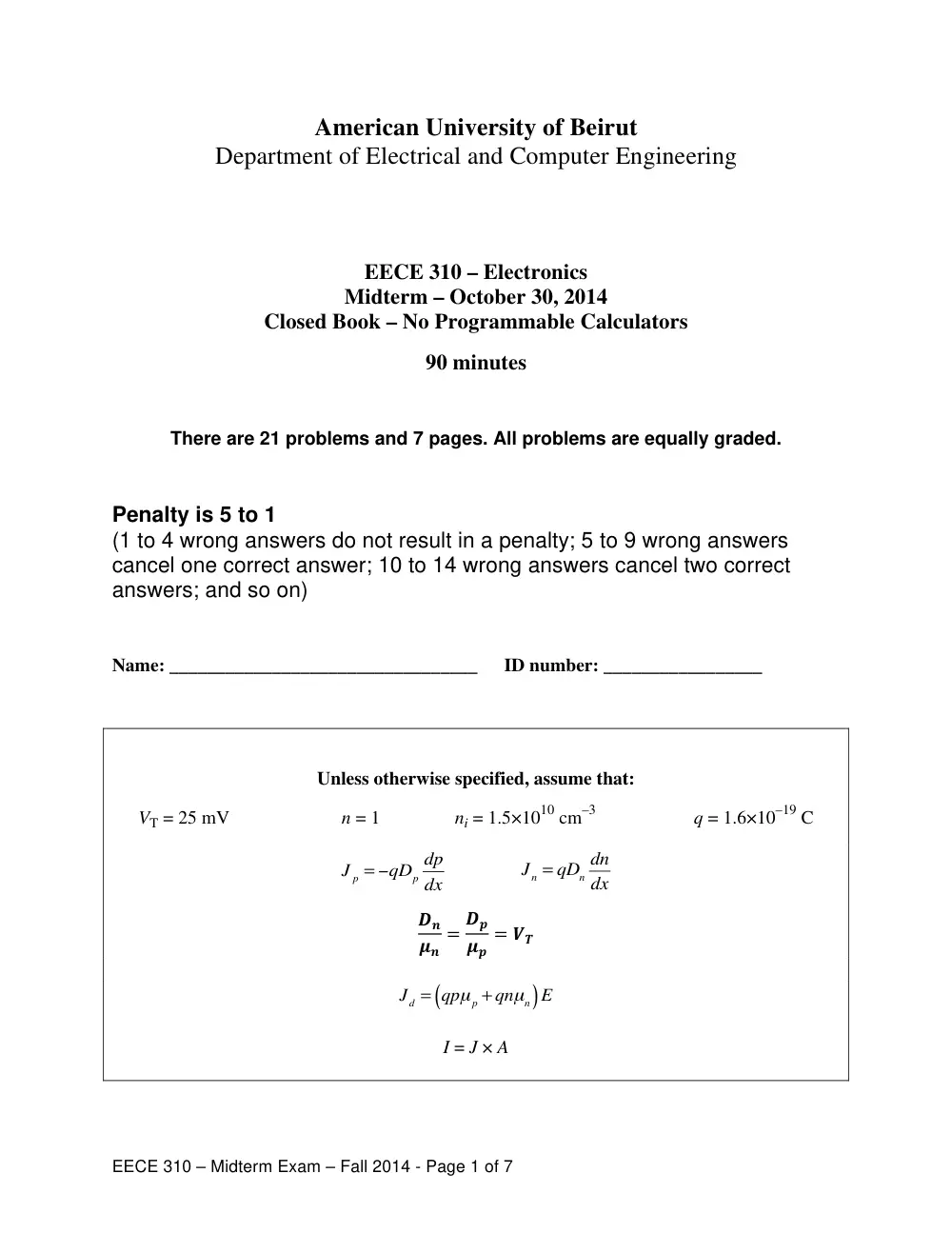
EECE 310 – Midterm Exam – Fall 2014 - Page 1 of 7
American University of Beirut
Department of Electrical and Computer Engineering
EECE 310 – Electronics
Midterm – October 30, 2014
Closed Book – No Programmable Calculators
90 minutes
There are 21 problems and 7 pages. All problems are equally graded.
Penalty is 5 to 1
(1 to 4 wrong answers do not result in a penalty; 5 to 9 wrong answers
cancel one correct answer; 10 to 14 wrong answers cancel two correct
answers; and so on)
Name: _________________________________
ID number: _________________
Unless otherwise specified, assume that:
VT = 25 mV n = 1 ni = 1.5×1010 cm–3 q = 1.6×10⁻¹⁹ C
J p = −qDp
dp
dx J n = qDn
dn
dx
��
��
� ��
��
� ��
J d = qpμ p + qnμn
(
)E
I = J × A
EECE 310 – Midterm Exam – Fall 2014 - Page 2 of 7
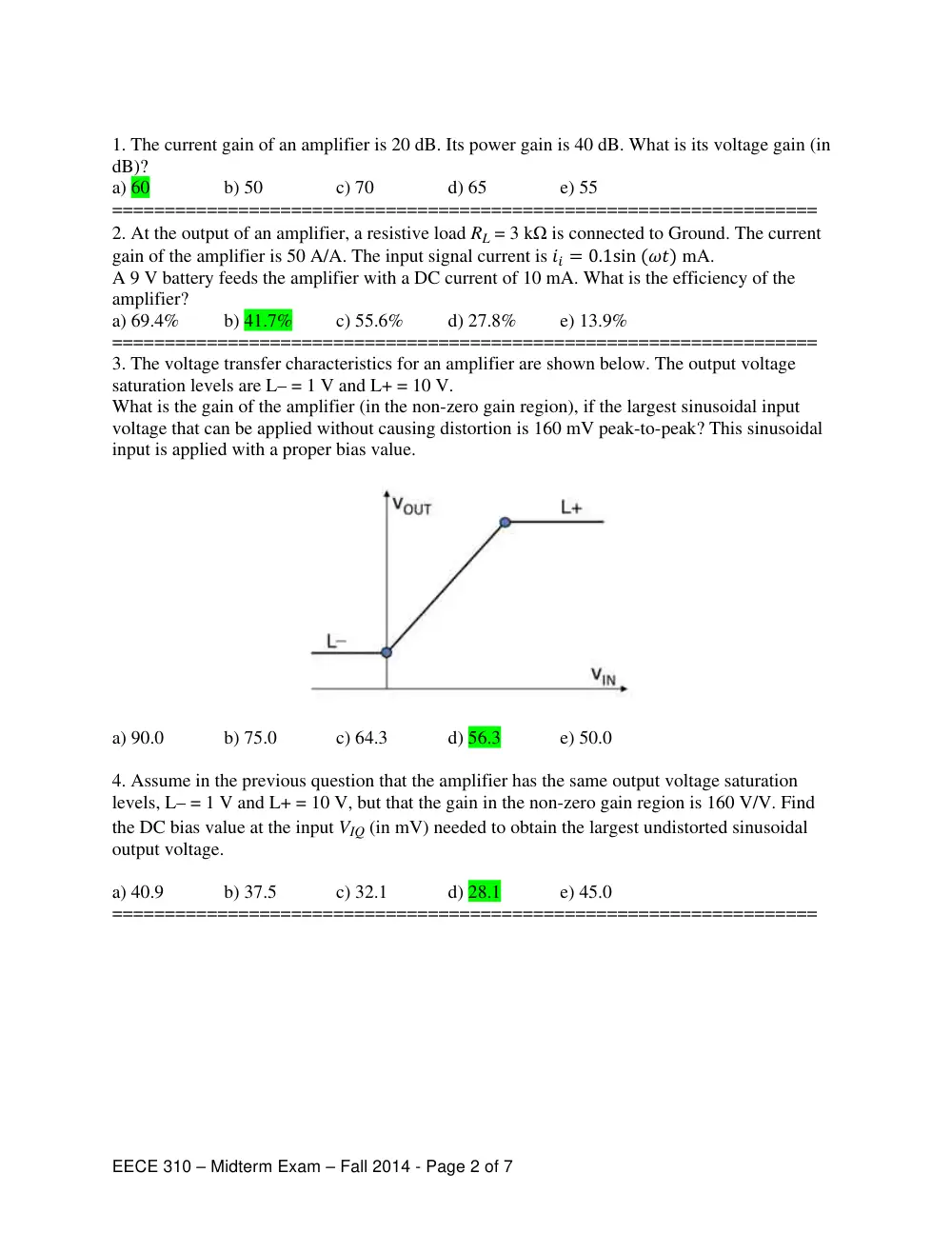
1. The current gain of an amplifier is 20 dB. Its power gain is 40 dB. What is its voltage gain (in
dB)?
a) 60
b) 50
c) 70
d) 65
e) 55
===================================================================
2. At the output of an amplifier, a resistive load RL = 3 kΩ is connected to Ground. The current
gain of the amplifier is 50 A/A. The input signal current is �� � ����������� mA.
A 9 V battery feeds the amplifier with a DC current of 10 mA. What is the efficiency of the
amplifier?
a) 69.4%
b) 41.7%
c) 55.6%
d) 27.8%
e) 13.9%
===================================================================
3. The voltage transfer characteristics for an amplifier are shown below. The output voltage
saturation levels are L– = 1 V and L+ = 10 V.
What is the gain of the amplifier (in the non-zero gain region), if the largest sinusoidal input
voltage that can be applied without causing distortion is 160 mV peak-to-peak? This sinusoidal
input is applied with a proper bias value.
a) 90.0
b) 75.0
c) 64.3
d) 56.3
e) 50.0
4. Assume in the previous question that the amplifier has the same output voltage saturation
levels, L– = 1 V and L+ = 10 V, but that the gain in the non-zero gain region is 160 V/V. Find
the DC bias value at the input VIQ (in mV) needed to obtain the largest undistorted sinusoidal
output voltage.
a) 40.9
b) 37.5
c) 32.1
d) 28.1
e) 45.0
===================================================================
EECE 310 – Midterm Exam – Fall 2014 - Page 3 of 7
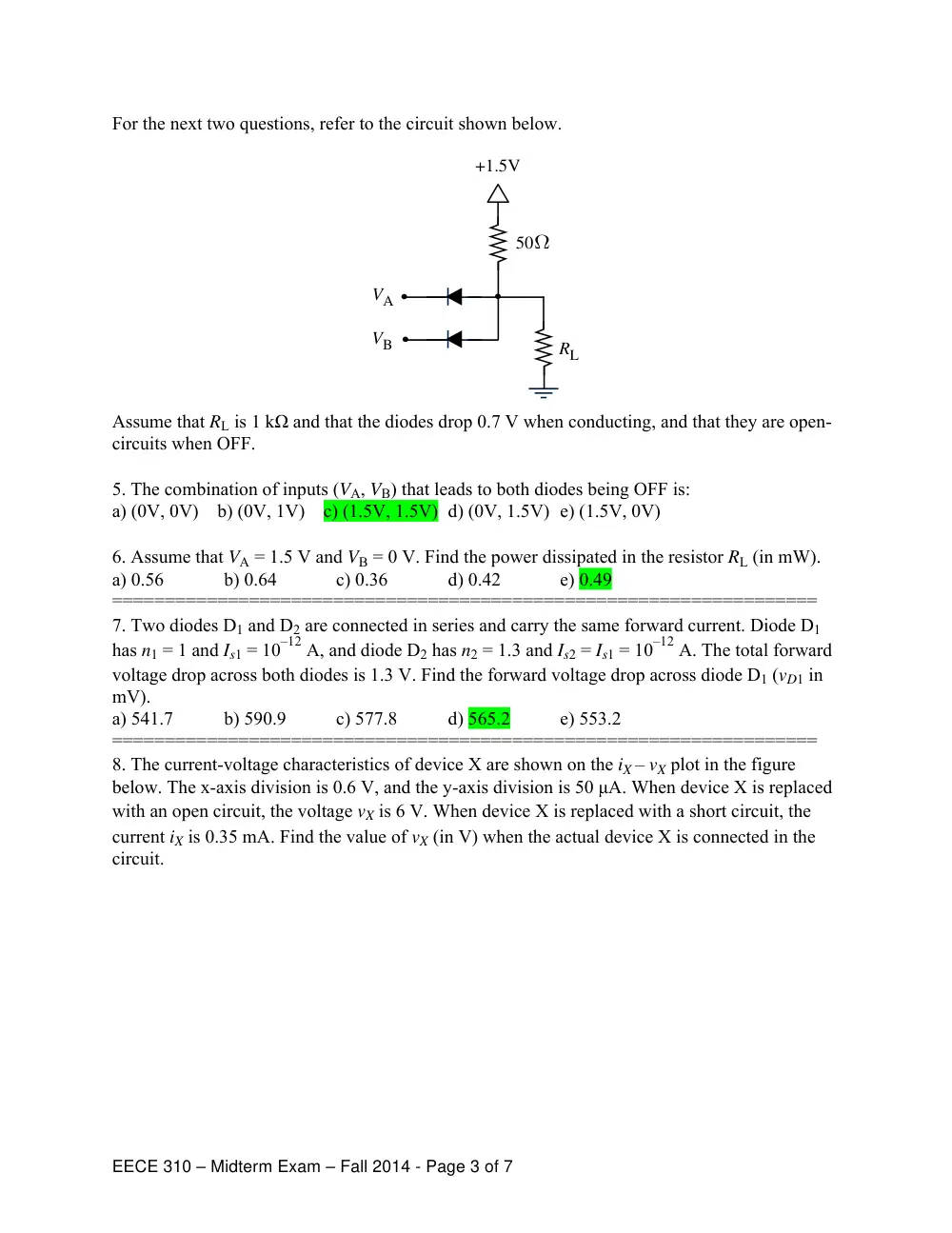
For the next two questions, refer to the circuit shown below.
Assume that RL is 1 kΩ and that the diodes drop 0.7 V when conducting, and that they are open-
circuits when OFF.
5. The combination of inputs (VA, VB) that leads to both diodes being OFF is:
a) (0V, 0V) b) (0V, 1V) c) (1.5V, 1.5V) d) (0V, 1.5V) e) (1.5V, 0V)
6. Assume that VA = 1.5 V and VB = 0 V. Find the power dissipated in the resistor RL (in mW).
a) 0.56
b) 0.64
c) 0.36
d) 0.42
e) 0.49
===================================================================
7. Two diodes D1 and D2 are connected in series and carry the same forward current. Diode D1
has n1 = 1 and Is1 = 10–12 A, and diode D2 has n2 = 1.3 and Is2 = Is1 = 10–12 A. The total forward
voltage drop across both diodes is 1.3 V. Find the forward voltage drop across diode D1 (vD1 in
mV).
a) 541.7
b) 590.9
c) 577.8
d) 565.2
e) 553.2
===================================================================
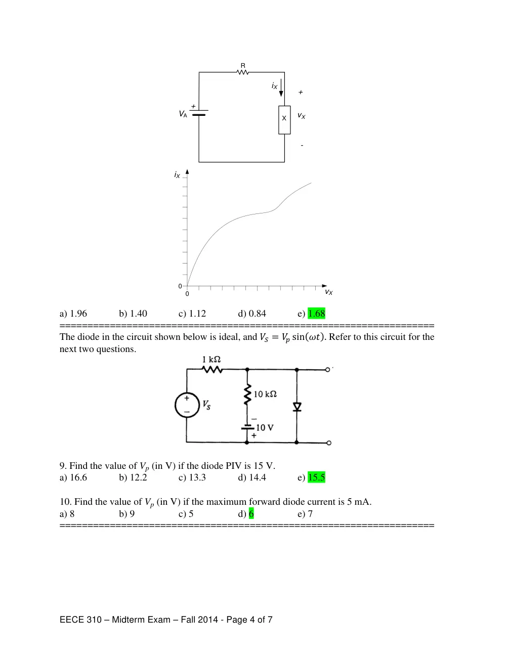
8. The current-voltage characteristics of device X are shown on the iX – vX plot in the figure
below. The x-axis division is 0.6 V, and the y-axis division is 50 μA. When device X is replaced
with an open circuit, the voltage vX is 6 V. When device X is replaced with a short circuit, the
current iX is 0.35 mA. Find the value of vX (in V) when the actual device X is connected in the
circuit.
VA
VB
50Ω
+1.5V
RL
EECE 310 – Midterm Exam – Fall 2014 - Page 4 of 7
a) 1.96
b) 1.40
c) 1.12
d) 0.84
e) 1.68
===================================================================
The diode in the circuit shown below is ideal, and �� � �� ��� �� � Refer to this circuit for the
next two questions.
9. Find the value of Vp (in V) if the diode PIV is 15 V.
a) 16.6
b) 12.2
c) 13.3
d) 14.4
e) 15.5
10. Find the value of Vp (in V) if the maximum forward diode current is 5 mA.
a) 8
b) 9
c) 5
d) 6
e) 7
===================================================================
+
+
-
vX
VA
R
iX
vX
iX
0
0
X
EECE 310 – Midterm Exam – Fall 2014 - Page 5 of 7
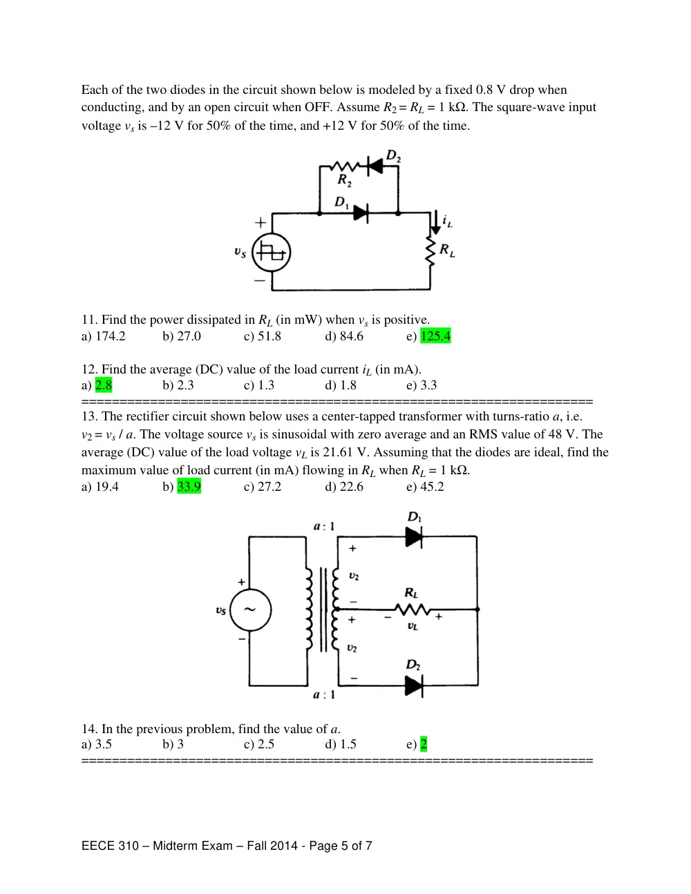
Each of the two diodes in the circuit shown below is modeled by a fixed 0.8 V drop when
conducting, and by an open circuit when OFF. Assume R2 = RL = 1 kΩ. The square-wave input
voltage vs is –12 V for 50% of the time, and +12 V for 50% of the time.
11. Find the power dissipated in RL (in mW) when vs is positive.
a) 174.2
b) 27.0
c) 51.8
d) 84.6
e) 125.4
12. Find the average (DC) value of the load current iL (in mA).
a) 2.8
b) 2.3
c) 1.3
d) 1.8
e) 3.3
===================================================================
13. The rectifier circuit shown below uses a center-tapped transformer with turns-ratio a, i.e.
v2 = vs / a. The voltage source vs is sinusoidal with zero average and an RMS value of 48 V. The
average (DC) value of the load voltage vL is 21.61 V. Assuming that the diodes are ideal, find the
maximum value of load current (in mA) flowing in RL when RL = 1 kΩ.
a) 19.4
b) 33.9
c) 27.2
d) 22.6
e) 45.2
14. In the previous problem, find the value of a.
a) 3.5
b) 3
c) 2.5
d) 1.5
e) 2
===================================================================
EECE 310 – Midterm Exam – Fall 2014 - Page 6 of 7
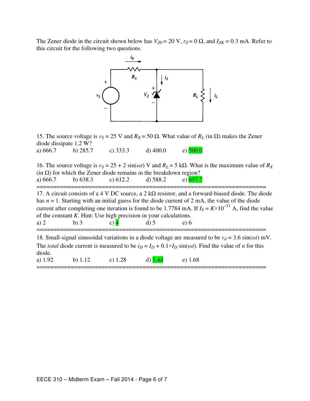
The Zener diode in the circuit shown below has VZ0 = 20 V, rZ = 0 Ω, and IZK = 0.3 mA. Refer to
this circuit for the following two questions.
15. The source voltage is vS = 25 V and RX = 50 Ω. What value of RL (in Ω) makes the Zener
diode dissipate 1.2 W?
a) 666.7
b) 285.7
c) 333.3
d) 400.0
e) 500.0
16. The source voltage is vS = 25 + 2 sin(ωt) V and RL = 5 kΩ. What is the maximum value of RX
(in Ω) for which the Zener diode remains in the breakdown region?
a) 666.7
b) 638.3
c) 612.2
d) 588.2
e) 697.7
===================================================================
17. A circuit consists of a 4 V DC source, a 2 kΩ resistor, and a forward-biased diode. The diode
has n = 1. Starting with an initial guess for the diode current of 2 mA, the value of the diode
current after completing one iteration is found to be 1.7784 mA. If IS = K×10–11 A, find the value
of the constant K. Hint: Use high precision in your calculations.
a) 2
b) 3
c) 4
d) 5
e) 6
===================================================================
18. Small-signal sinusoidal variations in a diode voltage are measured to be vd = 3.6 sin(ωt) mV.
The total diode current is measured to be iD = ID + 0.1×ID sin(ωt). Find the value of n for this
diode.
a) 1.92
b) 1.12
c) 1.28
d) 1.44
e) 1.68
===================================================================
EECE 310 – Midterm Exam – Fall 2014 - Page 7 of 7
The doping concentration (density) profile of donor atoms in a piece of semiconductor material
of length L is given by ND(x) = N0 + N1(x/L)3 for 0 ≤ x ≤ L with N0 = 1016 cm–3,
N1 = 3×1016 cm–3, and L = 0.1 cm. The mobility of free electrons is 1000 cm2/V.s, and the
mobility of holes is 500 cm2/V.s.
19. The free electron concentration (density) is largest at x = x1, and the hole concentration
(density) is largest at x = x2. Find x1 and x2.
a) x1 = L, x2 = 0
b) x1 = L/2, x2 = L/2
c) x1 = 0, x2 = 0
d) x1 = 0, x2 = L
e) x1 = L, x2 = L
20. What is free electron diffusion current density (in A/cm2) at x = L/2?
a) 0.6
b) 0.9
c) 1.2
d) 1.5
e) 1.8
21. Assume in this question that the total diffusion current density at x = L is 8 A/cm2. Under
equilibrium conditions, the total current density should be zero. Find the magnitude of the
electric field E (in V/cm) at x = L that must exist to maintain the equilibrium.
a) 1.00
b) 0.83
c) 1.25
d) 1.67
e) 0.71
===================================================================