
EECE 310 Midterm, Fall 2013
American University of Beirut · Electronics · 6 pages
More EECE 310 files
- Midterm with Solutions · Fall 2014Exam · with solutionView
- Midterm · Fall 2014ExamView
- Midterm · Fall 2012ExamView
- Midterm with Solution · Summer 2011Exam · with solutionView
- Exam 2 with Answers · Fall 2011Exam · with solutionView
- Exam 1 with Answers · Fall 2011Exam · with solutionView
- Midterm · Summer 2010ExamView
- Exam 1 · Fall 2010ExamView
Show the text of this exam
EECE 310 – Midterm Exam – Fall 2013 - Page 1 of 6
American University of Beirut
Department of Electrical and Computer Engineering
EECE 310 – Electronics
Midterm – October 24, 2013
Closed Book – No Programmable Calculators
90 minutes
There are 21 problems and 6 pages. All problems are equally graded.
Penalty is 5 to 1
(1 to 4 wrong answers do not result in a penalty; 5 to 9 wrong answers
cancel one correct answer; 10 to 14 wrong answers cancel two correct
answers; and so on)
Name: _________________________________
ID number: _________________
Unless otherwise specified, assume that:
VT = 25 mV n = 1 ni = 1.5×1010 cm–3 q = 1.6×10⁻¹⁹ C
J p = −qDp
dp
dx J n = qDn
dn
dx
𝑫𝒏
𝝁𝒏
=
𝑫𝒑
𝝁𝒑
= 𝑽𝑻
J d = qpµ p + qnµn
(
)E
I = J × A
EECE 310 – Midterm Exam – Fall 2013 - Page 2 of 6
===================================================================
The efficiency of an amplifier loaded by a 1 kΩ resistor is 43%. The amplifier is powered from a
single 8 V DC supply. The supply current is 10 mA. The voltage gain of the amplifier is 45 dB.
The input and output voltages are sine waves with zero average.
1. Find the power dissipated (lost) in the amplifier (in mW).
a) 65.6
b) 53.6
c) 61.6
d) 45.6
e) 69.6
2. Find the peak value of the input voltage in (in mV).
a) 34.11
b) 30.18
c) 25.65
d) 46.64
e) 40.86
===================================================================
3. A large forward current is flowing in a Silicon diode. When the diode voltage increases by
Δ = 27 mV (from VD to VD + Δ), this current doubles (from ID to 2ID). Find the value of n for this
diode.
a) 1.21
b) 1.33
c) 1.44
d) 1.56
e) 1.67
===================================================================
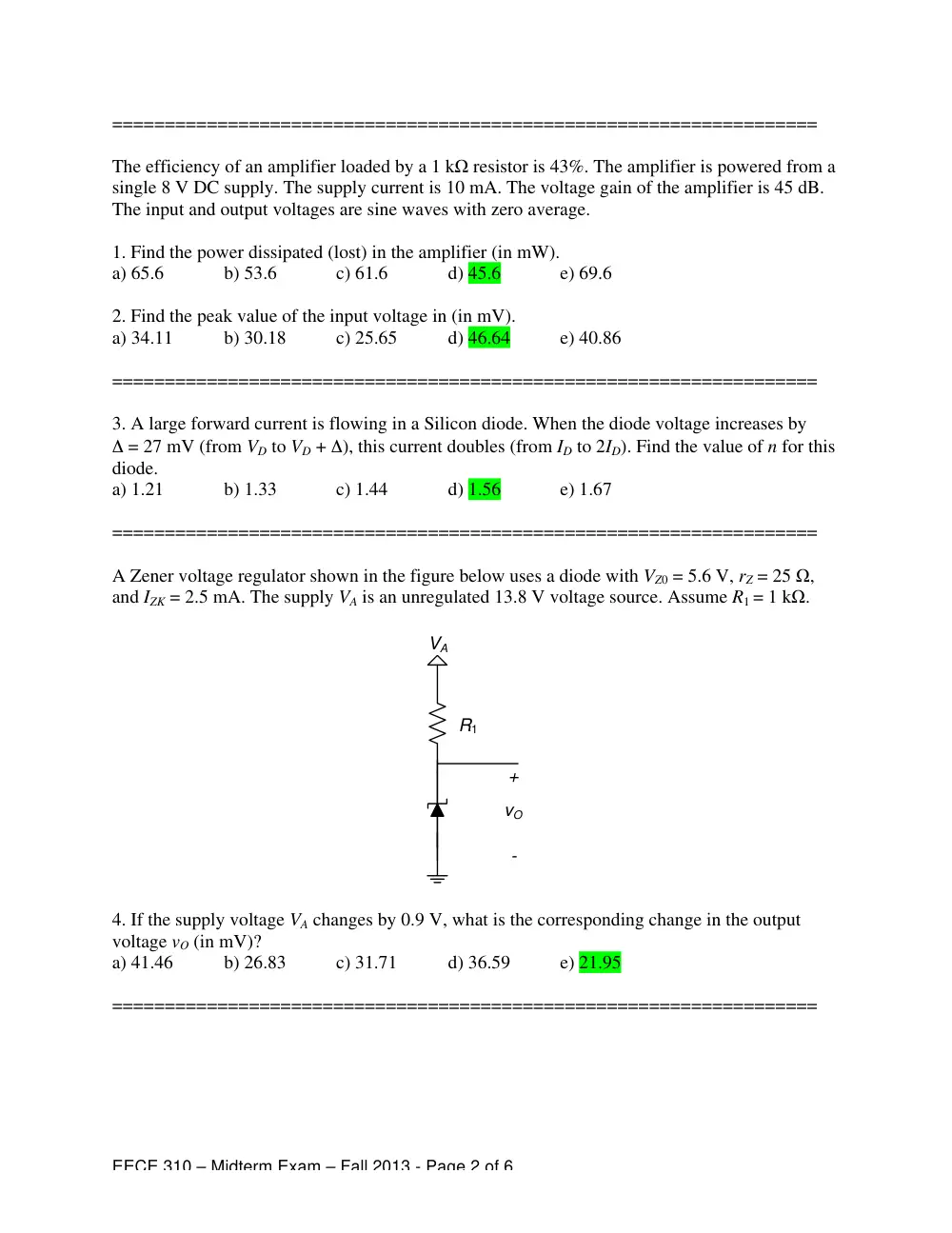
A Zener voltage regulator shown in the figure below uses a diode with VZ0 = 5.6 V, rZ = 25 Ω,
and IZK = 2.5 mA. The supply VA is an unregulated 13.8 V voltage source. Assume R1 = 1 kΩ.
VA
R1
vO
+
-
4. If the supply voltage VA changes by 0.9 V, what is the corresponding change in the output
voltage vO (in mV)?
a) 41.46
b) 26.83
c) 31.71
d) 36.59
e) 21.95
===================================================================
EECE 310 – Midterm Exam – Fall 2013 - Page 3 of 6
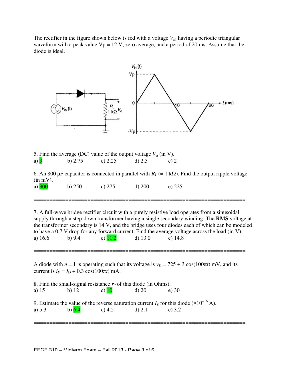
The rectifier in the figure shown below is fed with a voltage Vin having a periodic triangular
waveform with a peak value Vp = 12 V, zero average, and a period of 20 ms. Assume that the
diode is ideal.
5. Find the average (DC) value of the output voltage Vo (in V).
a) 3
b) 2.75
c) 2.25
d) 2.5
e) 2
6. An 800 µF capacitor is connected in parallel with RL (= 1 kΩ). Find the output ripple voltage
(in mV).
a) 300
b) 250
c) 275
d) 200
e) 225
===================================================================
7. A full-wave bridge rectifier circuit with a purely resistive load operates from a sinusoidal
supply through a step-down transformer having a single secondary winding. The RMS voltage at
the transformer secondary is 14 V, and the bridge uses four diodes each of which can be modeled
to have a 0.7 V drop for any forward current. Find the average voltage across the load (in V).
a) 16.6
b) 9.4
c) 11.2
d) 13.0
e) 14.8
===================================================================
A diode with n = 1 is operating such that its voltage is vD = 725 + 3 cos(100πt) mV, and its
current is iD = ID + 0.3 cos(100πt) mA.
8. Find the small-signal resistance rd of this diode (in Ohms).
a) 15
b) 12
c) 10
d) 20
e) 30
9. Estimate the value of the reverse saturation current IS for this diode (×10–16 A).
a) 5.3
b) 6.4
c) 4.2
d) 2.1
e) 3.2
===================================================================
EECE 310 – Midterm Exam – Fall 2013 - Page 4 of 6
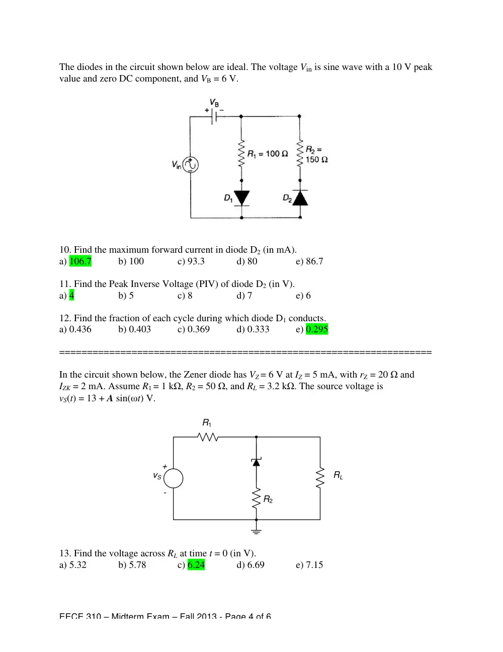
The diodes in the circuit shown below are ideal. The voltage Vin is sine wave with a 10 V peak
value and zero DC component, and VB = 6 V.
10. Find the maximum forward current in diode D2 (in mA).
a) 106.7
b) 100
c) 93.3
d) 80
e) 86.7
11. Find the Peak Inverse Voltage (PIV) of diode D2 (in V).
a) 4
b) 5
c) 8
d) 7
e) 6
12. Find the fraction of each cycle during which diode D1 conducts.
a) 0.436
b) 0.403
c) 0.369
d) 0.333
e) 0.295
===================================================================
In the circuit shown below, the Zener diode has VZ = 6 V at IZ = 5 mA, with rZ = 20 Ω and
IZK = 2 mA. Assume R1 = 1 kΩ, R2 = 50 Ω, and RL = 3.2 kΩ. The source voltage is
vS(t) = 13 + A sin(ωt) V.
R1
R2
RL
vS
+
-
13. Find the voltage across RL at time t = 0 (in V).
a) 5.32
b) 5.78
c) 6.24
d) 6.69
e) 7.15
EECE 310 – Midterm Exam – Fall 2013 - Page 5 of 6
14. Find the maximum value of A (in V) to keep the Zener diode operating in the breakdown
region.
a) 3.07
b) 2.42
c) 1.76
d) 3.73
e) 4.39
===================================================================
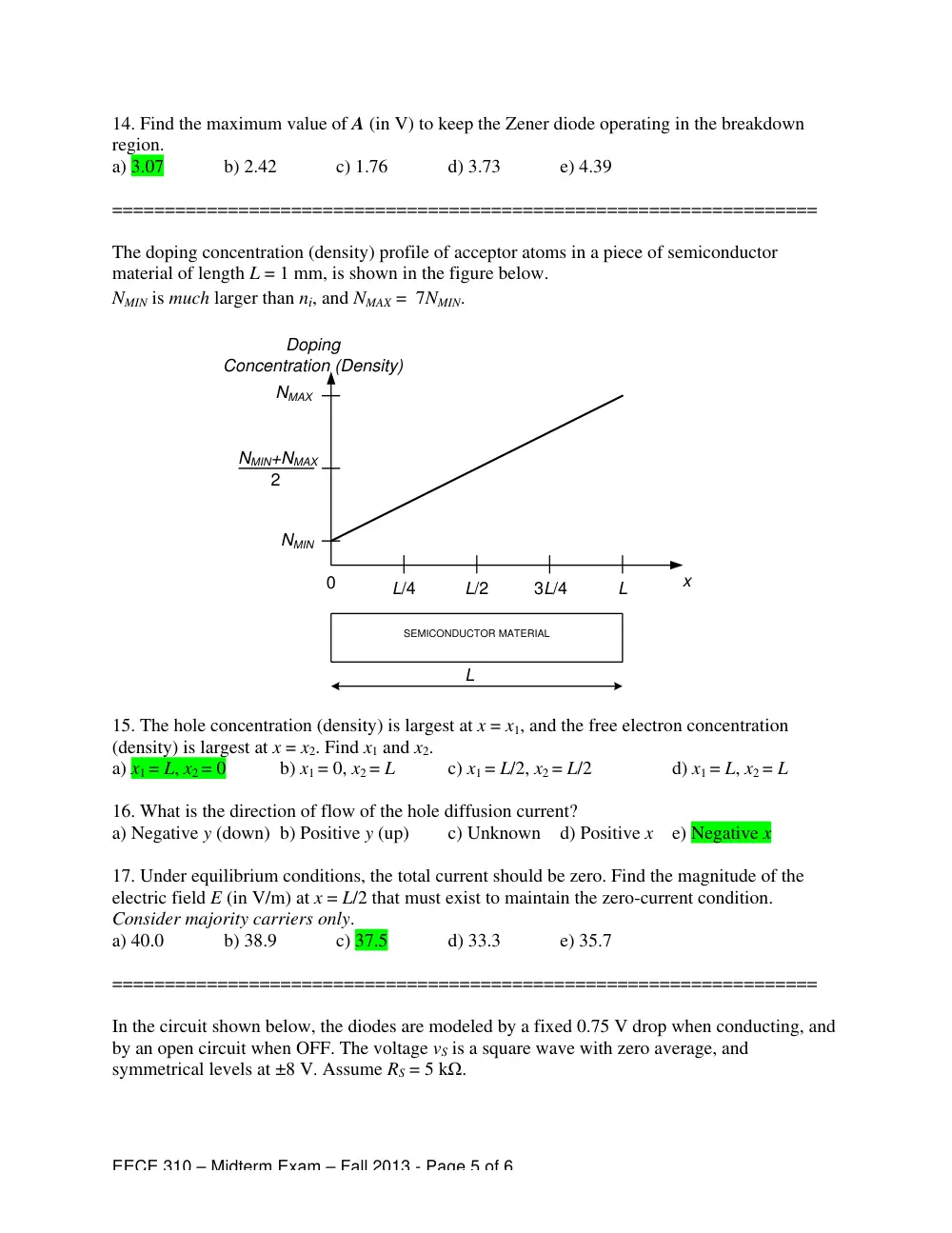
The doping concentration (density) profile of acceptor atoms in a piece of semiconductor
material of length L = 1 mm, is shown in the figure below.
NMIN is much larger than ni, and NMAX = 7NMIN.
SEMICONDUCTOR MATERIAL
x
L
L/2
L/4
3L/4
0
L
Doping
Concentration (Density)
NMIN
NMAX
NMIN+NMAX
2
15. The hole concentration (density) is largest at x = x1, and the free electron concentration
(density) is largest at x = x2. Find x1 and x2.
a) x1 = L, x2 = 0
b) x1 = 0, x2 = L
c) x1 = L/2, x2 = L/2
d) x1 = L, x2 = L
16. What is the direction of flow of the hole diffusion current?
a) Negative y (down) b) Positive y (up)
c) Unknown d) Positive x e) Negative x
17. Under equilibrium conditions, the total current should be zero. Find the magnitude of the
electric field E (in V/m) at x = L/2 that must exist to maintain the zero-current condition.
Consider majority carriers only.
a) 40.0
b) 38.9
c) 37.5
d) 33.3
e) 35.7
===================================================================
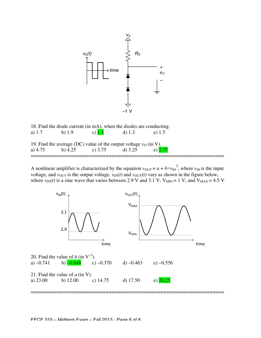
In the circuit shown below, the diodes are modeled by a fixed 0.75 V drop when conducting, and
by an open circuit when OFF. The voltage vS is a square wave with zero average, and
symmetrical levels at ±8 V. Assume RS = 5 kΩ.
EECE 310 – Midterm Exam – Fall 2013 - Page 6 of 6
vS
–1 V
RS
vO
+
–
vS(t)
time
18. Find the diode current (in mA), when the diodes are conducting.
a) 1.7
b) 1.9
c) 1.1
d) 1.3
e) 1.5
19. Find the average (DC) value of the output voltage vO (in V).
a) 4.75
b) 4.25
c) 3.75
d) 3.25
e) 2.75
===================================================================
A nonlinear amplifier is characterized by the equation vOUT = a + b×vIN
3, where vIN is the input
voltage, and vOUT is the output voltage. vIN(t) and vOUT(t) vary as shown in the figure below,
where vIN(t) is a sine wave that varies between 2.9 V and 3.1 V, VMIN = 1 V, and VMAX = 4.5 V.
20. Find the value of b (in V–2).
a) –0.741
b) –0.648
c) –0.370
d) –0.463
e) –0.556
21. Find the value of a (in V).
a) 23.00
b) 12.00
c) 14.75
d) 17.50
e) 20.25
===================================================================
time
vIN(t)
3.1
2.9
time
vOUT(t)
VMAX
VMIN