
EECE 310 Exam 1, Fall 2007
American University of Beirut · Electronics · 5 pages
More EECE 310 files
- Midterm · Fall 2014ExamView
- Midterm with Solutions · Fall 2014Exam · with solutionView
- Midterm · Fall 2013ExamView
- Midterm · Fall 2012ExamView
- Exam 2 with Answers · Fall 2011Exam · with solutionView
- Exam 1 with Answers · Fall 2011Exam · with solutionView
- Midterm with Solution · Summer 2011Exam · with solutionView
- Exam 1 · Fall 2010ExamView
Show the text of this exam
EECE 310 Electronics – Section 1
Quiz 1 – November 3, 2007
CLOSED BOOK – One and One-Half Hours
Penalty 5:1 on Questions 1 - 7
(7%)
1.
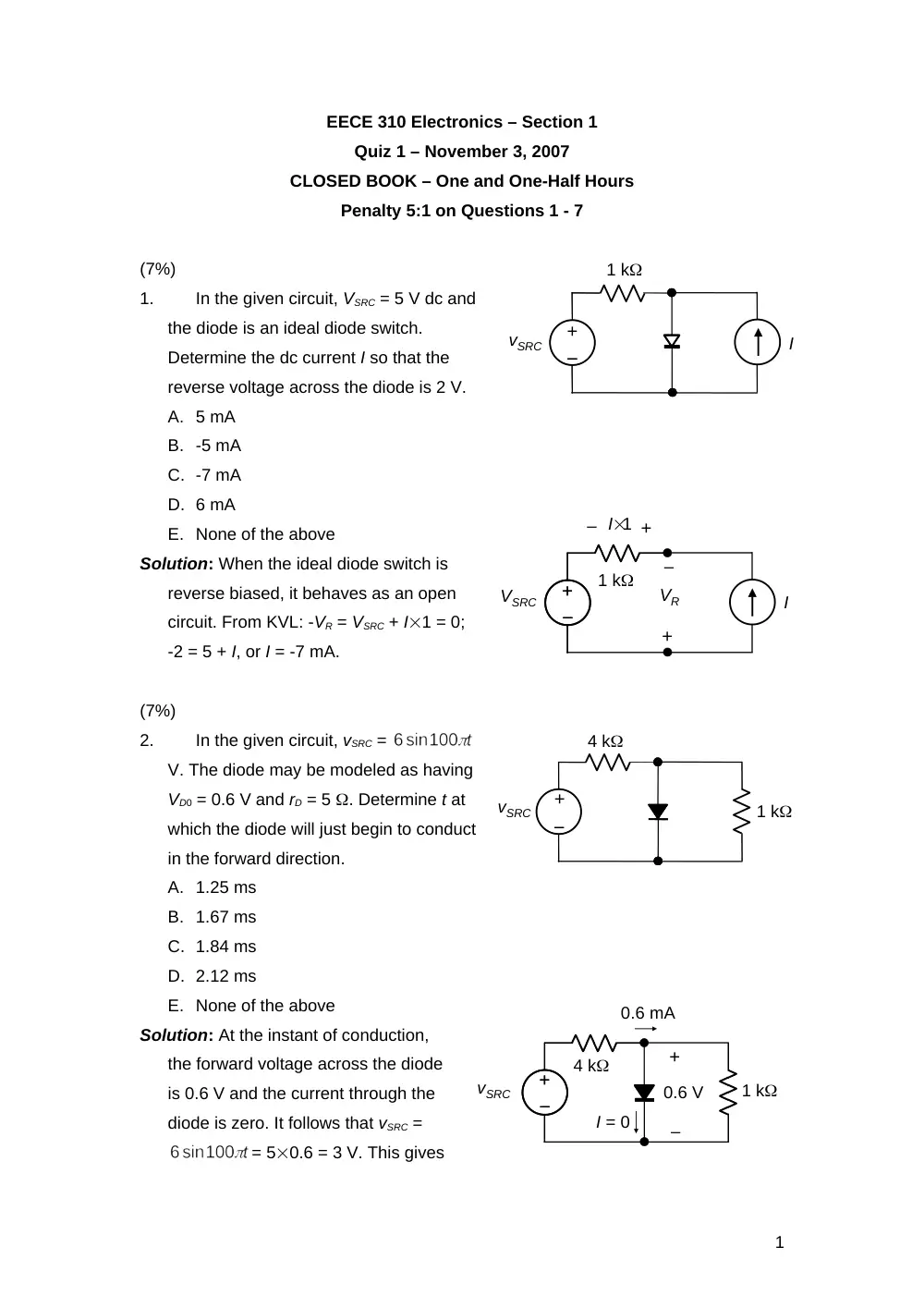
In the given circuit, VSRC = 5 V dc and
the diode is an ideal diode switch.
Determine the dc current I so that the
reverse voltage across the diode is 2 V.
A. 5 mA
B. -5 mA
C. -7 mA
D. 6 mA
E. None of the above
Solution: When the ideal diode switch is
reverse biased, it behaves as an open
circuit. From KVL: -VR = VSRC + I1 = 0;
-2 = 5 + I, or I = -7 mA.
(7%)
2.
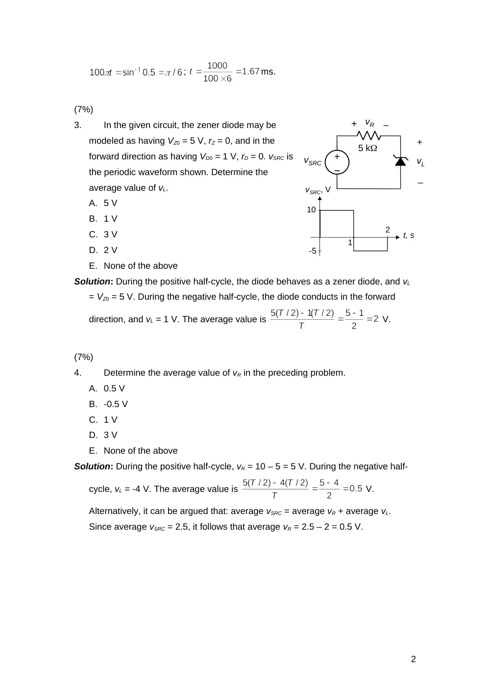
In the given circuit, vSRC =
V. The diode may be modeled as having
VD0 = 0.6 V and rD = 5 . Determine t at
which the diode will just begin to conduct
in the forward direction.
A. 1.25 ms
B. 1.67 ms
C. 1.84 ms
D. 2.12 ms
E. None of the above
Solution: At the instant of conduction,
the forward voltage across the diode
is 0.6 V and the current through the
diode is zero. It follows that vSRC =
= 50.6 = 3 V. This gives
1
–
+
–
+
VSRC
1 k
I
+
–
VR
+
– I1
–
+
–
+
vSRC
1 k
+
–
0.6 V
I = 0
0.6 mA
4 k
–
+
–
vSRC
1 k
4 k
–
+
–
vSRC
1 k
I
;
ms.
(7%)
3.
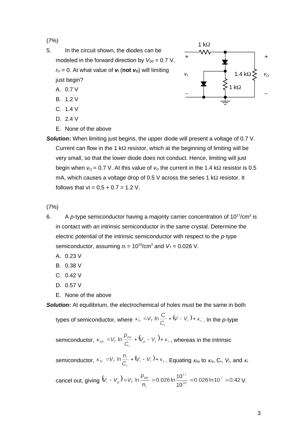
In the given circuit, the zener diode may be
modeled as having VZ0 = 5 V, rZ = 0, and in the
forward direction as having VD0 = 1 V, rD = 0. vSRC is
the periodic waveform shown. Determine the
average value of vL.
A. 5 V
B. 1 V
C. 3 V
D. 2 V
E. None of the above
Solution: During the positive half-cycle, the diode behaves as a zener diode, and vL
= VZ0 = 5 V. During the negative half-cycle, the diode conducts in the forward
direction, and vL = 1 V. The average value is
V.
(7%)
4.
Determine the average value of vR in the preceding problem.
A. 0.5 V
B. -0.5 V
C. 1 V
D. 3 V
E. None of the above
Solution: During the positive half-cycle, vR = 10 – 5 = 5 V. During the negative half-
cycle, vL = -4 V. The average value is
V.
Alternatively, it can be argued that: average vSRC = average vR + average vL.
Since average vSRC = 2.5, it follows that average vR = 2.5 – 2 = 0.5 V.
2
–
+
–
vSRC
5 k
+
–
vL
+
–
vR
t, s
vSRC, V
10
-5
1
2
(7%)
5.
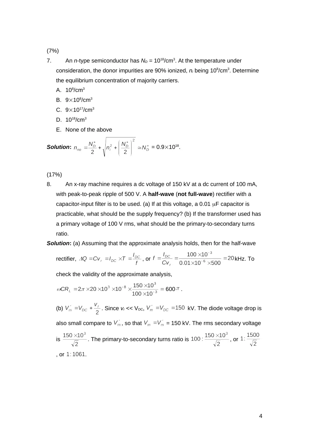
In the circuit shown, the diodes can be
modeled in the forward direction by VD0 = 0.7 V,
rD = 0. At what value of vI (not vO) will limiting
just begin?
A. 0.7 V
B. 1.2 V
C. 1.4 V
D. 2.4 V
E. None of the above
Solution: When limiting just begins, the upper diode will present a voltage of 0.7 V.
Current can flow in the 1 k resistor, which at the beginning of limiting will be
very small, so that the lower diode does not conduct. Hence, limiting will just
begin when vO = 0.7 V. At this value of vO the current in the 1.4 k resistor is 0.5
mA, which causes a voltage drop of 0.5 V across the series 1 k resistor. It
follows that vI = 0.5 + 0.7 = 1.2 V.
(7%)
6.
A p-type semiconductor having a majority carrier concentration of 1017/cm3 is
in contact with an intrinsic semiconductor in the same crystal. Determine the
electric potential of the intrinsic semiconductor with respect to the p-type
semiconductor, assuming ni = 1010/cm3 and VT = 0.026 V.
A. 0.23 V
B. 0.38 V
C. 0.42 V
D. 0.57 V
E. None of the above
Solution: At equilibrium, the electrochemical of holes must be the same in both
types of semiconductor, where
. In the p-type
semiconductor,
, whereas in the intrinsic
semiconductor,
. Equating hp to hi, Cr, Vr, and r
cancel out, giving
V.
3
1 k
+
–
vO
1.4 k
1 k
+
–
vI
(7%)
7.
An n-type semiconductor has ND = 1018/cm3. At the temperature under
consideration, the donor impurities are 90% ionized, ni being 108/cm3. Determine
the equilibrium concentration of majority carriers.
A. 108/cm3
B. 9108/cm3
C. 91017/cm3
D. 1018/cm3
E. None of the above
Solution:
= 0.91018.
(17%)
8.
An x-ray machine requires a dc voltage of 150 kV at a dc current of 100 mA,
with peak-to-peak ripple of 500 V. A half-wave (not full-wave) rectifier with a
capacitor-input filter is to be used. (a) If at this voltage, a 0.01 F capacitor is
practicable, what should be the supply frequency? (b) If the transformer used has
a primary voltage of 100 V rms, what should be the primary-to-secondary turns
ratio.
Solution: (a) Assuming that the approximate analysis holds, then for the half-wave
rectifier,
, or
kHz. To
check the validity of the approximate analysis,
600
.
(b)
. Since vr << VDC,
kV. The diode voltage drop is
also small compare to
, so that
= 150 kV. The rms secondary voltage
is
. The primary-to-secondary turns ratio is
, or
, or
.
4
(17%)
9.
Given a zener diode regulator using a zener diode of VZ0 = 9 V and IZmin = 2
mA. The input varies between VImax and VImin, where VImax – VImin = 5 V. A variation
of the load current between zero and 20 mA, at constant input voltage, changes
the load voltage by 0.2 V. A change in the input voltage between VImax and VImin
changes the load voltage by 0.1 V, at a constant load current of 20 mA.
Determine: (a) RS; (b) rZ; (c) VZ at IZ = 10 mA; (d) VImin; and (e) minimum power
rating of zener diode.
Solution: At constant input voltage,
, or,
. At
constant load current:
. Dividing gives:
(a)
.
(b) It follows that
, so that
.
(c)
9.10 V;
(d) At IZ = 2 mA,
V;
V;
(e)
, which gives
mA,
9.32 V; minimum power rating of zener diode = 9.320.0314 = 0.293 W.
(17%)
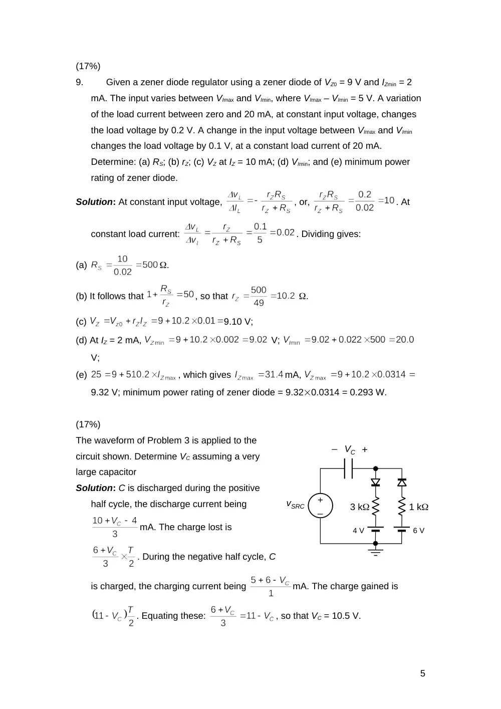
The waveform of Problem 3 is applied to the
circuit shown. Determine VC assuming a very
large capacitor
Solution: C is discharged during the positive
half cycle, the discharge current being
mA. The charge lost is
. During the negative half cycle, C
is charged, the charging current being
mA. The charge gained is
. Equating these:
, so that VC = 10.5 V.
5
vSRC
VC
3 k
_
+
+
_
1 k
4 V
6 V