
EECE 310 Exam 1, Fall 2009
American University of Beirut · Electronics · 6 pages


More EECE 310 files
- Midterm · Fall 2014ExamView
- Midterm with Solutions · Fall 2014Exam · with solutionView
- Midterm · Fall 2013ExamView
- Midterm · Fall 2012ExamView
- Exam 2 with Answers · Fall 2011Exam · with solutionView
- Midterm with Solution · Summer 2011Exam · with solutionView
- Exam 1 with Answers · Fall 2011Exam · with solutionView
- Exam 1 · Fall 2010ExamView
Show the text of this exam
EECE 310 – Quiz 1 – Fall 2009-2010
Page 1 of 6
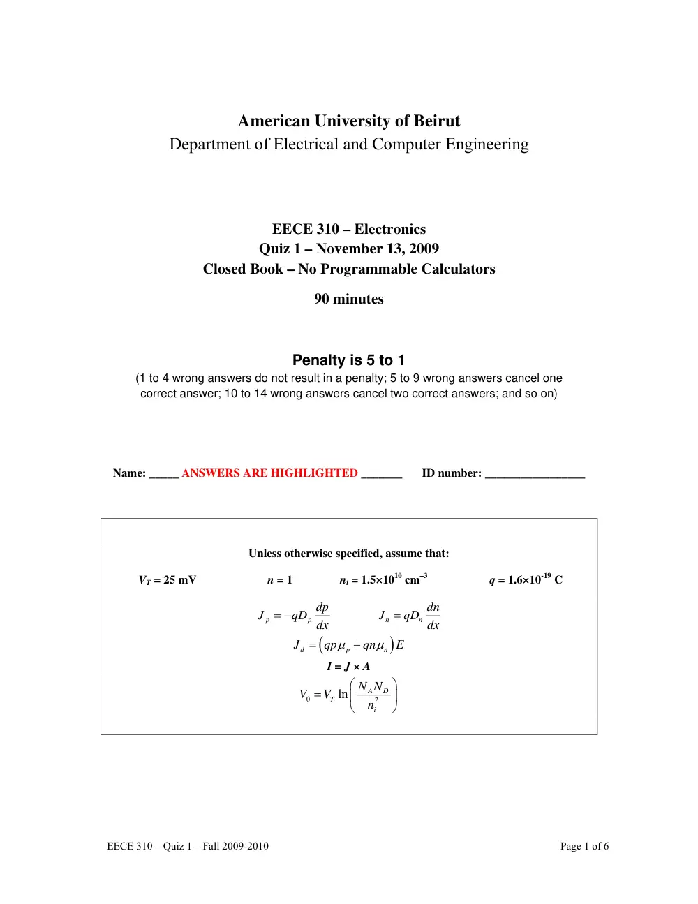
American University of Beirut
Department of Electrical and Computer Engineering
EECE 310 – Electronics
Quiz 1 – November 13, 2009
Closed Book – No Programmable Calculators
90 minutes
Penalty is 5 to 1
(1 to 4 wrong answers do not result in a penalty; 5 to 9 wrong answers cancel one
correct answer; 10 to 14 wrong answers cancel two correct answers; and so on)
Name: _____ ANSWERS ARE HIGHLIGHTED _______
ID number: _________________
Unless otherwise specified, assume that:
VT = 25 mV n = 1 ni = 1.5×1010 cm–3 q = 1.6×10⁻¹⁹ C
p
p
dp
J
= −qD dx
n
n
dn
J
= qD dx
(
)
d
p
n
J
qp
qn
E
μ
μ
=
+
I = J × A
0
2
ln
A
D
T
i
N N
V
V
n
⎛
⎞
=
⎜
⎟
⎝
⎠
EECE 310 – Quiz 1 – Fall 2009-2010
Page 2 of 6
1. The voltage gain of an amplifier is 100. Its current gain is 550.
Find the amplifier power gain, in dB.
a) 46.0
b) 47.4
c) 41.8
d) 43.0
e) 44.8
- - - - - - - - - - - - - - - - - - - - - - - - - - - - - - - - - - - - - - - - - - - - - - - - - - - - - - - - - - - - - - - - - - - - -
2. A voltage amplifier is powered by a single 10 V DC supply. The average DC supply current is 100
mA. The amplifier is loaded by a 50 Ohm resistor. Find the peak-to-peak sinusoidal output voltage
across the load (in V) if the efficiency of the amplifier is 9%.
a) 6.0
b) 6.6
c) 7.2
d) 4.5
e) 5.3
- - - - - - - - - - - - - - - - - - - - - - - - - - - - - - - - - - - - - - - - - - - - - - - - - - - - - - - - - - - - - - - - - - - - -
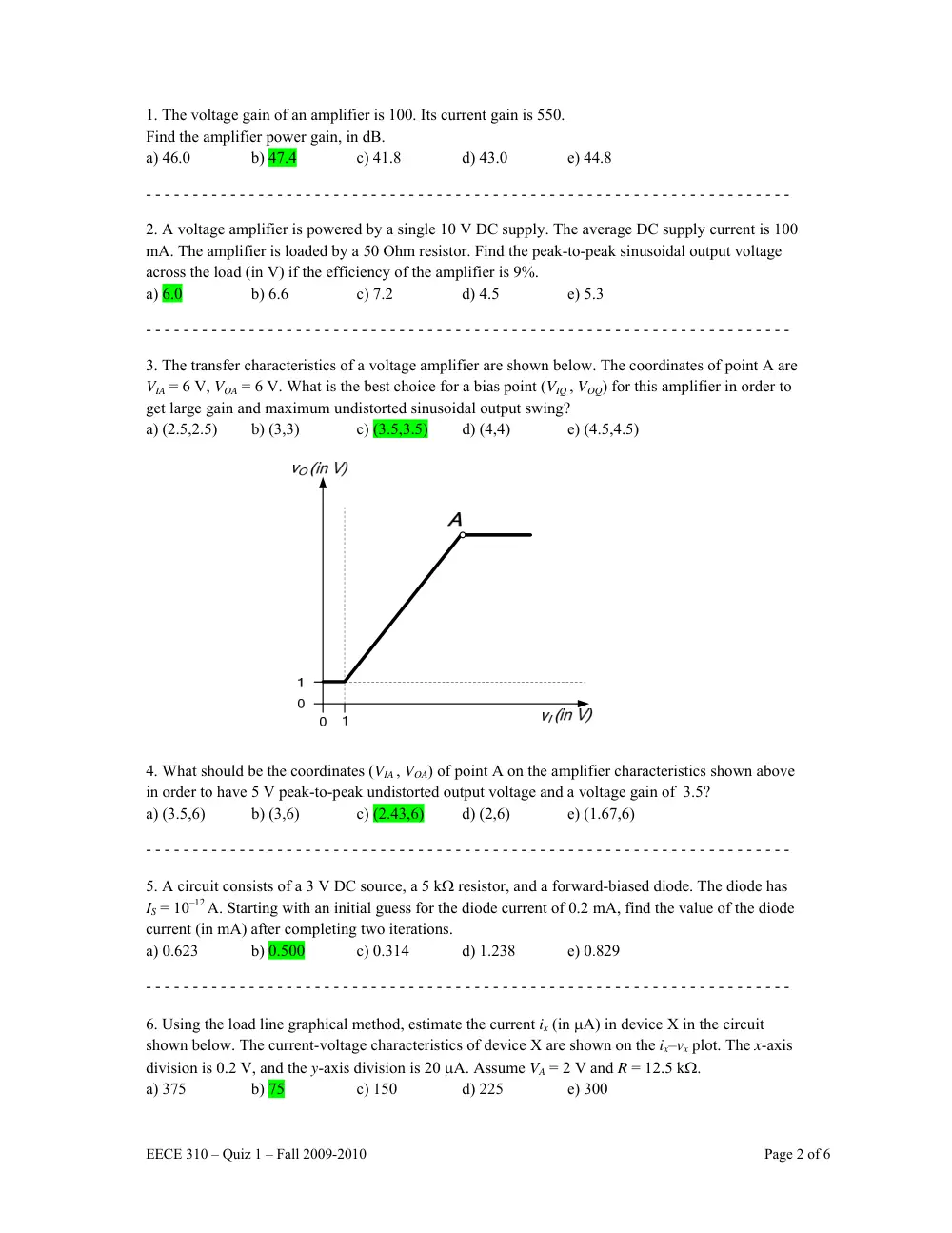
3. The transfer characteristics of a voltage amplifier are shown below. The coordinates of point A are
VIA = 6 V, VOA = 6 V. What is the best choice for a bias point (VIQ , VOQ) for this amplifier in order to
get large gain and maximum undistorted sinusoidal output swing?
a) (2.5,2.5)
b) (3,3)
c) (3.5,3.5)
d) (4,4)
e) (4.5,4.5)
4. What should be the coordinates (VIA , VOA) of point A on the amplifier characteristics shown above
in order to have 5 V peak-to-peak undistorted output voltage and a voltage gain of 3.5?
a) (3.5,6)
b) (3,6)
c) (2.43,6)
d) (2,6)
e) (1.67,6)
- - - - - - - - - - - - - - - - - - - - - - - - - - - - - - - - - - - - - - - - - - - - - - - - - - - - - - - - - - - - - - - - - - - - -
5. A circuit consists of a 3 V DC source, a 5 kΩ resistor, and a forward-biased diode. The diode has
IS = 10–12 A. Starting with an initial guess for the diode current of 0.2 mA, find the value of the diode
current (in mA) after completing two iterations.
a) 0.623
b) 0.500
c) 0.314
d) 1.238
e) 0.829
- - - - - - - - - - - - - - - - - - - - - - - - - - - - - - - - - - - - - - - - - - - - - - - - - - - - - - - - - - - - - - - - - - - - -
6. Using the load line graphical method, estimate the current ix (in μA) in device X in the circuit
shown below. The current-voltage characteristics of device X are shown on the ix–vx plot. The x-axis
division is 0.2 V, and the y-axis division is 20 μA. Assume VA = 2 V and R = 12.5 kΩ.
a) 375
b) 75
c) 150
d) 225
e) 300
EECE 310 – Quiz 1 – Fall 2009-2010
Page 3 of 6
A
R
0
0
X
- - - - - - - - - - - - - - - - - - - - - - - - - - - - - - - - - - - - - - - - - - - - - - - - - - - - - - - - - - - - - - - - - - - - -
7. The two diodes in the circuit shown below are modeled by VD0 = 0.6 V, rD = 30 Ohms, when
conducting, and by an open circuit when OFF. Determine the current in diode D2 (in mA),
when R = 500 Ohms.
a) 3.8
b) 8.2
c) 6.8
d) 5.9
e) 4.6
- - - - - - - - - - - - - - - - - - - - - - - - - - - - - - - - - - - - - - - - - - - - - - - - - - - - - - - - - - - - - - - - - - - - -
8. Find the maximum value of the output voltage vO (in V) in the circuit shown below. Assume that
the diodes are ideal, that R = 10 kΩ, and that VA = VB = 5 V. The input voltage is –10 V for 50% of
the time, and +10 V for the other 50% of the time.
a) 7
b) 6
c) 3
d) 4
e) 5
EECE 310 – Quiz 1 – Fall 2009-2010
Page 4 of 6
+
+
-
D1
D2
9. Find the average (DC) value of the output voltage (in V) in the previous problem.
a) -1.75
b) -1.5
c) -1.25
d) -1
e) -0.75
- - - - - - - - - - - - - - - - - - - - - - - - - - - - - - - - - - - - - - - - - - - - - - - - - - - - - - - - - - - - - - - - - - - - -
10. A drift current density of 5 mA/cm2 results due to the application of a 1000 V/cm electric field to
a volume of intrinsic semiconductor. Find the mobility of free electrons in the semiconductor (in
cm2/V.s), given that it is three times larger than the mobility of holes.
a) 1563
b) 938
c) 1094
d) 1250
e) 1406
11. The hole density in an N-type semiconductor is 400 cm–3. What is the type of impurity atoms?
a) Donors
b) Acceptors
c) Boron
d) Carbon
e) Silicon
12. What is the density of impurity atoms (in cm–3) in the previous problem?
a) 7.5×10¹⁷
b) 5.63×10¹⁷
c) 4.5×10¹⁷
d) 3.75×10¹⁷
e) 1.13×10¹⁸
- - - - - - - - - - - - - - - - - - - - - - - - - - - - - - - - - - - - - - - - - - - - - - - - - - - - - - - - - - - - - - - - - - - - -
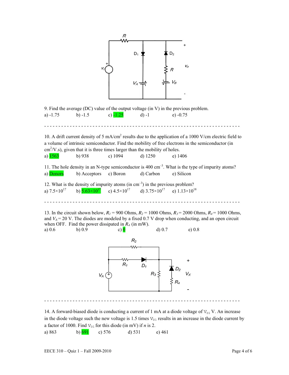
13. In the circuit shown below, R1 = 900 Ohms, R2 = 1000 Ohms, R3 = 2000 Ohms, R4 = 1000 Ohms,
and VA = 20 V. The diodes are modeled by a fixed 0.7 V drop when conducting, and an open circuit
when OFF. Find the power dissipated in R4 (in mW).
a) 0.6 b) 0.9 c) 0
d) 0.7
e) 0.8
- - - - - - - - - - - - - - - - - - - - - - - - - - - - - - - - - - - - - - - - - - - - - - - - - - - - - - - - - - - - - - - - - - - - -
14. A forward-biased diode is conducting a current of 1 mA at a diode voltage of VD1 V. An increase
in the diode voltage such the new voltage is 1.5 times VD1 results in an increase in the diode current by
a factor of 1000. Find VD1 for this diode (in mV) if n is 2.
a) 863
b) 691 c) 576
d) 531
e) 461
EECE 310 – Quiz 1 – Fall 2009-2010
Page 5 of 6
15. The same diode of the previous problem is now connected in series with a 10 kΩ resistor and a
sinusoidal voltage source with an amplitude of 3 V and zero average. Find the peak inverse voltage
(PIV) across the diode (in V).
a) 3
b) 6
c) 4
d) 2.5
e) 5
- - - - - - - - - - - - - - - - - - - - - - - - - - - - - - - - - - - - - - - - - - - - - - - - - - - - - - - - - - - - - - - - - - - - -
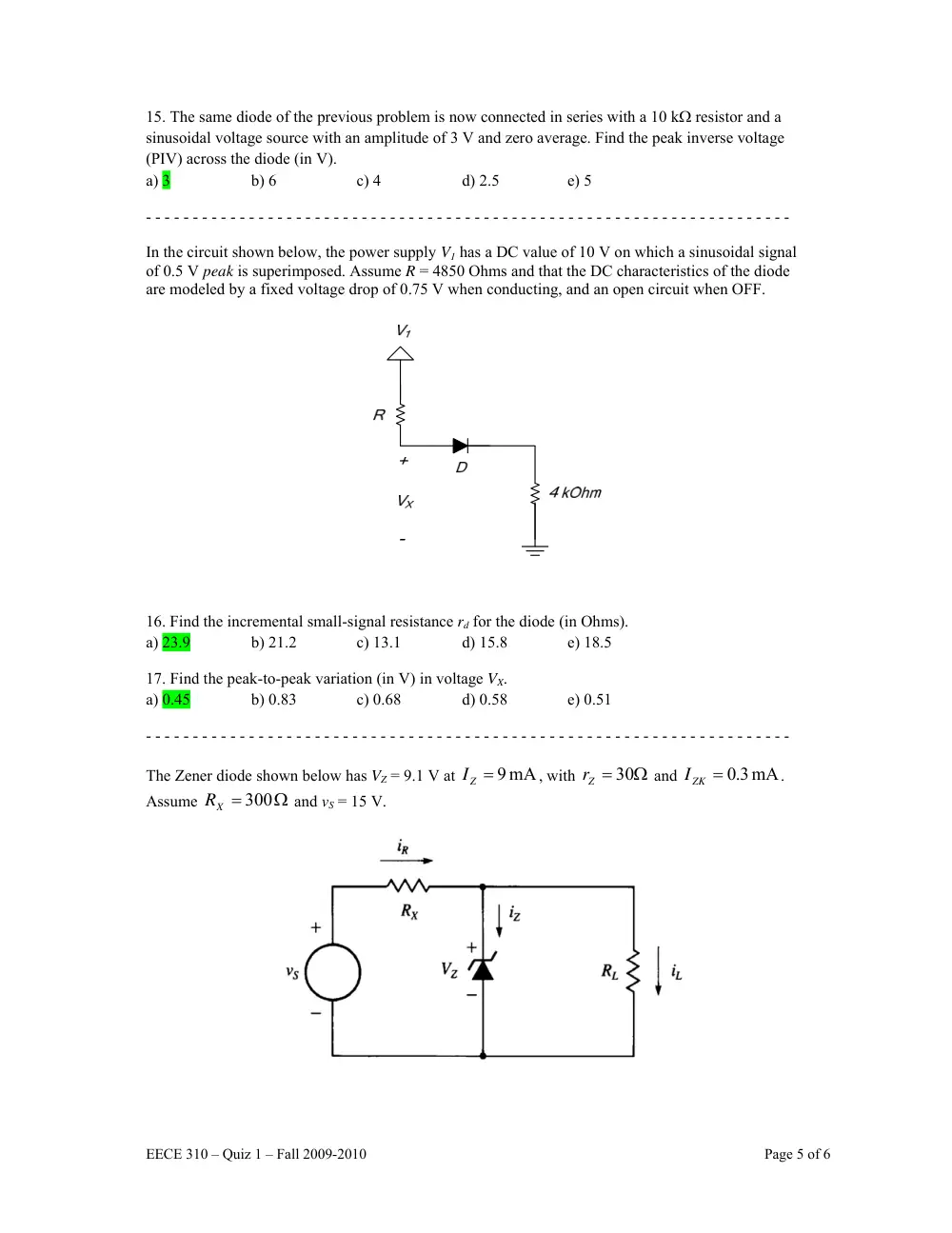
In the circuit shown below, the power supply V1 has a DC value of 10 V on which a sinusoidal signal
of 0.5 V peak is superimposed. Assume R = 4850 Ohms and that the DC characteristics of the diode
are modeled by a fixed voltage drop of 0.75 V when conducting, and an open circuit when OFF.
16. Find the incremental small-signal resistance rd for the diode (in Ohms).
a) 23.9
b) 21.2
c) 13.1
d) 15.8
e) 18.5
17. Find the peak-to-peak variation (in V) in voltage VX.
a) 0.45
b) 0.83 c) 0.68
d) 0.58
e) 0.51
- - - - - - - - - - - - - - - - - - - - - - - - - - - - - - - - - - - - - - - - - - - - - - - - - - - - - - - - - - - - - - - - - - - - -
The Zener diode shown below has VZ = 9.1 V at
9 mA
=
ZI
, with
Zr = 30Ω
and
mA
3.0
IZK =
.
Assume
Ω
=
300
RX
and vS = 15 V.
EECE 310 – Quiz 1 – Fall 2009-2010
Page 6 of 6
18. If the load consists of a fixed resistor
Ω
RL = k 1
, find the value of the Zener current Zi (in mA).
a) 13.0
b) 14.2
c) 18.1
d) 9.2
e) 10.4
19. What is the minimum value of
L
R (in Ω) for which the diode still operates in the Zener
breakdown region.
a) 288.5
b) 404.6
c) 436.8
d) 332.6
e) 254.2
- - - - - - - - - - - - - - - - - - - - - - - - - - - - - - - - - - - - - - - - - - - - - - - - - - - - - - - - - - - - - - - - - - - - -
20. A full-wave bridge rectifier circuit with a 1 kΩ load operates from a 200 V (rms) 60 Hz sinusoidal
wave supply through a 10-to-1 step-down transformer having a single secondary winding. It uses four
diodes each of which can be modeled to have a 0.7 V drop for any forward current. What is the
average (DC) voltage across the load (in V)?
a) 16.6
b) 20.2
c) 27.4
d) 34.6
e) 13.0
- - - - - - - - - - - - - - - - - - - - - - - - - - - - - - - - - - - - - - - - - - - - - - - - - - - - - - - - - - - - - - - - - - - - -
Consider a half-wave peak rectifier fed with a voltage
Sv having a triangular waveform with 10 V
peak-to-peak, zero average, and 1 kHz frequency. Assume that the diode has 0.7 V drop when
conducting. The load draws a constant current of 120 mA and the filter capacitance is C = 200 μF.
21. Find the maximum diode current (in A).
a) 6.58
b) 5.76
c) 3.30
d) 4.12
e) 4.94
22. Compute the output ripple voltage (in V).
a) 0.9
b) 0.5
c) 0.6
d) 0.7
e) 0.8