
EECE 310 Midterm, Summer 2010
American University of Beirut · Electronics · 5 pages · Prof. Ali Chehab

More EECE 310 files
- Midterm with Solutions · Fall 2014Exam · with solutionView
- Midterm · Fall 2014ExamView
- Midterm · Fall 2013ExamView
- Midterm · Fall 2012ExamView
- Midterm with Solution · Summer 2011Exam · with solutionView
- Exam 2 with Answers · Fall 2011Exam · with solutionView
- Exam 1 with Answers · Fall 2011Exam · with solutionView
- Exam 1 · Fall 2010ExamView
Show the text of this exam
EECE 310 – Midterm – Summer 2010
Page 1 of 5
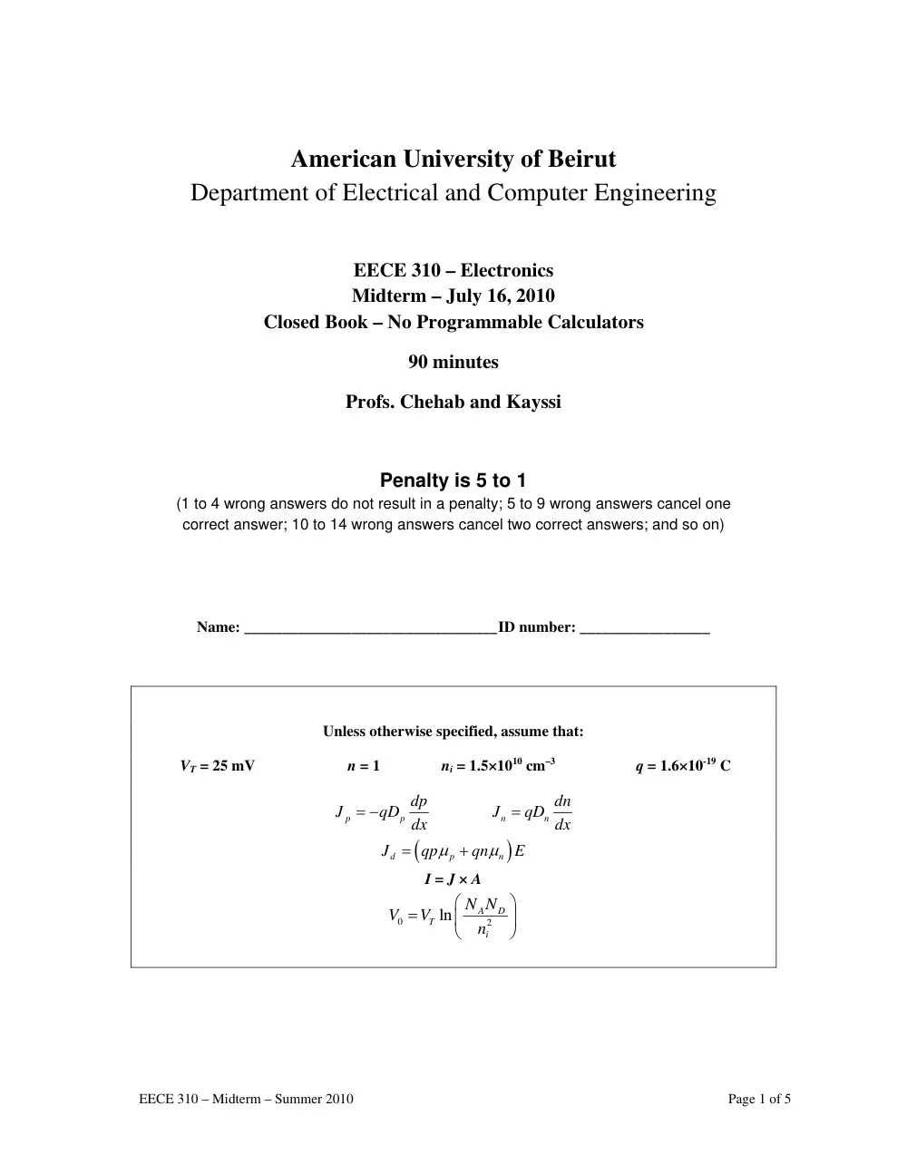
American University of Beirut
Department of Electrical and Computer Engineering
EECE 310 – Electronics
Midterm – July 16, 2010
Closed Book – No Programmable Calculators
90 minutes
Profs. Chehab and Kayssi
Penalty is 5 to 1
(1 to 4 wrong answers do not result in a penalty; 5 to 9 wrong answers cancel one
correct answer; 10 to 14 wrong answers cancel two correct answers; and so on)
Name: _________________________________ ID number: _________________
Unless otherwise specified, assume that:
VT = 25 mV n = 1 ni = 1.5×1010 cm–3 q = 1.6×10⁻¹⁹ C
p
p
dp
J
= −qD dx
n
n
dn
J
= qD dx
(
)
d
p
n
J
qp
qn
E
μ
μ
=
+
I = J × A
0
2
ln
A
D
T
i
N N
V
V
n
⎛
⎞
=
⎜
⎟
⎝
⎠
EECE 310 – Midterm – Summer 2010
Page 2 of 5
1. The voltage gain of an amplifier is 100 V/V. Its power gain is 45 dB. Find the current gain in dB.
a) 50
b) 40
c) 25
d) 45
e) 20
- - - - - - - - - - - - - - - - - - - - - - - - - - - - - - - - - - - - - - - - - - - - - - - - - - - - - - - - - - - - - - - - - - - - -
2. A voltage amplifier is powered by a single 16 V DC supply. The amplifier is loaded by a 50 Ohm
resistor and produces a peak-to-peak sinusoidal output voltage of 8 V across the load. Find the
average DC supply current (in mA) if the efficiency of the amplifier is 20%.
a) 200
b) 100
c) 250
d) 150
e) 50
- - - - - - - - - - - - - - - - - - - - - - - - - - - - - - - - - - - - - - - - - - - - - - - - - - - - - - - - - - - - - - - - - - - - -
3. A circuit consists of a 5 V DC source, a 12 kΩ resistor, and a forward-biased diode. The diode has
IS = 10–15 A and n = 1.5. Starting with an initial guess for the diode current equal to the current that
flows if the diode were ideal, find the value of the diode current (in mA) after completing two
iterations.
a) 0.386
b) 0.218
c) 0.471
d) 0.334
e) 0.417
- - - - - - - - - - - - - - - - - - - - - - - - - - - - - - - - - - - - - - - - - - - - - - - - - - - - - - - - - - - - - - - - - - - - -
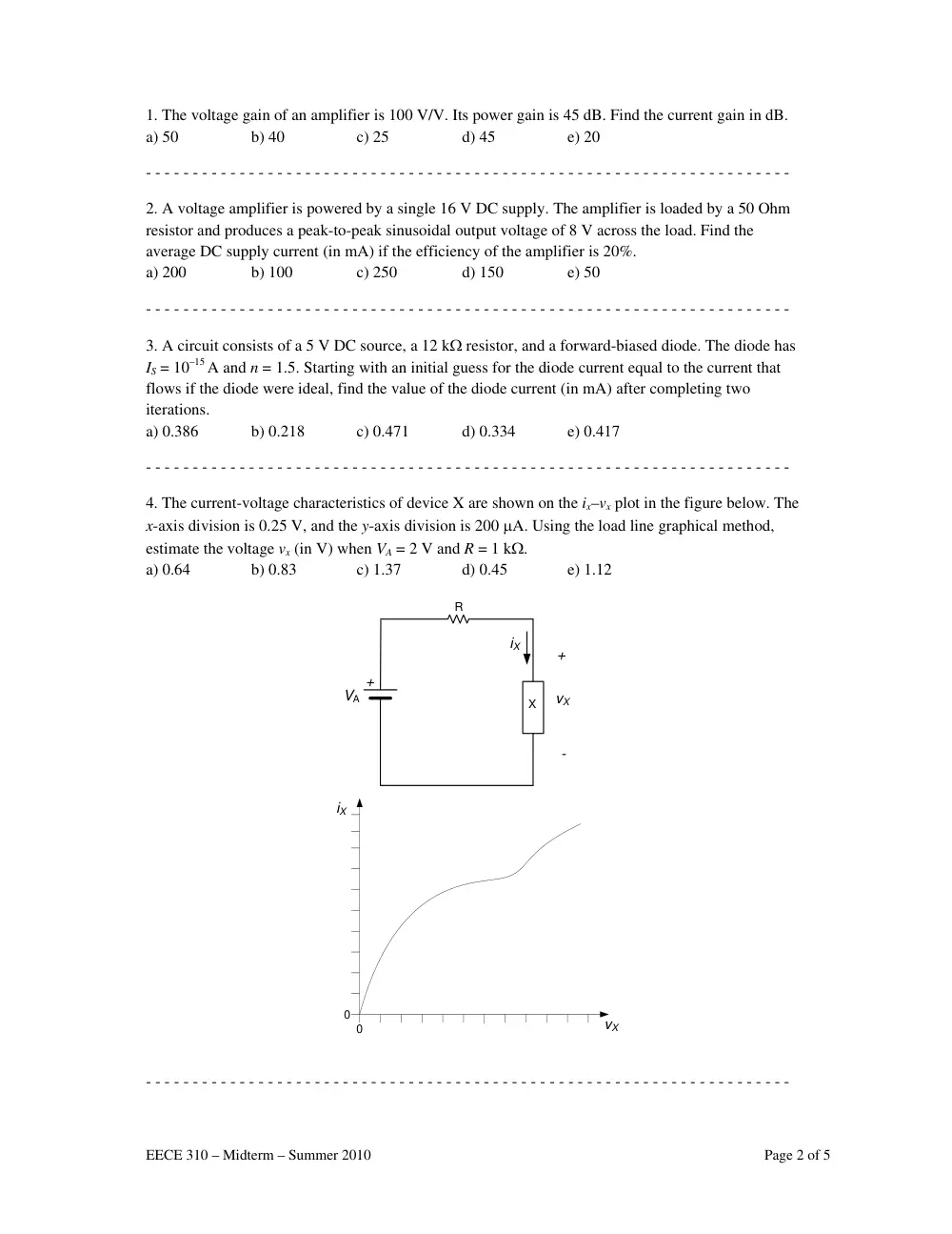
4. The current-voltage characteristics of device X are shown on the ix–vx plot in the figure below. The
x-axis division is 0.25 V, and the y-axis division is 200 μA. Using the load line graphical method,
estimate the voltage vx (in V) when VA = 2 V and R = 1 kΩ.
a) 0.64
b) 0.83
c) 1.37
d) 0.45
e) 1.12
+
+
-
vX
VA
R
iX
vX
iX
0
0
X
- - - - - - - - - - - - - - - - - - - - - - - - - - - - - - - - - - - - - - - - - - - - - - - - - - - - - - - - - - - - - - - - - - - - -
EECE 310 – Midterm – Summer 2010
Page 3 of 5
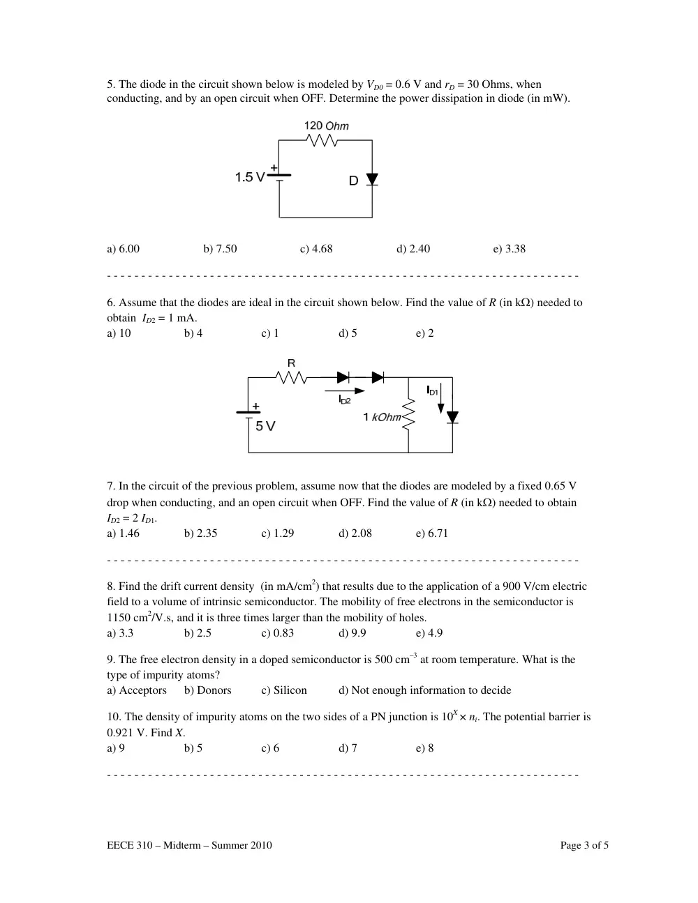
5. The diode in the circuit shown below is modeled by VD0 = 0.6 V and rD = 30 Ohms, when
conducting, and by an open circuit when OFF. Determine the power dissipation in diode (in mW).
a) 6.00
b) 7.50
c) 4.68
d) 2.40
e) 3.38
- - - - - - - - - - - - - - - - - - - - - - - - - - - - - - - - - - - - - - - - - - - - - - - - - - - - - - - - - - - - - - - - - - - - -
6. Assume that the diodes are ideal in the circuit shown below. Find the value of R (in kΩ) needed to
obtain ID2 = 1 mA.
a) 10
b) 4
c) 1
d) 5
e) 2
7. In the circuit of the previous problem, assume now that the diodes are modeled by a fixed 0.65 V
drop when conducting, and an open circuit when OFF. Find the value of R (in kΩ) needed to obtain
ID2 = 2 ID1.
a) 1.46
b) 2.35
c) 1.29
d) 2.08
e) 6.71
- - - - - - - - - - - - - - - - - - - - - - - - - - - - - - - - - - - - - - - - - - - - - - - - - - - - - - - - - - - - - - - - - - - - -
8. Find the drift current density (in mA/cm2) that results due to the application of a 900 V/cm electric
field to a volume of intrinsic semiconductor. The mobility of free electrons in the semiconductor is
1150 cm2/V.s, and it is three times larger than the mobility of holes.
a) 3.3
b) 2.5
c) 0.83
d) 9.9
e) 4.9
9. The free electron density in a doped semiconductor is 500 cm–3 at room temperature. What is the
type of impurity atoms?
a) Acceptors
b) Donors
c) Silicon
d) Not enough information to decide
10. The density of impurity atoms on the two sides of a PN junction is 10X × ni. The potential barrier is
0.921 V. Find X.
a) 9
b) 5
c) 6
d) 7
e) 8
- - - - - - - - - - - - - - - - - - - - - - - - - - - - - - - - - - - - - - - - - - - - - - - - - - - - - - - - - - - - - - - - - - - - -
EECE 310 – Midterm – Summer 2010
Page 4 of 5
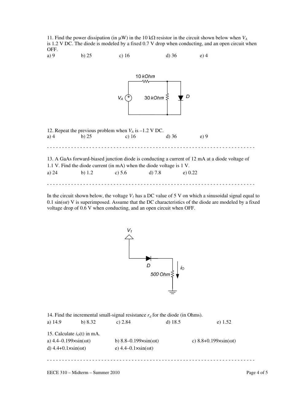
11. Find the power dissipation (in μW) in the 10 kΩ resistor in the circuit shown below when VA
is 1.2 V DC. The diode is modeled by a fixed 0.7 V drop when conducting, and an open circuit when
OFF.
a) 9
b) 25 c) 16
d) 36
e) 4
12. Repeat the previous problem when VA is –1.2 V DC.
a) 4
b) 25
c) 16
d) 36
e) 9
- - - - - - - - - - - - - - - - - - - - - - - - - - - - - - - - - - - - - - - - - - - - - - - - - - - - - - - - - - - - - - - - - - - - -
13. A GaAs forward-biased junction diode is conducting a current of 12 mA at a diode voltage of
1.1 V. Find the diode current (in mA) when the diode voltage is 1 V.
a) 24
b) 1.2
c) 5.6
d) 7.8
e) 0.22
- - - - - - - - - - - - - - - - - - - - - - - - - - - - - - - - - - - - - - - - - - - - - - - - - - - - - - - - - - - - - - - - - - - - -
In the circuit shown below, the voltage V1 has a DC value of 5 V on which a sinusoidal signal equal to
0.1 sin(ωt) V is superimposed. Assume that the DC characteristics of the diode are modeled by a fixed
voltage drop of 0.6 V when conducting, and an open circuit when OFF.
14. Find the incremental small-signal resistance rd for the diode (in Ohms).
a) 14.9
b) 8.32
c) 2.84
d) 18.5
e) 1.52
15. Calculate iO(t) in mA.
a) 4.4–0.199×sin(ωt)
b) 8.8–0.199×sin(ωt)
c) 8.8+0.199×sin(ωt)
d) 4.4+0.1×sin(ωt)
e) 4.4–0.1×sin(ωt)
- - - - - - - - - - - - - - - - - - - - - - - - - - - - - - - - - - - - - - - - - - - - - - - - - - - - - - - - - - - - - - - - - - - - -
EECE 31
The Zen
vS is 20 V
from 0 t
16. Find
conditio
a) 81
17. For t
Zener vo
a) 0.34
- - - - - -
18. A fu
supply th
transform
modeled
resistor
a) 9.21
- - - - - -
The diod
remain c
drop bel
solutions
19. Find
a) 521
20. Find
a) 33.6
10 – Midterm
ner diode sho
V, but varies
o 20 mA.
d the largest v
ons.
b) 1
the value of R
oltage VZ (in
b) 0
- - - - - - - -
ull-wave recti
hrough step-
mer turns rat
d by a 0.75 V
(in mA)?
b) 8
- - - - - - - -
de in the circ
conducting w
low 2 mA, an
s are possibl
d the value of
b) 4
d the value of
b) 1
– Summer 20
own below ha
s by +/ –25%
value of RX (
52
RX calculated
V)?
.27
- - - - - - - - -
ifier circuit w
-down transfo
tio for each s
V drop for an
.31
- - - - - - - - -
cuit shown be
when VA varie
nd the power
le]
f R1 (in Ω).
07
f R2 (in Ω).
8.9
010
as VZ = 10 V
%, i.e. betwee
(in Ω) that en
c) 267
d in the prev
c) 0.56
- - - - - - - - -
with a 3 kΩ l
former having
secondary is
ny forward cu
c) 4.91
- - - - - - - - -
elow drops a
es between 5
r dissipation
+
VA
c) 372
c) 81.7
V at IZ = 25 m
en 15 V and 2
nsures Zener
d) 204
vious problem
d) 0.11
- - - - - - - - -
load operates
g two second
15-to-1. The
urrent. What
d) 4.15
- - - - - - - - -
a constant 0.7
5 V and 10 V
of the diode
R1
R2
d) 233
d) 24.4
mA, with rZ =
25 V. The lo
region opera
e) 5
m, what is the
e) 0
- - - - - - - - -
s from a 311
dary winding
e rectifier use
is the averag
e) 2
- - - - - - - - -
7 V when co
V. Moreover,
should not e
D
e) 3
e) 6
= 5 Ω and IZK
oad draws a c
ation for the
33
e maximum
0.01
- - - - - - - - -
V (peak) 50
gs and a cent
es two diode
ge (DC) curr
.51
- - - - - - - - -
onducting. Th
the diode cu
exceed 10 m
11
67.2
K = 5 mA. Th
current that v
diode under
variation in t
- - - - - - - - -
0 Hz sinusoid
ter tap. The
s each of wh
rent in the loa
- - - - - - - - -
he diode shou
urrent should
W. [Note: m
Page 5 of 5
he source
varies
r all
the
- - - - -
dal wave
hich is
ad
- - - - -
uld
d not
multiple
5