
EECE 311 Lecture 2, Spring 2012
American University of Beirut · Electronic Circuits · 52 pages


Showing the first 10 of 52 pages. Download the PDF to see all of it.
More EECE 311 files
Show the text of this lab
EECE 311: Electronic Circuits
Part 2
AMPLIFIER FREQUENCY
RESPONSE
2
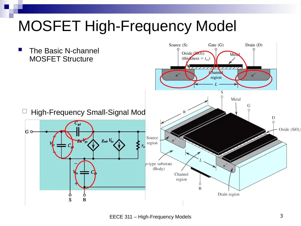
High-Frequency Small-Signal Model
EECE 311 – High-Frequency Models
3
MOSFET High-Frequency Model
The Basic N-channel
MOSFET Structure
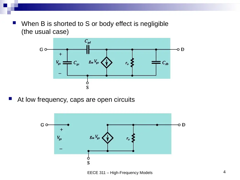
When B is shorted to S or body effect is negligible
(the usual case)
EECE 311 – High-Frequency Models
4
At low frequency, caps are open circuits
High-Frequency Small-Signal Model
EECE 311 – High-Frequency Models
5
BJT High-Frequency Model
B’ is the internal base
rx is base spreading resistance B-B’ (small, negligible at low frequency)
Vp = Vb’e
EECE 311 – High-Frequency Models
6
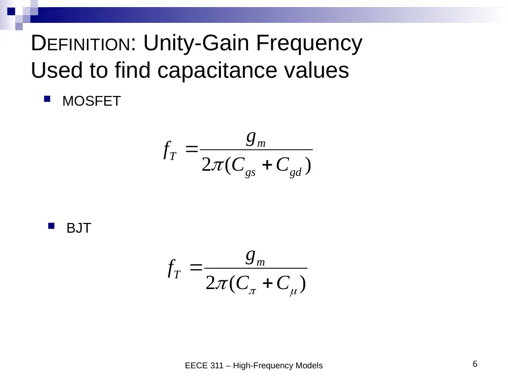
DEFINITION: Unity-Gain Frequency
Used to find capacitance values
2 (
)
m
T
gs
gd
g
f
C
C
MOSFET
BJT
2 (
)
m
T
g
f
C
C
Frequency Response
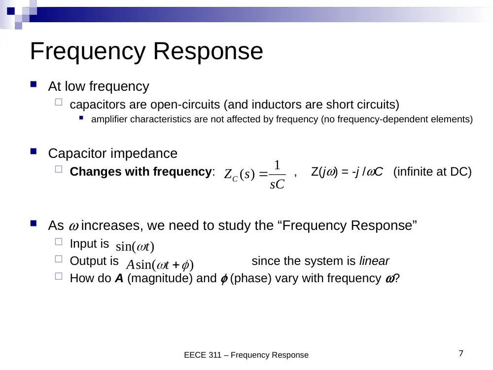
At low frequency
capacitors are open-circuits (and inductors are short circuits)
amplifier characteristics are not affected by frequency (no frequency-dependent elements)
Capacitor impedance
Changes with frequency: , Z(jw) = -j /wC (infinite at DC)
As w increases, we need to study the “Frequency Response”
Input is
Output is
since the system is linear
How do A (magnitude) and f (phase) vary with frequency w?
EECE 311 – Frequency Response
7
1
ZC ( )
s
sC
sin(
)t
sin(
)
A
t
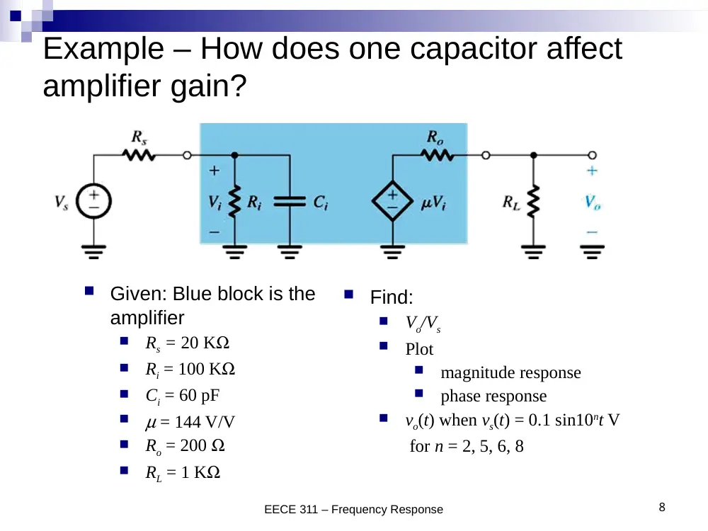
Example – How does one capacitor affect
amplifier gain?
EECE 311 – Frequency Response
8
Given: Blue block is the
amplifier
Rs = 20 KW
Ri = 100 KW
Ci = 60 pF
m = 144 V/V
Ro = 200 W
RL = 1 KW
Find:
Vo/Vs
Plot
magnitude response
phase response
vo(t) when vs(t) = 0.1 sin10nt V
for n = 2, 5, 6, 8
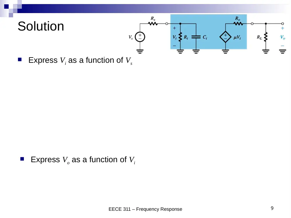
Solution
EECE 311 – Frequency Response
9
i
i
s
i
s
Z
V
V Z
R
Express Vi as a function of Vs
1
1
1
1
1
(
)
i
i
i
s
s
s
i
s
s
i
s
i
R
Z
V
V
V
V
Z
R
R Y
R
sC
1
1
1
1
(
//
)
s
i
i
i
R
R
s
s
i
i
s
i
s
i
V
R
V
sR C
R
R
sC R
R
Express Vo as a function of Vi
o
L
L
o
i
L
o
i
L
o
V
R
R
V
V R
R
V
R
R
Solution
EECE 311 – Frequency Response
10
1
1
(
//
)
o
i
L
s
L
o
i
s
i
s
i
V
R
R
V
R
R
R
R
sC R
R
0
( )
1
/
o
s
V
K
T s
V
s
This is of the form:
K
1/w0
Low-pass single-time-constant (LP-STC)
K is the low-frequency gain
w0 is the 3-dB frequency
1000
100K
144
100
1000
200
100K
20K
i
L
L
o
i
s
R
R
K
R
R
R
R
6
0
12
3
1
1
10 rad/sec
(
//
)
60 10
(100//20) 10
i
i
s
C R
R
Review: Low-Pass Single Time Constant
Gain (or Transfer) function:
Low-frequency gain = K
Upper 3-dB frequency = w0
-20 dB/decade drop at high frequency (w >> w0)
What is T at w0?
11
0
( )
1
/
o
s
V
K
T s
V
s
Solution (continued)
EECE 311 – Frequency Response
12
Bode Plot - Magnitude
Solution
EECE 311 – Frequency Response
13
Bode Plot - Phase
Solution
EECE 311 – Frequency Response
14
Output voltage vo(t) when
vs(t) = 0.1 sin102t V
vs(t) = 0.1 sin105t V
vs(t) = 0.1 sin106t V
vs(t) = 0.1 sin108t V
For w = 102 rad/sec: vo(t) = 10 sin(102t) V
For w = 105 rad/sec: vo(t) = 9.95 sin(105t – 5.7o) V
For w = 106 rad/sec: vo(t) = 7.07 sin(106t – 45o) V
For w = 108 rad/sec: vo(t) = 0.1 sin(108t – 89.4o) V
6
6
6
2
6
6
2
100
100
(
)
arctan(
/10 )
1
/10
1 (
/10 )
100
( )
0.1
sin(
arctan(
/10 ))
1 (
/10 )
o
T j
j
v t
t
15
Amplifier High-Frequency Response
We will not consider low-frequency effects
In IC amplifiers, neither bypass nor coupling capacitors are used
because of their large size: Amplifiers are directly coupled.
Bode Plot
16
0
1
2
1
2
1
2
1
2
( )
( )
( )
1
lim
1
1
... 1
( )
1
1
... 1
,
...
are the zero frequencies and can be positive, negative or infinite.
,
.
M
H
H
s
Z
Z
Zn
H
P
P
Pn
Z
Z
Zn
P
P
A s
A
F
s
F
s
s
s
s
F
s
s
s
s
..
Pn are the pole frequencies and are positive and real.
The High-Frequency Gain Function
17
The Dominant Pole Approximation
H
2
2
2
2
1
2
1
2
1
1
1
1
1
...
2
...
P
P
Z
Z
Better Approximation
If one pole is obviously smaller than the other zeroes and poles.
wp1 is 2 octaves down
(less by a factor of 4)
18
2
2
1
2
2
2
1
2
2
2
2
2
2
2
1
2
1
1
(
)
2
1
. 1
...
1
2
1
. 1
...
let
1
1
... 1
2 1
... 1
H
H
H
H
Z
Z
H
H
P
P
H
P
P
Pn
Z
Zn
F
j
x
x
x
x
x
x
The Exact Solution: Solve |A|=|AM|/√2
ωH = √x
19
Example: Find
H
5
4
4
1 10
( )
1
1
10
4 10
H
s
F
s
s
s
5
1
2
4
1
4
2
10 rad/sec
10 rad/sec
4 10 rad/sec
Z
Z
P
P
Given:
Solution:
Dominant Pole?
4
10 rad/sec
H
Better Approximation:
H
2
2
2
2
1
2
1
2
1
1
1
1
1
2
9800 rad/sec
P
P
Z
Z
Exact Solution:
2
2
2
1
2
1
1
1
2 1
9573 rad/sec
P
P
Z
H
x
x
x
x
20
Example: Magnitude Bode Plot
5
4
4
1 10
( )
1
1
10
4 10
H
s
F
s
s
s
Given:
Pole:
slope
20 dB/decade
Zero:
slope
20 dB/decade
Bode Plot Construction
21
5
4
4
1 10
( )
1
1
10
4 10
H
s
F
s
s
s
P
P
Z
Bode Plot Construction
22
5
4
4
1 10
( )
1
1
10
4 10
H
s
F
s
s
s
What is the slope?
Bode Plot Construction
23
5
4
4
1 10
( )
1
1
10
4 10
H
s
F
s
s
s
What is the slope?
What is this value (dB)?
Bode Plot Construction
24
5
4
4
1 10
( )
1
1
10
4 10
H
s
F
s
s
s
What is the slope?
What is this value (dB)?
25
High-Frequency Response of
Common Source and Common Emitter Amplifiers
vsig
Rsig
VDD
vI
Q1
vO
Q2
VBIAS
Rsig
vsig
VDD
Q1
vO
Q2
VBIAS
Cdb2
Cdb1
Cgd2
Cgs2
Cgs1
Cgd1
26
At signal frequencies
Rsig
vsig
Q1
vO
Q2
Cdb2
Cdb1
Cgd2
Cgs2
Cgs1
Cgd1
27
High-Frequency Response of
Common Source and Common Emitter Amplifiers
High-Frequency Small-Signal Equivalent Circuits
CS:
CE:
RL represents the output resistance of the active load and any load resistance
CL represents the total capacitance between drain (or collector) and ground. It also
includes the input capacitance of a succeeding amplifier stage, and parasitic/load
capacitances.
We will analyze the CS circuit only since the analysis of the CE amplifier is exactly
the same after relabeling
28
to
,
to
,
to
gs
gd
gs
C
C
C
C V
V
'
'
//
sig
sig
sig
x
sig
x
sig
r
V
V
r
R
r
R
r
R
r
and replacing
and
by:
sig
sig
V
R
Thevenin equivalent
for circuit composed
of Vsig, Rsig, rx, and rp
29
Common Source / Common-Emitter High-Frequency
Small-Signal Equivalent Circuits
Rsig
vsig
Q1
vO
Q2
Cdb2
Cdb1
Cgd2
Cgs2
Cgs1
Cgd1
30
Exact Analysis in s-domain: YC = sC
'
'
'
KCL at drain:
KVL at input:
0
KCL at gate:
o
gd
gs
o
m
gs
L
o
L
sig
sig
i
gs
i
gs
gs
gd
gs
o
V
sC
V
V
g V
sC V
R
V
R I
V
I
sC V
sC
V
V
'
'
'
'
'
2
'
'
'
2
1
2
1
2
1
1
1
1
1
1
1
1
1
1
gd
m
L
m
o
sig
gs
gd
m
L
sig
L
gd
L
L
gd
gs
L
gd
sig
L
M
M
Z
Z
o
m
Z
sig
gd
P
P
P
C
g R
s g
V
V
s
C
C
g R
R
C
C
R
s
C
C
C
C C
R R
s
s
A
A
V
g
V
b s
b s
C
s
s
s
2
2
1
2
1
2
1
'
'
'
'
'
'
2
'
'
1
1
1
1
1
1
1
1
P
P
P
P
P
P
gs
gd
m
L
sig
L
gd
L
gs
gd
m
L
sig
L
gd
L
P
L
gd
gs
L
gd
sig
L
s
s
s
C
C
g R
R
C
C
R
C
C
g R
R
C
C
R
C
C
C
C C
R R
1
2
negligible (
0) if
P
P
31
• Low frequency
gain is –gmR’L
• Zero frequency
gm/Cgd is very
high
• What is the 3-dB
frequency?
32
Miller’s Theorem
When Z is a capacitor C
C1 = C (1 – K)
C2 = C (1 – 1/K)
33
Example 2: Find
/
and
.
o
sig
H
V
V
Given:
Solution using Miller
1 pF
Z
K 100
100
o
i
V
V
1
1
1
9
1
1
1
1
1
1
10 k
101 p
100
100
1
(1010 n)
1
10
157.6 kHz
1010
2
i
sig
sig
sig
i
sig
o
m
o
i
sig
H
H
H
H
V
sC
V
sC R
R
sC
V
V
s
V
A
V
V
s
V
s
f
1
2
101pF
1.01pF
C
C
34
Find using Miller’s Theorem
H
35
Miller’s Approximation in CS/CE
'
1
in
gs
gd
m
L
C
C
C
g R
'
At midband,
o
m
L
gs
V
K
g R
V
The input circuit and the output circuit are low-pass
RC circuits
What is the pole frequency for a simple RC circuit?
+CL
36
Miller’s Approximation in CS/CE
'
'
'
1
1
1
H
sig
in
sig
gs
gd
m
L
R C
R
C
C
g R
'
1
o
m
m
m
L
sig
H
V
A
A
g R
s
V
Input circuit pole at 1/(R’sig Cin)
Output circuit pole at 1/(R’L Cout)
Usually input circuit determines high frequency response
+CL
37
Miller’s Approximation in CS/CE
Input circuit pole at win = 1/(R’sig Cin)
Output circuit pole at wout = 1/(R’L Cout)
2
2
1
1
1
in
out
H
If input pole is not much smaller than output pole
+CL
38
Open-Circuit Time Constants
Instead of finding A(s) to get wH, we’d like to determine wH directly from
the circuit
1
H
i
io
i
C R
is capacitor " " in the circuit.
is the resistance seen by capacitor
with all other capacitors open-circuited
and the signal sources set to zero.
open-circuit time constant
i
io
i
i
io
i
C
i
R
C
R C
1
1
2
2
H
i
io
i
i
i
f
C R
39
Find using OCTC
H
'
'
gs : find
gs
sig
gs
gs
gs
gs
sig
C
R
R
C R
C R
40
'
1
1
'
'
1
'
'
1
: find
'
'
'
'
'
'
gd
gd
gs
x
sig
gs
x
o
x
m
gs
m
gs
L
L
x
gd
sig
L
m
sig
L
x
gd
gd
gd
gd
sig
L
m
sig
L
C
R
V
I R
V
V
V
I
g V
g V
R
R
V
R
R
R
g R R
I
C R
C
R
R
g R R
Frequently-used resistance calculation
41
RX
RY
gmVX
VX
+
-
RXY
(1
)
where
(1
)
where
XY
X
Y
m
X
Y
XY
Y
X
Y
Y
m
Y
XY
X
Y
X
X
m
X
R
R
R
g R R
R
R
R
g R
R
R
R
g R
42
Find using OCTC (cont’d)
H
L : find
CL
C
R
9
1
10
rad/sec
80 1000
1080
H
43
Open-Circuit Time Constants (cont’d)
'
'
'
'
'
'
gs
gs
sig
gd
gd
sig
L
m
sig
L
L
CL
L
C
R
R
C
R
R
R
g R
R
C
R
R
gs
gs
gs
gd
gd
gd
cl
L
CL
C R
C R
C R
1
H
gs
gd
cl
Numberical Example: Find
H .
1 pF
1pF
gs
gd
C
C
80 k
neglect
1000 k
gs
L
gd
R
C
R
Given:
Solution:
80 ns
1000 ns
gs
gs
gs
gd
gd
gd
C R
C R
OCTC allows us to
determine the circuit
component(s) that
limit the value of wH
'
'
'
'
'
'
L
gs
gd
C
gs
sig
gd
sig
L
m
sig
L
L
L
C R
C
R
R
g R
R
C R
44
Open-Circuit Time Constants (cont’d)
'
'
'
1
'
'
'
H
gs
sig
gd
sig
L
m
sig
L
L
L
C R
C
R
R
g R
R
C R
'
1
o
m
m
m
L
sig
H
V
A
A
g R
s
V
45
Example 1: CMOS Common-Source Amp
'
2
'
2
Given
3V
200 A/V
65 A/V
10 for all MOSFETs
0.6V
20V
10V
100 A
DD
n
p
W
L
tn
tp
An
Ap
REF
V
k
k
V
V
V
V
I
Find fH using:
Miller’s approximation
Open-circuit time constants (OCTC)
Transfer function
Given
50 k
30 fF
10 fF
50 fF
sig
gs
gd
L
R
C
C
C
'
1
'
1
Miller's approximation
input pole frequency:
(1
)
30
43.2 10
462 fF
1
6.89 MHz
2
'
output pole frequency:
1
1
1
10 1
50
60.24 fF
42.2
1
39
2
'
in
gs
m
L
gd
in
in
sig
out
gd
L
m
L
out
out
L
C
C
g R C
f
C R
C
C
C
g R
f
C
R
.6 MHz
input pole is dominant:
6.89 MHz
Hf
46
Example 1: CMOS Common-Source Amp
1
'
1
2
Given:
50 k
'
here
30 fF
10 fF
50 fF
Previously found:
0.633 mA/V
//
66.67 K
sig
sig
gs
gd
L
m
L
o
o
R
R
C
C
C
g
R
r
r
47
Example 1: CMOS Common-Source Amp
1
'
1
2
Given:
50 k
30 fF
10 fF
50 fF
Previously found:
0.633 mA/V
//
66.67 K
sig
gs
gd
L
m
L
o
o
R
C
C
C
g
R
r
r
'
'
1
'
OCTC
'
50k
'
(1
)
50 43.2
66.67
2226.67k
66.67k
30 50 10 2226.67
50 66.67
1500
22266.7
3333.3
1
5.87 MHz
2
L
L
gs
sig
gd
sig
m
L
L
C
L
H
gs
gs
gd
gd
L
C
H
H
R
R
R
R
g R
R
R
R
C R
C R
C R
f
48
Example 1: CMOS Common-Source Amp
1
'
1
2
Given:
50 k
30 fF
10 fF
50 fF
Previously found:
0.633 mA/V
//
66.67 K
sig
gs
gd
L
m
L
o
o
R
C
C
C
g
R
r
r
1
2
1
1
Exact values (from transfer function)
10.1 GHz,
5.96 MHz, and
386 MHz
is a
dominant pole
5.96 MHz
Error in Miller's approximation = +15.6%
Error in OCTC approximation =
1.51%
z
p
p
p
H
p
f
f
f
f
very
f
f
Example 2: CMOS Common-Source Cascade
What is the overall low-frequency gain if the per-stage gain is –42?
What is the 3-dB frequency if the per-stage 3-dB fH is 6 MHz?
Solution
50
Example 3: Common-Emitter Amplifier
Find the 3-dB frequency
fH using Miller’s approximation
Assume that the input circuit
determines the value of fH
51
vi
Q3
IREF
Q2
Q1
vo
VCC
Rsig
vsig
Solution
52