
EECE 311 Lecture 7, Spring 2012
American University of Beirut · Electronic Circuits · 29 pages




Showing the first 10 of 29 pages. Download the PDF to see all of it.
More EECE 311 files
Show the text of this lab
EECE 311: Electronic Circuits
Part 7
2
Stability in Feedback Amplifiers
1
f
A s
A
s
s A s
180
1
0
.
:
180
j
s A s
L s
A s
s
L j
A j
j
A j
j
e
L j
at
Characteristic equation:
Loop gain:
When does loop gain become equal to –1?
check |L| at w180
3
Effect of Feedback on Amplifier Poles
Single Pole Amplifier
1
Assuming is independent of frequency:
1
1
1
1
o
p
o
o
f
p
o
Pf
p
o
A
A s
s
A
A
A
s
s
A
A
Bandwidth Extended
Gain Decreased
Feedback did not affect
stability
4
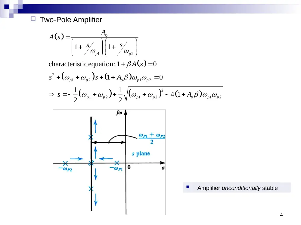
Two-Pole Amplifier
1
2
2
1
2
1
2
2
1
2
1
2
1
2
1
1
characteristicequation: 1
0
1
0
1
1
4 1
2
2
o
p
p
p
p
o
p
p
p
p
p
p
o
p
p
A
A s
s
s
A s
s
s
A
s
A
Amplifier unconditionally stable
5
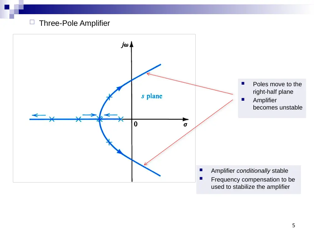
Three-Pole Amplifier
Amplifier conditionally stable
Frequency compensation to be
used to stabilize the amplifier
Poles move to the
right-half plane
Amplifier
becomes unstable
6
Stability Study Using Bode Plots of Loop Gain
Bode plot of
:
A
For stability, make
sure that
w1 < w180
Typically, we want:
GM = 30 dB and
PM = 60º
7
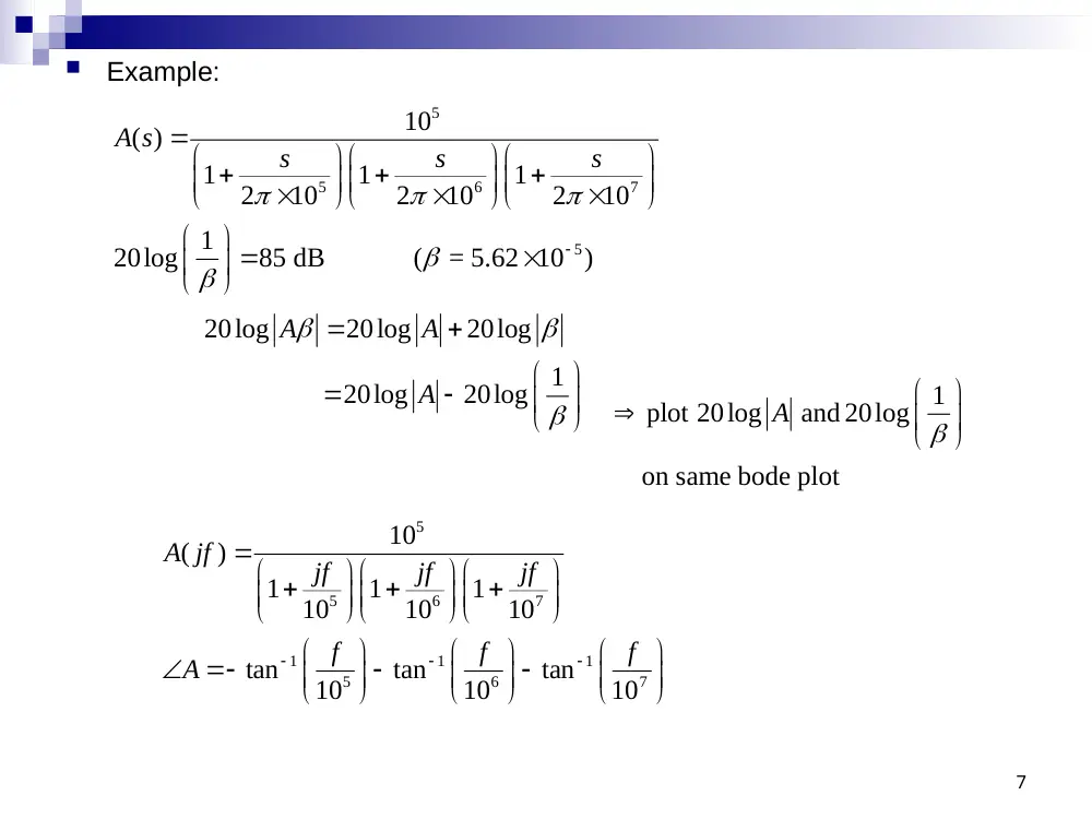
Example:
5
5
6
7
5
10
( )
1
1
1
2
10
2
10
2
10
1
20log
85 dB ( = 5.62 10 )
A s
s
s
s
20log
20log
20log
1
20log
20log
A
A
A
1
plot 20log
and 20log
on same bode plot
A
5
5
6
7
1
1
1
5
6
7
10
(
)
1
1
1
10
10
10
tan
tan
tan
10
10
10
A jf
jf
jf
jf
f
f
f
A
8
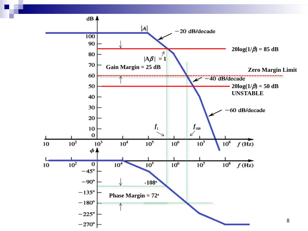
20log(1/b) = 85 dB
|Ab | = 1
-108o
Phase Margin = 72o
f180
Gain Margin = 25 dB
Zero Margin Limit
20log(1/b) = 50 dB
UNSTABLE
f1
9
10
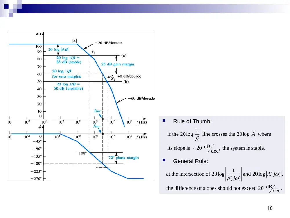
Rule of Thumb:
General Rule:
if the 20log 1
line crosses the 20log
where
dB
its slope is
20
, the system is stable.
dec
A
1
at the intersection of 20log
and 20log
(
) ,
(
)
the difference of slopes should not exceed 20 dB
.
dec
A j
j
Example: Stabilize amplifier for b = 0.01
11
New pole
frequency
Example: Stabilize amplifier for b = 0.01
12
Shift first
pole to here
13
Frequency Compensation
Gain curve A intersects the
20 log (1/β) line on the
-40 dB/dec line.
Option 1:
add a low frequency pole (A’)
Option 2:
shift dominant pole to a lower
frequency (A’’)
14
Pole Shifting
Pole shifting is done by introducing a capacitor between B and B’.
Therefore shifting the pole from
1
1
1
to
2
2
p
x
x
x
x
C
f
R C
R
C
C
One problem with this scheme is that the CC capacitor is often too large to be
implemented on integrated circuits.
15
Miller Compensation and Pole Splitting
Introduce a compensating capacitor, Cf, in the feedback path of the amplifier stage
1
2
1
1
2
2
1
2
2
1
1
2
2
1
2
1
2
1
2
1
2
1
2
without
:
1
1
2
2
with
,transfer function becomes :
1
f
p
p
f
f
m
o
i
f
m
f
C
f
f
R C
R C
C
sC
g
R R
V
I
s C R
C R
C
g R R
R
R
s
C C
C
C
C
R R
16
1
2
2
1
1
2
2
1
2
1
2
1
2
1
2
1
2
2
'
'
'
'
'
'
1
2
1
2
1
2
'
1
'
1
1
1
1
( )
1
1
1
normally, one of the poles, say
, is dominant
( )
1
f
m
o
i
f
m
f
p
p
p
p
p
p
p
p
sC
g
R R
V
I
s C R
C R
C
g R R
R
R
s
C C
C
C
C
R R
s
s
s
D s
s
s
D s
2
'
'
1
2
1
1
1
2
2
1
2
1
2
2
1
2
1
2
1
2
2
p
p
p
f
m
m
f
p
f
s
f
C R
C R
C
g R R
R
R
g C
f
C C
C
C
C
Miller Compensation therefore shifts the
dominant pole to the left while at the same
time shifting the second pole further to the
right (Pole Splitting).
Also, the compensating capacitor is
multiplied by gmR2 and allows us to use
much smaller on-chip capacitors.
17
Example
1
2
1
2
1 pF
0.3 pF
0.2 pF
50 K
1 mA/V
C
m
C
C
C
R
R
g
1
2
without
:
3.2 MHz
10.6 MHz
C
p
p
C
f
f
'
1
'
2
with
:
0.3 MHz
57 MHz
800 MHz
2
C
p
p
m
z
C
C
f
f
g
f
C
18
The Two-Stage CMOS OP-AMP
19
High Frequency Model
1
1
2
2
2
2
2
2
1
2
2
2
p
m
C
m
p
m
Z
C
f
R G
R C
G
f
C
G
f
C
1
1
1
2
2
2
1
2
2
should be less than
and less than
m
t
p
C
t
z
m
m
C
p
m
m
G
f
A f
C
f
f
G
G
C
C
f
G
G
to let the gain curve intersect with the
0 dB-line (feedback with b = 1) with a
slope of -20 dB/dec.
Considering feedback with b = 1
20
Positive Feedback
For positive feedback: Af = A / (1 – b A)
Barkhausen criterion for oscillation
b A = 1
(j) A(j) = 1
magnitude(b A) = 1
phase angle(b A) = 0
Sinusoidal Oscillators
Wien-Bridge Oscillator
Amplifier gain
Feedback factor
21
1
f
r
R
A
R
0
0
2
0
0
//
1
1
//
1/
1
(1
)
(1
)
/
1
/
3
/
1
P
S
P
R
R sC
Z
sRC
R
Z
Z
R sC
R
sC
R
sRC
sC
sRC
sRC
sRC
sRC
sRC
s
RC
s
s
Sinusoidal Oscillators
Wien-Bridge Oscillator
Oscillation condition:
Pure real:
At oscillation
frequency:
22
0
2
0
0
0
2
0
0
(
) (
)
1
1
/
/
1
/
3
/
1
1
/
/
1
3
/
1
/
f
r
f
r
A j
j
R
R
j
j
j
j
R
R
j
2
0
0
1
1
/
0
RC
(
) (
)
1
/
1
2
3
f
r
f
r
A j
j
R
R
R
R
Sinusoidal Oscillators
Phase-shift oscillator
Amplifier phase shift = 180 degrees
Inverting OP-AMP amplifier
The other 180 degrees come from the three RC
sections
Feedback block
23
Sinusoidal LC Oscillators
Feedback block is a tuned LC circuit
24
C2
C1
L
L2
L1
C
LC Oscillators
Colpitts Oscillator
Amplifier assumed to have
infinite input resistance
25
Colpitts Oscillator
KCL at output node
LC2 voltage divider
Therefore
26
1
2
1
( )
( )
( )
0
m
i
o
f
G V s
sC
V s
sC V
s
R
2
2
1
( )
( )
1
f
o
V
s
s LC V s
2
2
1
2
1
1
( )
1
( )
i
f
m
V s
sC
sC
s LC
V
s
G
R
Colpitts Oscillator
Oscillation condition
27
2
2
1
2
2
2
2
1
2
2
2
2
1
2
2
1
2
1
2
1
2
1
2
1
1
1
1
1
1
1
1
1
1
m
m
eq
eq
j C
j C
LC
G
R
j
C
C
LC
LC
G
R
C
C
LC
C C
C
C C
C
C
LC
L C
C
Colpitts Oscillator
Amplifier gain
28
2
1
2
1
1
m
m
C
G
R
C
C
G R
C
LC Oscillators
Hartley Oscillator
Oscillation frequency
29
L2
L1
C
-K
1
2
1
L
L
C