
EECE 340 Homework, Fall 2007
American University of Beirut · Signals and Systems · 11 pages

Showing the first 10 of 11 pages. Download the PDF to see all of it.
More EECE 340 files
- Homework 3 · Spring 2016HomeworkView
- Homework 1 Solution · Spring 2016Homework · with solutionView
- Homework 4 · Spring 2016HomeworkView
- Homework 3 Solution · Spring 2016Homework · with solutionView
- Homework 4 Solution · Spring 2016Homework · with solutionView
- Homework 1 · Spring 2016HomeworkView
- Homework 2 Solution · Spring 2016Homework · with solutionView
- Homework 2 · Spring 2016HomeworkView
Show the text of this homework
Homework 2
Solution
Problem 1
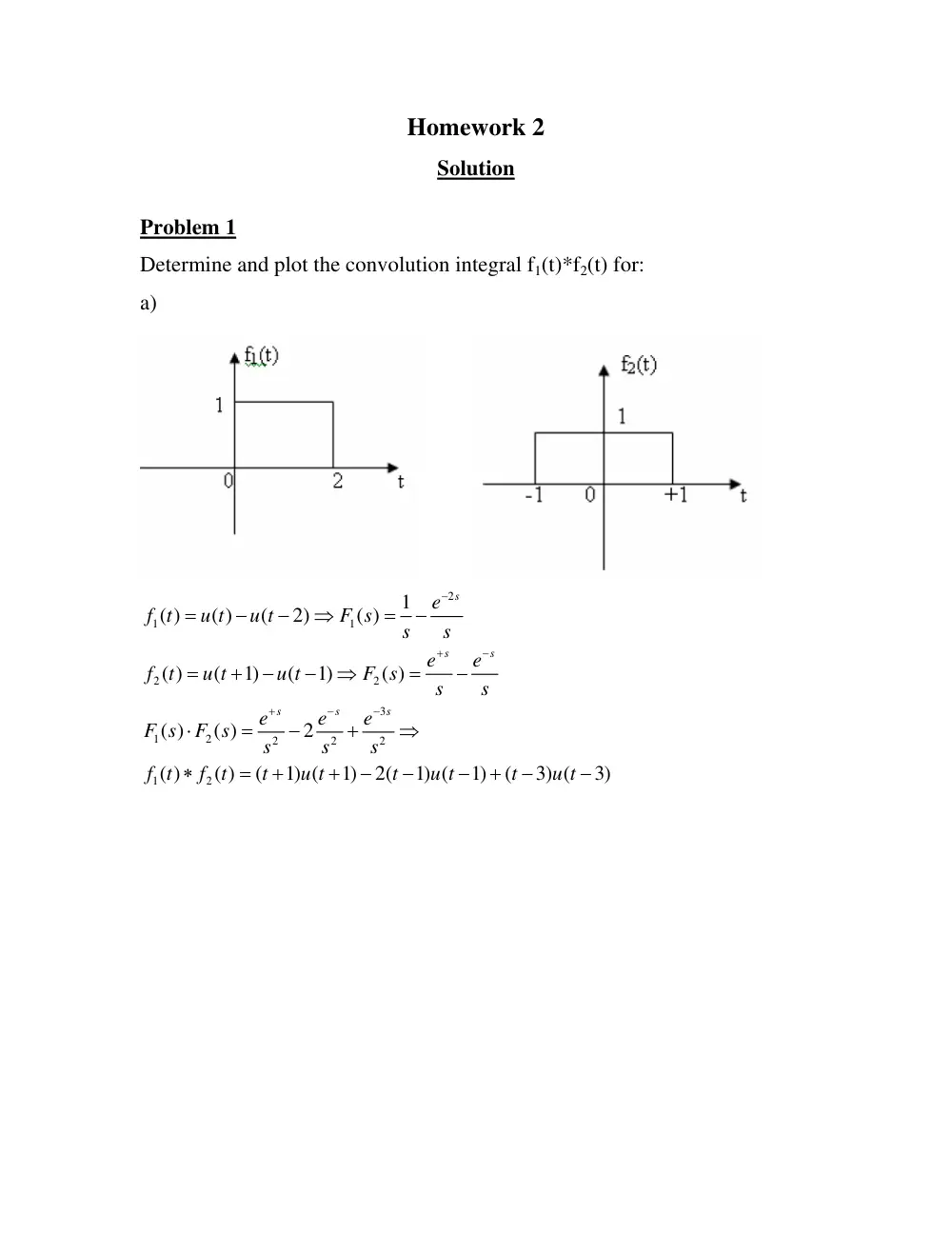
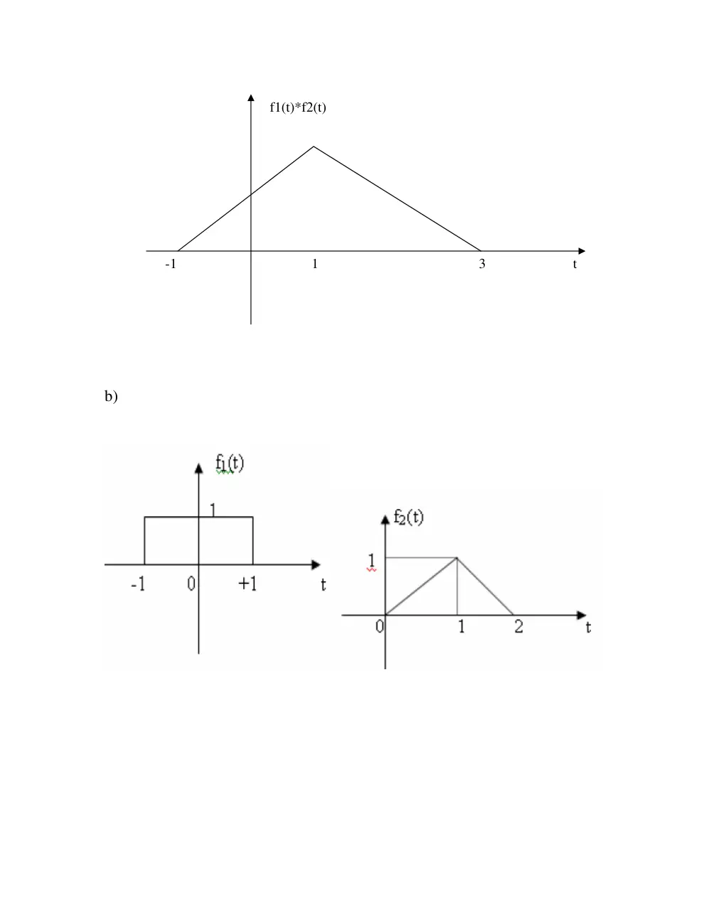
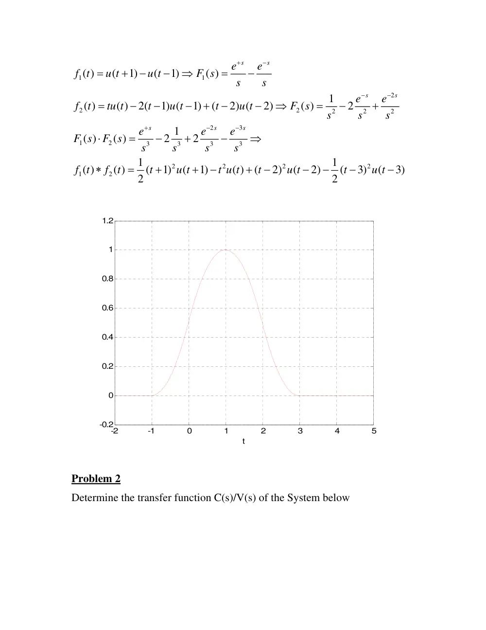
Determine and plot the convolution integral f1(t)*f2(t) for:
a)
2
1
1
2
2
3
1
2
2
2
2
1
2
1
( )
( )
(
2)
( )
( )
(
1)
(
1)
( )
( )
( )
2
( )
( )
(
1) (
1)
2(
1) (
1)
(
3) (
3)
s
s
s
s
s
s
e
f t
u t
u t
F s
s
s
e
e
f t
u t
u t
F s
s
s
e
e
e
F s
F s
s
s
s
f t
f t
t
u t
t
u t
t
u t
−
+
−
+
−
−
=
−
−
⇒
=
−
=
+
−
−
⇒
=
−
⋅
=
−
+
⇒
∗
=
+
+
−
−
−
+
−
−
b)
t
3
1
-1
f1(t)*f2(t)
1
1
2
2
2
2
2
2
2
3
1
2
3
3
3
3
2
2
2
2
1
2
( )
(
1)
(
1)
( )
1
( )
( )
2(
1) (
1)
(
2) (
2)
( )
2
1
( )
( )
2
2
1
1
( )
( )
(
1)
(
1)
( )
(
2)
(
2)
(
3)
(
3)
2
2
s
s
s
s
s
s
s
e
e
f t
u t
u t
F s
s
s
e
e
f t
tu t
t
u t
t
u t
F s
s
s
s
e
e
e
F s
F s
s
s
s
s
f t
f t
t
u t
t u t
t
u t
t
u t
+
−
−
−
+
−
−
=
+
−
−
⇒
=
−
=
−
−
−
+
−
−
⇒
=
−
+
⋅
=
−
+
−
⇒
∗
=
+
+
−
+
−
−
−
−
−
-2
-1
0
1
2
3
4
5
-0.2
0
0.2
0.4
0.6
0.8
1
1.2
t
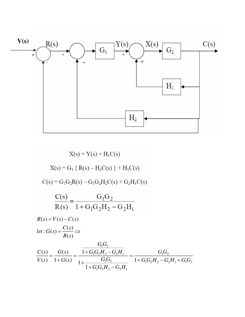
Problem 2
Determine the transfer function C(s)/V(s) of the System below
1
2
1
2
2
2
1
1
2
1
2
1
2
2
2
1
1
2
1
2
2
2
1
( )
( )
( )
( )
:
( )
( )
1
( )
( )
( )
1
( )
1
1 1
R s
V s
C s
C s
let G s
R s
G G
G G H
G H
G G
C s
G s
G G
V s
G s
G G H
G H
G G
G G H
G H
=
−
=
⇒
+
−
=
=
=
+
+
−
+
+ +
−
-
+
V(s)
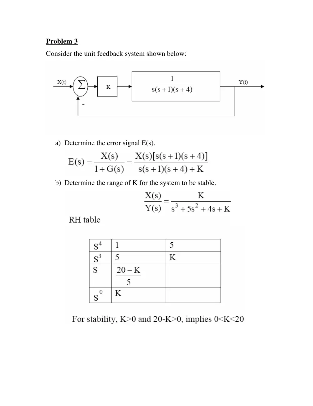
Problem 3
Consider the unit feedback system shown below:
a) Determine the error signal E(s).
b) Determine the range of K for the system to be stable.
Problem 4
The transfer function of a linear control system is given by:
2
( )
1
( )
3
2
C s
R s
s
s
=
+
+
a) Determine the state equation for this system.
b) Determine the corresponding output equation.
Problem 5
The input signal of the LTI system shown below (initially at rest) is
x(t) = u(t)-u(t-3)
The impulse responses of the subsystems are:
(
)
2
1( )
( )
t
t
h t
e
e
u t
−
−
=
+
3
2( )
t ( )
h t
e
= − u t
a) Compute the impulse response h(t) of the overall system.
1
2
1
2
1
1
( )
1
2
1
( )
3
1
1
1
( )
( )
( )
1
2
3
1
1
(
1)(
3)
(
2)(
3)
1
2
3
H s
s
s
H
s
s
H s
H s
H
s
s
s
s
s
s
s
s
A
B
C
s
s
s
=
+ +
+
=
+
⇒
⎛
⎞
=
⋅
=
+
⋅
⎜
⎟
+
+
+
⎝
⎠
=
+
+
+
+
+
=
+
+
+
+
+
Solving for A, B, and C we find:
A = 1; B = 0; C = -1 �
(
)
3
1
1
( )
1
3
( )
( )
t
t
H s
s
s
h t
e
e
u t
−
−
=
−
⇒
+
+
=
−
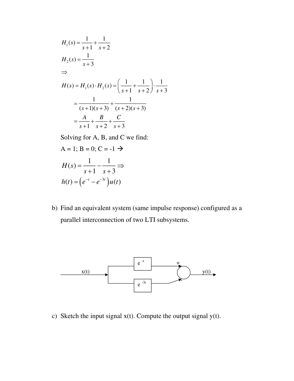
b) Find an equivalent system (same impulse response) configured as a
parallel interconnection of two LTI subsystems.
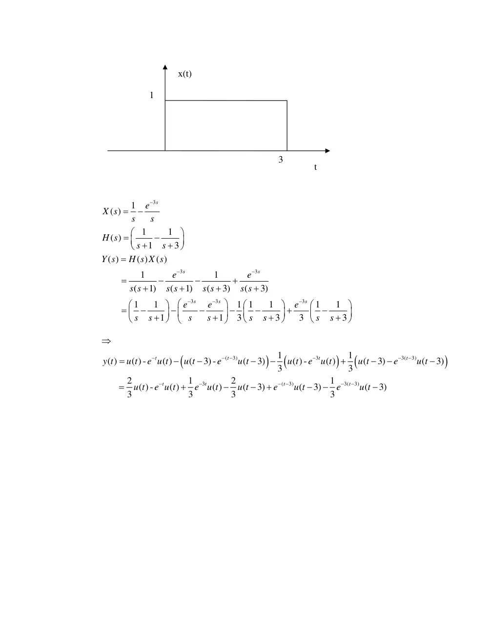
c) Sketch the input signal x(t). Compute the output signal y(t).
e -t
e -3t
+
-
x(t)
y(t)
3
3
3
3
3
3
1
( )
1
1
( )
1
3
( )
( )
( )
1
1
(
1)
(
1)
(
3)
(
3)
1
1
1 1
1
1
1
1
1
3
3
3
3
s
s
s
s
s
s
e
X s
s
s
H s
s
s
Y s
H s X s
e
e
s s
s s
s s
s s
e
e
e
s
s
s
s
s
s
s
s
−
−
−
−
−
−
=
−
⎛
⎞
=
−
⎜
⎟
+
+
⎝
⎠
=
=
−
−
+
+
+
+
+
⎛
⎞
⎛
⎞
⎛
⎞
⎛
⎞
=
−
−
−
−
−
+
−
⎜
⎟
⎜
⎟
⎜
⎟
⎜
⎟
+
+
+
+
⎝
⎠
⎝
⎠
⎝
⎠
⎝
⎠
(
)
(
)
(
)
(
3)
3
3(
3)
3
(
3)
3(
3)
1
1
( )
( ) -
( )
(
3) -
(
3)
( ) -
( )
(
3)
(
3)
3
3
2
1
2
1
( ) -
( )
( )
(
3)
(
3)
(
3)
3
3
3
3
t
t
t
t
t
t
t
t
y t
u t
e u t
u t
e
u t
u t
e
u t
u t
e
u t
u t
e u t
e
u t
u t
e
u t
e
u t
−
−
−
−
−
−
−
−
−
−
−
−
⇒
=
−
−
−
−
+
−
−
−
=
+
−
−
+
−
−
−
t
x(t)
1
3
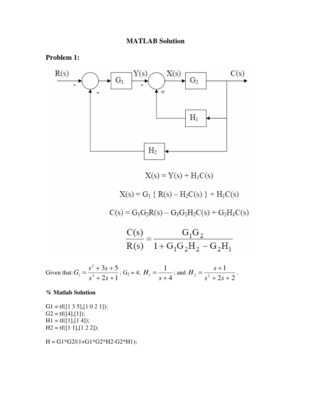
MATLAB Solution
Problem 1:
Given that:
1
2
5
3
3
2
1
+
+
+
+
=
s
s
s
s
G
; G2 = 4;
4
1
1
H = s +
; and
2
2
1
2
2
+
+
+
=
s
s
s
H
.
% Matlab Solution
G1 = tf([1 3 5],[1 0 2 1]);
G2 = tf([4],[1]);
H1 = tf([1],[1 4]);
H2 = tf([1 1],[1 2 2]);
H = G1*G2/(1+G1*G2*H2-G2*H1);
Problem 2
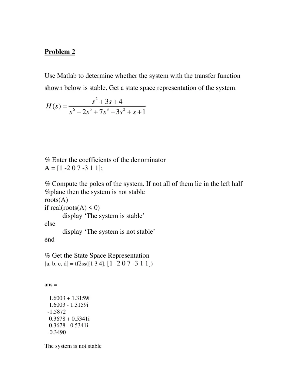
Use Matlab to determine whether the system with the transfer function
shown below is stable. Get a state space representation of the system.
2
6
5
3
2
3
4
( )
2
7
3
1
s
s
H s
s
s
s
s
s
+
+
=
−
+
−
+ +
% Enter the coefficients of the denominator
A = [1 -2 0 7 -3 1 1];
% Compute the poles of the system. If not all of them lie in the left half
%plane then the system is not stable
roots(A)
if real(roots(A) < 0)
display ‘The system is stable’
else
display ‘The system is not stable’
end
% Get the State Space Representation
[a, b, c, d] = tf2ss([1 3 4], [1 -2 0 7 -3 1 1])
ans =
1.6003 + 1.3159i
1.6003 - 1.3159i
-1.5872
0.3678 + 0.5341i
0.3678 - 0.5341i
-0.3490
The system is not stable
a =
2 0 -7 3 -1 -1
1 0 0 0 0 0
0 1 0 0 0 0
0 0 1 0 0 0
0 0 0 1 0 0
0 0 0 0 1 0
b =
1
0
0
0
0
0
c =
0 0 0 1 3 4
d =
0