
EECE 340 Homework Problem Set 3, Summer 2011
American University of Beirut · Signals and Systems · 6 pages · Dr. Fadi Karameh
More EECE 340 files
- Homework 3 · Spring 2016HomeworkView
- Homework 1 Solution · Spring 2016Homework · with solutionView
- Homework 4 · Spring 2016HomeworkView
- Homework 3 Solution · Spring 2016Homework · with solutionView
- Homework 4 Solution · Spring 2016Homework · with solutionView
- Homework 1 · Spring 2016HomeworkView
- Homework 2 Solution · Spring 2016Homework · with solutionView
- Homework 2 · Spring 2016HomeworkView
Show the text of this homework
EECE340, Summer 2011–Fadi N Karameh
1
AMERICAN UNIVERSITY OF BEIRUT
Department of Electrical and Computer Engineering
EECE340 Signals and Systems -Summer 2011
Prof Karameh
Problem Set 3
Out: Thursday July 14, 2011
Due: Thurs July 21, 2011
Work individually and write your complete solutions on clean paper. Start early, no
extensions will be allowed.
Problem 1
Find the unit sample response h[n] for each of the system functions given below:
(1)
˜H(z) =
1
(1 + 1
2z−1)(1 − 4z−1)(1 − 3z−1)
˜H(z) is stable system
(2)
˜H(z) = z3 − 2z
z − 2 ,
˜H(z) is an anti-causal system
(3)
˜H(z) =
1
(1 − 4z−1)(1 − 1
3z−1),
R.O.C.
1
3 < |z| < 4
.
Problem 2
For each of the following pairs of input sequences x[n] and unit sample responses
h[n], find the output y[n] = x[n] ⋆ h[n] using convolution. Then verify the result
using the Z-transform.
a) x[n] = δ[n + 1] + 1
2δ[n] + δ[n − 1] + 3
2δ[n − 2],
h[n] = δ[n + 1] − δ[n] + δ[n − 1].
b) x[n] = (−3)nu[−n − 1],
h[n] = (1
2)nu[n + 2].
EECE340, Summer 2011–Fadi N Karameh
2
Problem 3
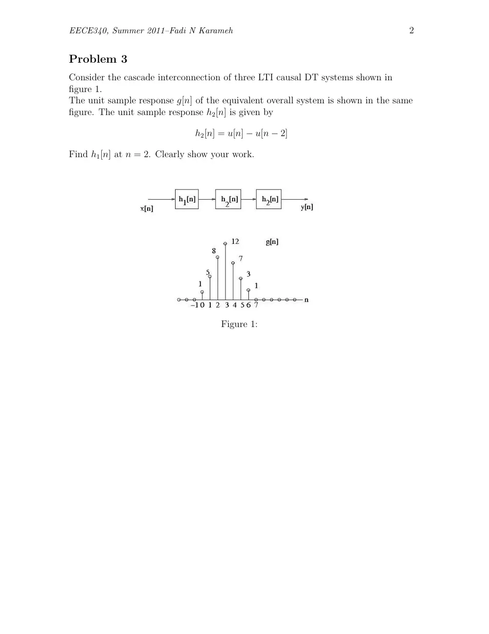
Consider the cascade interconnection of three LTI causal DT systems shown in
figure 1.
The unit sample response g[n] of the equivalent overall system is shown in the same
figure. The unit sample response h2[n] is given by
h2[n] = u[n] − u[n − 2]
Find h1[n] at n = 2. Clearly show your work.
Figure 1:
EECE340, Summer 2011–Fadi N Karameh
3
Problem 4
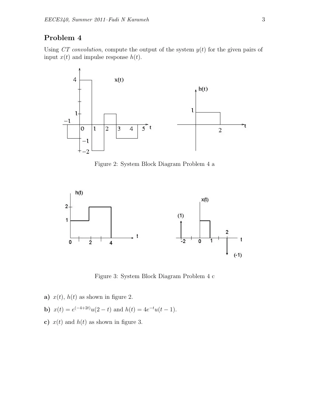
Using CT convolution, compute the output of the system y(t) for the given pairs of
input x(t) and impulse response h(t).
Figure 2: System Block Diagram Problem 4 a
Figure 3: System Block Diagram Problem 4 c
a) x(t), h(t) as shown in figure 2.
b) x(t) = e(−4+2t)u(2 − t) and h(t) = 4e−tu(t − 1).
c) x(t) and h(t) as shown in figure 3.
EECE340, Summer 2011–Fadi N Karameh
4
Problem 5
An CT LTI system has an input x(t), a system function H(s) and an output y(t).
We are given the following:
X(s) = s + 5
s − 4
x(t) = 0, t > 0 and the corresponding output
y(t) = −2
3e4tu(−t) + 1
3e−2tu(t).
a) Determine H(s) and its region of convergence.
b) Determine h(t), the impulse response of the system.
Problem 6
(a) Consider a CT LTI system described by the following differential equation
d2y
dt2 − 2dy(t)
dt
− 3y(t) = x(t)
(a-1) Determine the impulse response h(t) if this system stable.
(a-2) Determine the impulse response h(t) if this system is neither causal nor
stable.
(b) Consider a CT LTI system S with inputs x(t) and output y(t).
If an input xo(t) = 2e−3tu(t − 1) is applied, the corresponding (unknown)
output is yo(t). If an input x1(t) = dxo(t)
dt , then the corresponding output is
y1(t) = −3yo(t) + e−2(t−1)u(t − 1).
Find the impulse response h(t) of this system.
Problem 7
Determine the Continuous time signal corresponding to each of the following Fourier
Transforms
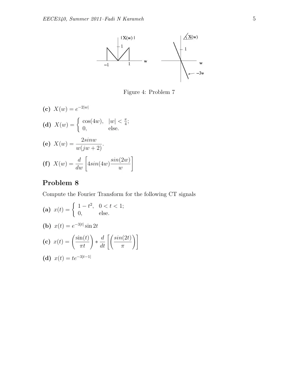
(a) X(w) is given by the magnitude and phase plots of figure 4
(b) X(w) =
w − 1,
1 ≤ w < 2;
sign(w),
2 < |w| ≤ 3;
w + 1,
−2 ≤ w < −1;
0,
else.
EECE340, Summer 2011–Fadi N Karameh
5
Figure 4: Problem 7
(c) X(w) = e−2|w|
(d) X(w) =
�
cos(4w),
|w| < π
4;
0,
else.
(e) X(w) =
2sinw
w(jw + 2).
(f) X(w) = d
dw
�
4sin(4w)sin(2w)
w
�
Problem 8
Compute the Fourier Transform for the following CT signals
(a) x(t) =
�
1 − t2,
0 < t < 1;
0,
else.
(b) x(t) = e−3|t| sin 2t
(c) x(t) =
�sin(t)
πt
�
∗ d
dt
��sin(2t)
π
��
(d) x(t) = te−3|t−1|
EECE340, Summer 2011–Fadi N Karameh
6
Problem 9
Most of the modulation and demodulation schemes we discussed so far used
multipliers as basic elements. Multipliers are often difficult to implement in
practice. Therefore, many practical systems use a nonlinear element. In this
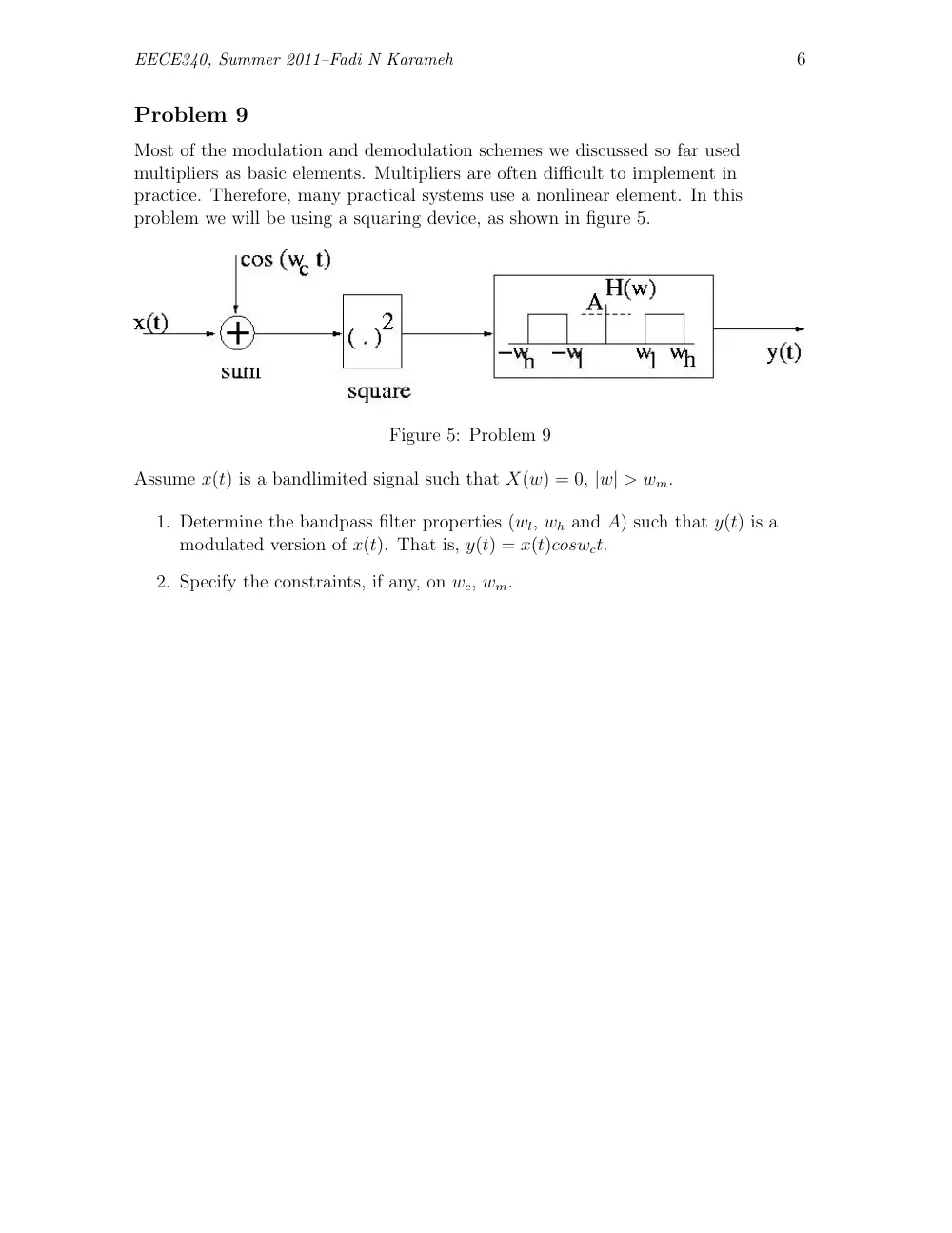
problem we will be using a squaring device, as shown in figure 5.
Figure 5: Problem 9
Assume x(t) is a bandlimited signal such that X(w) = 0, |w| > wm.
1. Determine the bandpass filter properties (wl, wh and A) such that y(t) is a
modulated version of x(t). That is, y(t) = x(t)coswct.
2. Specify the constraints, if any, on wc, wm.