
EECE 340 Homework Problem Set 4, Summer 2011
American University of Beirut · Signals and Systems · 5 pages · Dr. Fadi Karameh
More EECE 340 files
- Homework 3 · Spring 2016HomeworkView
- Homework 1 Solution · Spring 2016Homework · with solutionView
- Homework 4 · Spring 2016HomeworkView
- Homework 3 Solution · Spring 2016Homework · with solutionView
- Homework 4 Solution · Spring 2016Homework · with solutionView
- Homework 1 · Spring 2016HomeworkView
- Homework 2 Solution · Spring 2016Homework · with solutionView
- Homework 2 · Spring 2016HomeworkView
Show the text of this homework
EECE340, Summer 2011–Fadi N Karameh
1
AMERICAN UNIVERSITY OF BEIRUT
Department of Electrical and Computer Engineering
EECE340 Signals and Systems -Summer 2011
Prof Karameh
Problem Set 4
Out: Thursday July 21, 2011
Due: Wednesday July 27, 2011
Work individually and write your complete solutions on clean paper. Start early, no
extensions will be allowed.
Problem 1
In this problem, we will consider an AM modulation scheme called Single Side Band
(SSB -AM). Here we transmit only a single side of the signal, knowing that it can
be completely recovered at the receiving end.
This will free up a wider area in
the frequency spectrum, and thus allow for more signals to be multiplexed on the
frequency axis.
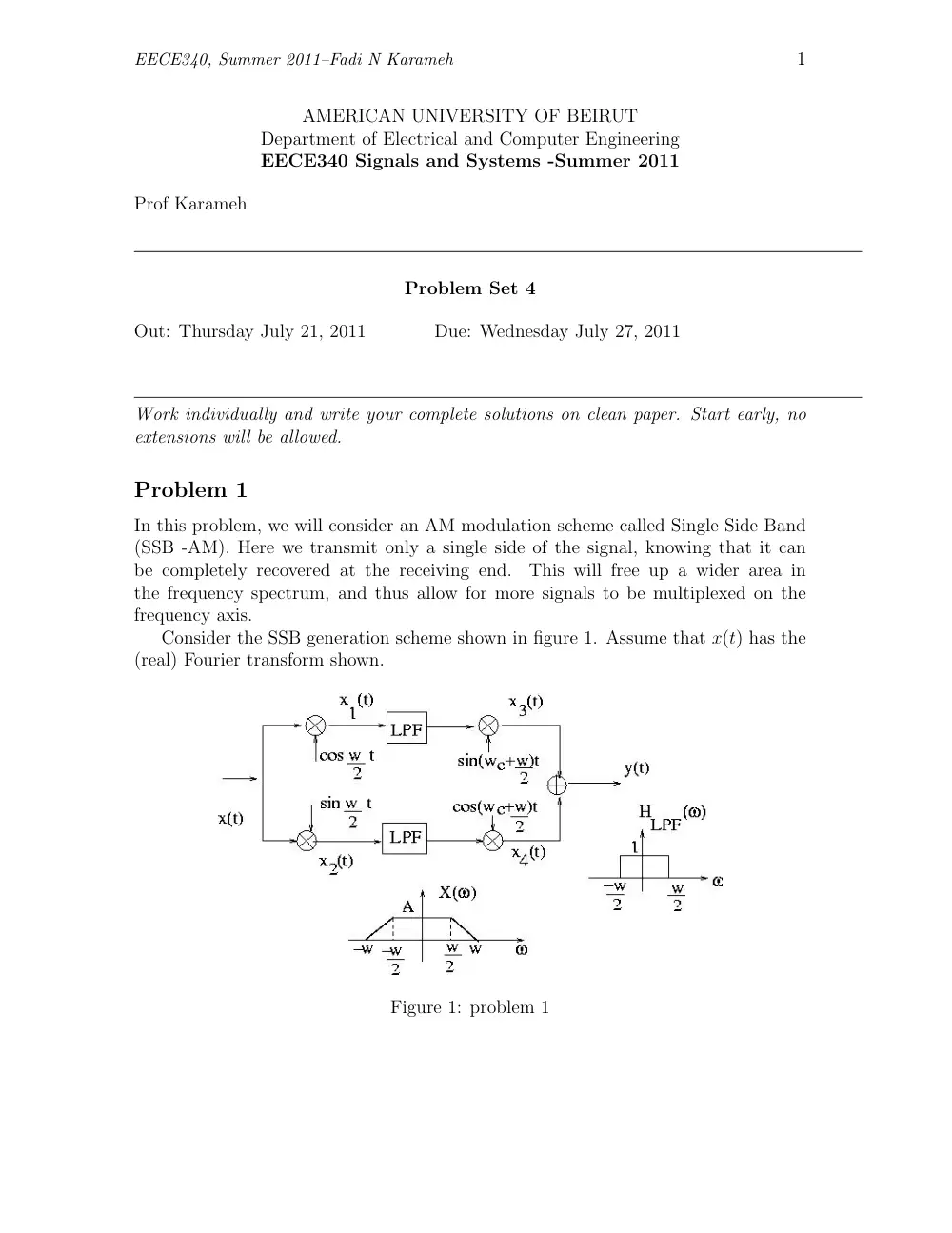
Consider the SSB generation scheme shown in figure 1. Assume that x(t) has the
(real) Fourier transform shown.
Figure 1: problem 1
EECE340, Summer 2011–Fadi N Karameh
2
a) Sketch the Fourier transform of x1(t), x2(t), x3(t), x4(t), and y(t). This should
demonstrate that y(t) is in fact single-side band modulated version of x(t) mod-
ulated on the carrier wc.
b) Suggest a scheme for recovering the original signal x(t) from the SSB-AM signal
y(t).
Problem 2
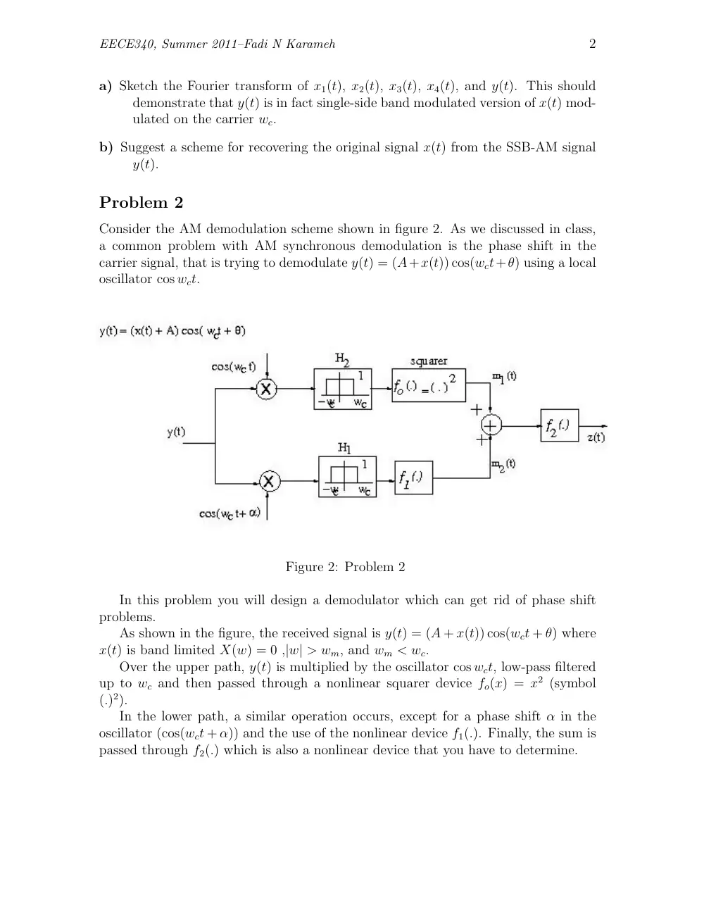
Consider the AM demodulation scheme shown in figure 2. As we discussed in class,
a common problem with AM synchronous demodulation is the phase shift in the
carrier signal, that is trying to demodulate y(t) = (A+x(t)) cos(wct+θ) using a local
oscillator cos wct.
Figure 2: Problem 2
In this problem you will design a demodulator which can get rid of phase shift
problems.
As shown in the figure, the received signal is y(t) = (A + x(t)) cos(wct + θ) where
x(t) is band limited X(w) = 0 ,|w| > wm, and wm < wc.
Over the upper path, y(t) is multiplied by the oscillator cos wct, low-pass filtered
up to wc and then passed through a nonlinear squarer device fo(x) = x2 (symbol
(.)2).
In the lower path, a similar operation occurs, except for a phase shift α in the
oscillator (cos(wct + α)) and the use of the nonlinear device f1(.). Finally, the sum is
passed through f2(.) which is also a nonlinear device that you have to determine.
EECE340, Summer 2011–Fadi N Karameh
3
(a) Find the output m1(t) of the upper path after the squarer. Hint: use trigono-
metric identities.
(b) Based on the result you obtained in (a), determine the phase shift α and the
nonlinear functions f1(.) and f2(.) such that the output z(t) DOES NOT depend
on the phase shift θ. (i.e., it contains no terms like cos θ or sin θ).
Problem 3
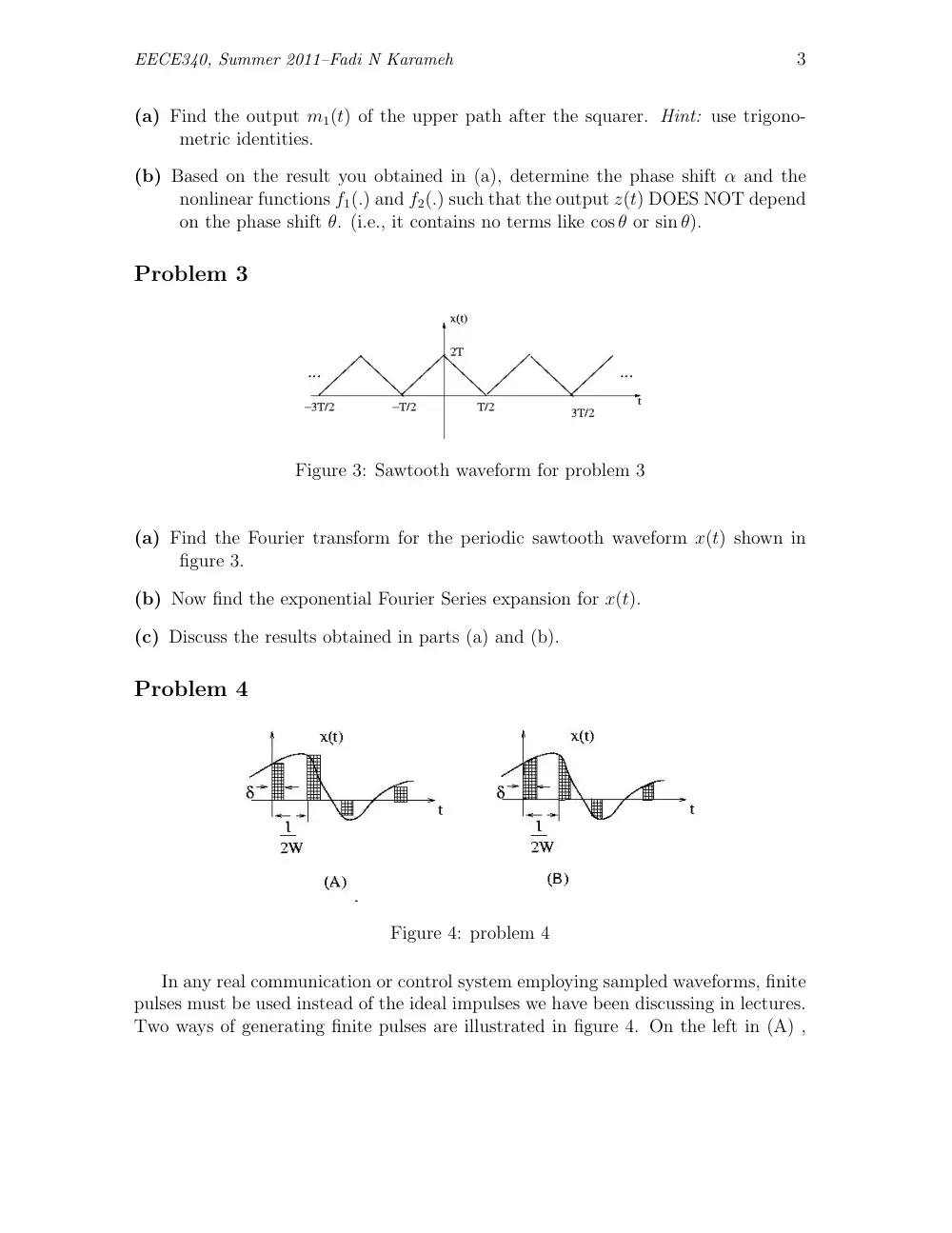
Figure 3: Sawtooth waveform for problem 3
(a) Find the Fourier transform for the periodic sawtooth waveform x(t) shown in
figure 3.
(b) Now find the exponential Fourier Series expansion for x(t).
(c) Discuss the results obtained in parts (a) and (b).
Problem 4
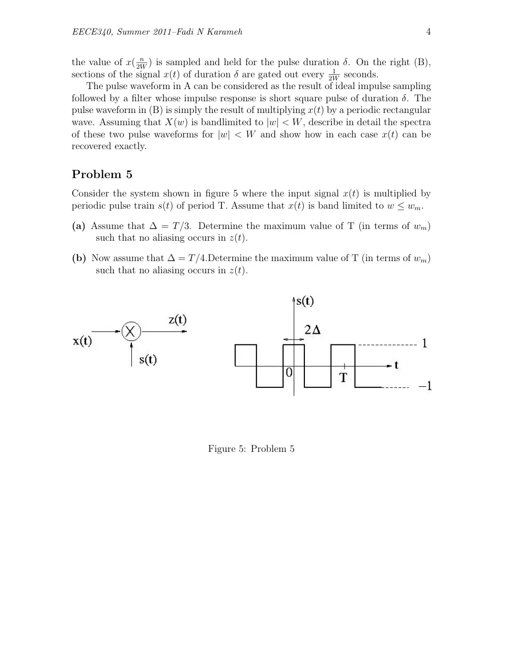
Figure 4: problem 4
In any real communication or control system employing sampled waveforms, finite
pulses must be used instead of the ideal impulses we have been discussing in lectures.
Two ways of generating finite pulses are illustrated in figure 4. On the left in (A) ,
EECE340, Summer 2011–Fadi N Karameh
4
the value of x( n
2W ) is sampled and held for the pulse duration δ. On the right (B),
sections of the signal x(t) of duration δ are gated out every
1
2W seconds.
The pulse waveform in A can be considered as the result of ideal impulse sampling
followed by a filter whose impulse response is short square pulse of duration δ. The
pulse waveform in (B) is simply the result of multiplying x(t) by a periodic rectangular
wave. Assuming that X(w) is bandlimited to |w| < W, describe in detail the spectra
of these two pulse waveforms for |w| < W and show how in each case x(t) can be
recovered exactly.
Problem 5
Consider the system shown in figure 5 where the input signal x(t) is multiplied by
periodic pulse train s(t) of period T. Assume that x(t) is band limited to w ≤ wm.
(a) Assume that ∆ = T/3. Determine the maximum value of T (in terms of wm)
such that no aliasing occurs in z(t).
(b) Now assume that ∆ = T/4.Determine the maximum value of T (in terms of wm)
such that no aliasing occurs in z(t).
Figure 5: Problem 5
EECE340, Summer 2011–Fadi N Karameh
5
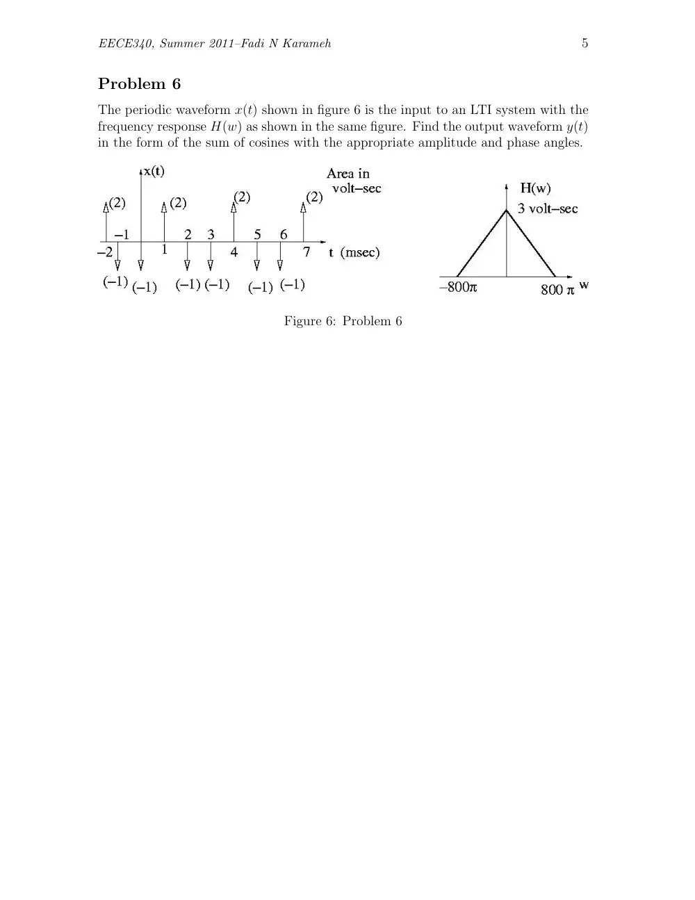
Problem 6
The periodic waveform x(t) shown in figure 6 is the input to an LTI system with the
frequency response H(w) as shown in the same figure. Find the output waveform y(t)
in the form of the sum of cosines with the appropriate amplitude and phase angles.
Figure 6: Problem 6