
EECE 340 Homework, Spring 2001
American University of Beirut · Signals and Systems · 7 pages



More EECE 340 files
- Homework 3 · Spring 2016HomeworkView
- Homework 1 Solution · Spring 2016Homework · with solutionView
- Homework 4 · Spring 2016HomeworkView
- Homework 3 Solution · Spring 2016Homework · with solutionView
- Homework 4 Solution · Spring 2016Homework · with solutionView
- Homework 1 · Spring 2016HomeworkView
- Homework 2 Solution · Spring 2016Homework · with solutionView
- Homework 2 · Spring 2016HomeworkView
Show the text of this homework
EECE 340 — Signals and Systems
Homework # 1
Consider the following voltage signal across a 50 Q resistance.
11
ately
SO= 2rel
Determine the energy dissipated by jt) across the resistance.
-hetst
Hint: rect(t)=3 2 2
0, elsewhere
1.2 Consider the signal f(t) =e" for allt.
Apply the time-domain integration formulas for energy and average power to determine the
nature of the signal f(t).
Consider the following system:
sW=TIOl=4 f f@dr tut).
Determine the impulse response A(t) of the system and the system output g(t) when the input
13
fis given by f(t) =e u(t).
1.4 Consider the system shown in the figure below.
t
>) JO dt. = ——~> a(t)
SAC)
In this system, f(t) is the input signal and g(t) is the output signal. Determine the impulse
response, /i(t), of the system and the system response, g(t), for an input f(t)=0(t-tq), where d(t)
is the unit impulse function. Conclude whether the system is time-invariant or time-varying.
Page 1 of 2
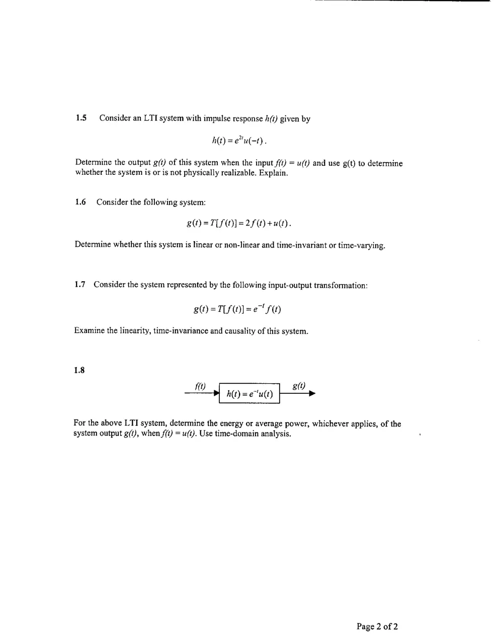
1.5 Consider an LTI system with impulse response /(t) given by
A(t) = e*u(-t).
Determine the output g/t) of this system when the input f(t) = u(t) and use g(t) to determine
whether the system is or is not physically realizable. Explain.
1.6 Consider the following system:
BS =TIPO]=2f(O +e).
Determine whether this system is linear or non-linear and time-invariant or time-varying.
1.7 Consider the system represented by the following input-output transformation:
gs) =T/(M) =e" FO
Examine the linearity, time-invariance and causality of this system.
18
ue h(t) =e"u(t) | sO,
For the above LTI system, determine the energy or average power, whichever applies, of the
system output g(t), when f(t) = u(t). Use time-domain analysis.
Page 2 of 2
EECE 340 — Signals and Systems
Homework # 1 — Solution
1.1 The voltage signal
S(O = 2rect( Ty
is across a 50Q resistance. Using
, erect
rect(t) = 2 2
0, elsewhere
then
IP yy
S(t) = 2rect(
_f2,0<¢s or
~ 0, elsewhere
T
E, at dt = Ah 27 Joules
50 50. 25
1.2. Consider the signal
fW=e", allt
E= ferar=-Le" =1(e?-e*)=4e" 0
2 2° le 9 2
lyr or
—l|e -e
P, = lim— a edt = lim 2| )
Ta0 T T30 T
T -T T
= lim =-lim 2— = tim = 0
Toa 2T Taw QT T2027
=> /(®) is neither an energy nor a power signal
1.3. The following system is considered:
s@=T[S(t)]=4 [ f@dr+uO
A(t) =T[ S(t) ]=4 [st@ar+u)
For? <0, A(t) =0
For?20, A(t) =4u()+uO=Fa &)
For f(t) =e"u(t), the system output is:
g=4 | f@dr+uy
t
4 Jevar +u(t)= -26*|' +u(t)
Qa
2(1-e* u(t) +u(e)
3-2e*' u(t)
1.4 The system shown in the figure below is considered.
t
cA) my fdr -— 2)
The system impulse response is the system output, denoted by A(t), when the input f(t) = d(t).
Thus, A(t) = fetodr = Jo(e)de
0, t<0
-{ t>0
=u(t)
For f(t) =6d(t-1,),
1
a= fets(r-1,)dr =e" [o(r-1)ae
0
=e“u(t-t,)
Obviously, the system, which is formed by the cascaded connection of a multiplier and integrator is a
time-varying system although the integrator is time-invariant.
1.5 The LTI system with impulse response h(t) given by
h(t) =e"u(-t) is considered.
The output g(t) of this system when the input f(t) = u(t) can be obtained using convolution.
A
gy eu(-r)
_ >
t 0 ;
Ly py 1
=5( 2, -0)=<e*
1; 1
Fort20,g(t)= fevde=se"| =>
an t<0
=>g()= 1
-, t20
2
The system input is f(t) = u(t). So, it applied for t 2 0. But, the system produces an output for t < 0;
i.e., before the input is applied. Hence, the system is not physically realizable.
1.6 The following system is considered:
BO=TILO]= 2/04 ue).
Linearity:
Tla AMt+a,40]= 2a, fi()+ 2a, f,() +u(t)
#aT[fO]+a7[40]
= 2a, fi(t)+u(t)+2a, f,(t)+u(t)
= 2a, f(O+2a, f+ 2u(y
So, the system is non-linear.
Time-invariance:
T[ f(t-t) |= 2s (¢-%) +4 (1) # g(t-4) =2f (1-4) +u(t-4)
Hence, the system is time-varying.
1.7 The system represented by the following input-output transformation is considered:
s@)=TPMO]=e" SO
Linearity:
Tla fO+a,f4,0]=47[A0]+47[40]???
Ta fOrtaAOl=e"[ahOr+ahO]
sae’ fOt+ae"f0
=al[f£O]+a7[40]
So, the system is linear.
Causality:
a()=e S(t)
Hence, the system output at time 4, depends on the input at time 4).
=> the system is causal
Time-invariance:
g(t-%) =e" £(t-4) #7 [F(t-%) |= eS (t-4)
Hence, the system is time-varying.
1.8
ee A(t) = e'u(t) | 8
When the input to the system is //)=u(t), then the output is g(f)=(/-e"Ju(t). This can be verified using
convolution.
It is obvious from the plot of g(t) that g(t) has an « energy. Hence g(t) is not an energy signal.
g(t) is a power signal if it has a finite non-zero average power. As shown in the computations done
below, g(t) is therefore a power signal.
P, = tim> [(1-e*) dt = unt] fos e #4]
wv Tae T Ta0 T
i
T