
EECE 340 Homework, Spring 2008
American University of Beirut · Signals and Systems · 5 pages



More EECE 340 files
- Homework 3 · Spring 2016HomeworkView
- Homework 1 Solution · Spring 2016Homework · with solutionView
- Homework 4 · Spring 2016HomeworkView
- Homework 3 Solution · Spring 2016Homework · with solutionView
- Homework 4 Solution · Spring 2016Homework · with solutionView
- Homework 1 · Spring 2016HomeworkView
- Homework 2 Solution · Spring 2016Homework · with solutionView
- Homework 2 · Spring 2016HomeworkView
Show the text of this homework
American University of Beirut
Department of Electrical and Computer Engineering
EECE 440 Signals and Systems
Homework 3: Due July 18, 2006
Problem 1
Two signals m1(t) and m2(t), both band-limited to 500 rad/s, are to be
transmitted simultaneously over a channel as shown below
m1(t)
+ b X c
m2(t) X
a
2 cos20,000t
2 cos10,000t
The modulated signal at point c is transmitted over a channel. Determine the
bandwidth of the output signal at point c.
Problem 2
The spectrum of the two band-limited signals s1(t) and s2(t) are shown
below.
S1(ω) S2(ω)
-5 rad/s 5 rad/s -2 rad/s 2 rad/s
Determine
the
bandwidth
of
the
signal
y(t)
given
by:
y(t)=s1(t)+10s2(t)cos10t.
Problem 3
The signal
t
cos
T
rect t
)t(
f
ω0
⎟
⎠
⎞
⎜
⎝
⎛
=
is applied to the following system
f(t) X Filter g(t)
cos(2ω0t)
The filter in the above figure is considered to be a unity gain ideal band-pass
filter of mid-frequency (ω0) and bandwidth (2W) rad/s. Determine the
output of this filter. Assume that rect(t/T) has a bandwidth of W rad/s.
Problem 4
An electric filter system has the frequency response
ω
+
ω
ω =
j
1
j
H( )
What type of filter is this?
Problem 5
Consider the signal s(t) given by:
20cos(220 )t
12cos(160 )t
)t(s
+
=
. This
signal is present at the input of a unity gain ideal band-pass filter of mid-
frequency 210 rad/s and bandwidth 25 rad/s. Determine the average power
at the output of the filter.
Problem 6
The spectrum of the signals f(t) and g(t) are shown below. Express g(t) as a
function of f(t).
F(ω)
1
ω
-W W
G(ω)
1
ω
-ω0 -ω0 +W ω0 -W ω0
Problem 7
A sinusoidal signal of frequency 1 Hz is to be sampled periodically. Find
the maximum allowable time interval between samples.
Problem 8
The system shown below is used for scrambling audio signals.
m(t) X LPF y(t)
0-15 KHz
2 cos(30,000π)t
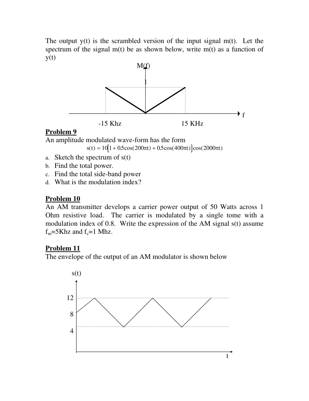
The output y(t) is the scrambled version of the input signal m(t). Let the
spectrum of the signal m(t) be as shown below, write m(t) as a function of
y(t)
M(f)
1
f
-15 Khz 15 KHz
Problem 9
An amplitude modulated wave-form has the form
[
]
s t
t
t
t
( )
. cos(
)
. cos(
) cos(
)
=
+
+
10 1
05
200
05
400
2000
π
π
π
a. Sketch the spectrum of s(t)
b. Find the total power.
c. Find the total side-band power
d. What is the modulation index?
Problem 10
An AM transmitter develops a carrier power output of 50 Watts across 1
Ohm resistive load. The carrier is modulated by a single tome with a
modulation index of 0.8. Write the expression of the AM signal s(t) assume
fm=5Khz and fc=1 Mhz.
Problem 11
The envelope of the output of an AM modulator is shown below
s(t)
12
8
4
t
Determine the following:
a. The modulation index.
b. The carrier amplitude.
Problem 12
An AM modulator operates with the message signal: m(t)=-6cos(20πt)-
2cos(60πt). The unmodulated carrier is given by: c(t)=100cos(200πt) and
the modulation index is 0.5.
a. Write the time-domain expression of the AM wave s(t).
b. Write the time-domain expression of the USB of s(t) including carrier.