
MEE 320 Problems Book Chapter 1, Spring 2018
Lebanese American University · Strength of Material · 61 pages





Showing the first 10 of 61 pages. Download the PDF to see all of it.
More MEE 320 files
Show the text of this chapter
Chapter |
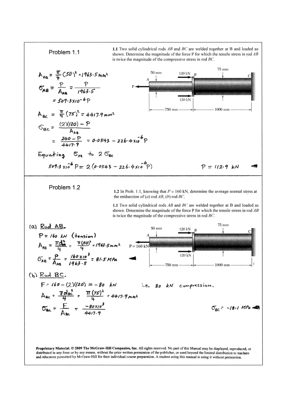
1.1 Two solid cylindrical rods AB and BC are welded together at B and loaded as
Problem 1.1 shown. Determine the magnitude of the force P for which the tensile stress in rod AB
is twice the magnitude of the compressive stress in rod BC.
75 mm
Aaa? $y =1963-5 tne 50 mm 10kN pg
-P 2. PP P
ona = Arg 1963-5
= $09-3x10" oP |
750 mm i 1000 mm >
Kae = HF CISY = 4417-7 mame
_ (220) -P
See ne
= 240 - FP = 0-0543 ~ 226-4010 P
4417-9
Equating Sa, to 2 Ce
- -6
$09-3 yi" Px Q(0-0543 ~ 226-400 P) P=Hu2aen
Problem 1.2
1.2 In Prob. 1.1, knowing that P = 160 KN, determine the average normal stress at
the midsection of (a) rod AB, (4) rod BC.
1.1 Two solid cylindrical rods AB and BC are welded together at B and loaded as
shown. Determine the magnitude of the force P for which the tensile stress in rod AB
is twice the magnitude of the compressive stress in rod BC.
( a) Rod AB. 50 mtn 75 mm
120kN B
P= /60 WW Cheusion) A
2.
No = Tae - TEM « 1962-5mm2 P=160kNE
3
Gre 7 - 462%". ens mp, <t
TROKN | :
Ang 1963-5 750 mm | 1000 mm |;
(be) Red BC.
Fr 160~(2)020) =-f0 kn Le. 80 kN compression.
2 2
Mec * Tolec : aes) = 4417-9 mint
3
Oa. * _E — _~8Oxso
< On. 2 ~/9+1 MPa <th
Aw F4IT-F a
Proprietary Material. © 2009 The McGraw-Hill Companies, Inc. All rights reserved. No part of this Manual may be displayed, reproduced, or
distributed in any form or by any means, without the prior written permission of the publisher, or used beyond the limited distribution to teachers
and educators permitted by McGraw-Hill for their individual course preparation. A student using this manual is using it without permission.
Problem 1.3
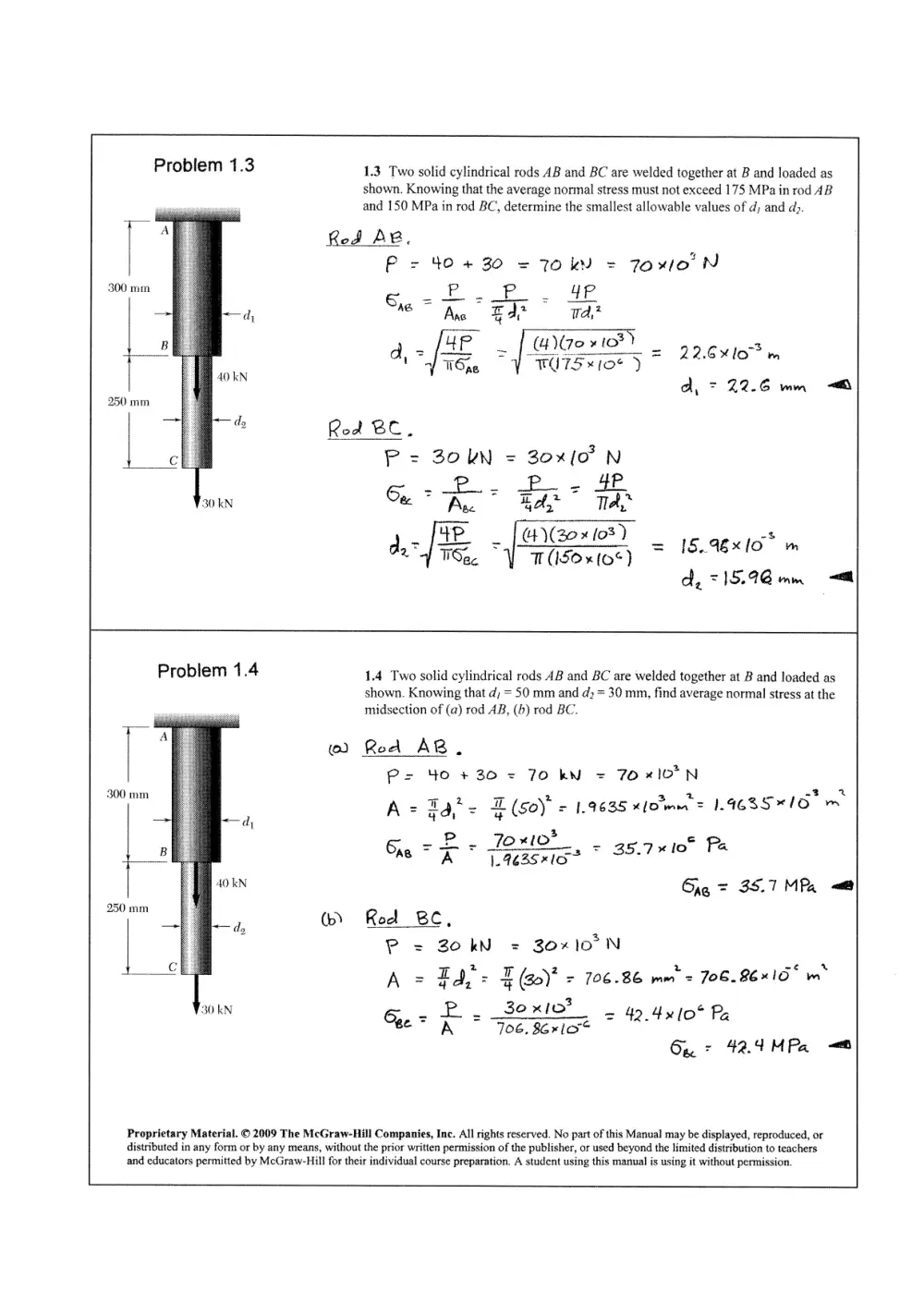
1.3 Two solid cylindrical rods AB and BC are welded together at B and loaded as
shown. Knowing that the average normal stress must not exceed 175 MPa in rod 4B
and 150 MPa in rod BC, determine the smallest allowable values of d; and dp.
Rod AB.
P = 4O+ 30 = 7OkN = Jo xlo’ N
6,
300 mm im - P - 4qP.
dy se” Ans : Ede wd,*
B up (eo xto*) “3
: > fA = 6%
an oe a= AE | UNIe HOY 22.610 m
40 kN a, = 22.6 mm =<
250 mm
— — dy Rod ciel .
c P = 30kN = 30x(O N
CG, Pp... B.- HP
30 kN & Ase 44 a Tra”
4P 4)(20 x (03) 8
> v ~AGxXxlO mM
ALG. Y masoxioey = 1S 96x!
d. =|]5.96 mn <e@
Problem 1.4 1.4 Two solid cylindrical rods AB and BC are welded together at B and loaded as
shown. Knowing that d; = 50 mm and d; = 30 mm, find average normal stress at the
midsection of (a) rod AB, (b) rod BC.
> i
(0) Road AB e
Ps 40 +30 = 70 kN = 70x10°N
“ee A = Bat = E (60) = 1.9635 xlome = 14635*10
-P 2 Toxo | Pp
iB Gre = A 1.9635x1O 35.710 FS
Cag = 3S.7 MPR
250 mm (bY Roe BC,
P = Zo kN = 30x10°N
i A = Ea, = | ()* = 706.86 mm = 706. 86%15° m*
30 kN
Proprietary Material. © 2009 The McGraw-Hill Companies, Inc. All rights reserved. No part of this Manual may be displayed, reproduced, or
distributed in any form or by any means, without the prior written permission of the publisher, or used beyond the limited distribution to teachers
and educators permitted by McGraw-Hill for their individual course preparation. A student using this manual is using it without permission.
PB. _30 x10?
= = 4 4 lo* RP.
Cee = A 706, 861 ae “
6a: 42.4MPa =
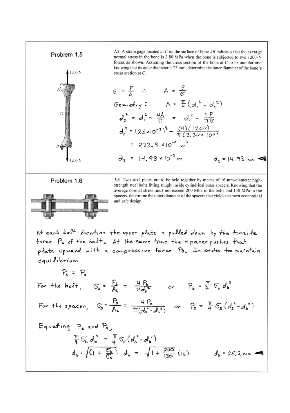
1.5 A strain gage located at C on the surface of bone AB indicates that the average
Problem 1.5 normal stress in the bone is 3.80 MPa when the bone is subjected to two 1200-N
forces as shown. Assuming the cross section of the bone at C to be annular and
knowing that its outer diameter is 25 mm, determine the inner diameter of the bone’s
1200 N cross section at C.
A _-f. - ~ &
ion - A we A SC
Geometry : A= r Ca* - a,”)
2 2 ‘A z 4P
a =a - B= dt- te
2 poe ps \t_ (4)(12 90)
dy = (28eIO*)— ra easy
B = 222.9 *10°
1200 N a, * 14.43% 107m d,= 14.93 yam “<el
Problem 1.6 1.6 Two steel plates are to be held together by means of 16-mm-diameter high-
strength steel bolts fitting snugly inside cylindrical brass spacers. Knowing that the
average normal stress must not exceed 200 MPa in the bolts and 130 MPa in the
spacers, determine the outer diameter of the spacers that yields the most economical
and safe design.
=ai—
ae
At each bolt Pocatyran the Upper plate is pudled down by the tens fe
force Py of the bolt. At the same time the spacey pushes that
P P
plate Upward with a compressive force Ts. In ovder +o maintain
equidilbecum
Bos the on Peo
in
= - _4Ps - a
For the Spacen, SSF AL T(de-de) o P= E 6s (d,’- aA, )
Equvating Py and Ps,
oa = if Se (d'- Ae)
des fi + Sb) A= fl+ BE 0) dg = 25.2 mmm <a
Problem 1.7 1.7 Each of the four vertical links has an 8 x 36-mm uniform rectangular cross
section and each of the four pins has a 16-mm diameter. Determine the maximum
value of the average normal stress in the links connecting (a) points B and D, (d)
0.4m points C and E.
Use bac ABC asa free body,
20 #8 0.025 ae ONO ’ cacee|
A B c
Fan Fee
oO! (0,080) Fy, — (0.025+0.040 )(20x10*) = ©
M
<
o
“
Feo = 32.5 jo" N Link BD js m tension.
0, ~(0,04%)F, - (o.0zs)(20x0') =O
M
3s
is
w
Fay = -125 ")0 N Link Ce as ia Com pression,
Net area of one Dink For pension = (0,008)(0,036.- 0.016 )
= 160 xlo” we For two paratle) Din Ks And = 320 xjo"* ws
Tensile stress m Drak BD.
re 32.5 oF o
(Geo * ran . hee = 101.56 "10 Spyz l0l.6 MPa aa
net
z
Area fon one Dir le in Com pression = (0.008 )(0.036)
& 2
= 288x 10° m* For two paraDlel Paks, A= S76IO m
aT) t
Proprietary Material. © 2009 The McGraw-Hill Companies, Inc. All rights reserved. No part of this Manual may be displayed, reproduced, or
distributed in any form or by any means, without the prior written permission of the publisher, or used beyond the limited’distribution to teachers
and educators permitted by McGraw-Hill for their individual course preparation. A student using this manual is using it without permission.
Problem 1 8 1.8 Knowing that the cehtral portion of the link BD has a uniform cross-sectional
area of 800 mm”, determine the ‘magnitude of the load P for which the normal stress
in that portion of BD is 50 MPa.
P A
—
O.lm Ve 6
Feo = SA + 2
= (50 * 10%) (300% ic)
_ 3 Lam Fep
° 70 *10 N AZ
BD =-/(0.56)"+ (1.92)" \ |
> 2,00 m —p
Use Free Boaly AC for statics, 056m
= . 56 “
ODM. =o: ce (Yo lo2YC.4) + LE (Hom 1?) C1. #)
- Plo.741.4) = 0
P= 33.110" N P= 38)kN <a
Problem 1.9 1.9 Knowing that link DE is 25 mm wide and 3 mm thick, determine
the normal stress in the central portion of that link when (a) 6 = 0, (b) 6 = 90°.
eo 300 mn — fot Use member CEF as a free body
it HIM, = oO
| 7 il. —P | -6°3 Fyz-(0+2) (24.0 sin®)- (0-4) (240 e036) = O
7 Foe = —/b6o sin® —3200e03 0 N
A :
240N | | j ~G 2
2 9 A ye = (01025) (01003) = 75X10 mM
Ope = fe
@) 8-0: Foe = -320 N
—320
> ad oJ XN eg,
Soe jena 4.27 MPa
(b) 0 = 40°: Foe = - (60N
-60
Goe =
E75 we”
= ~-2-12 MPa <a
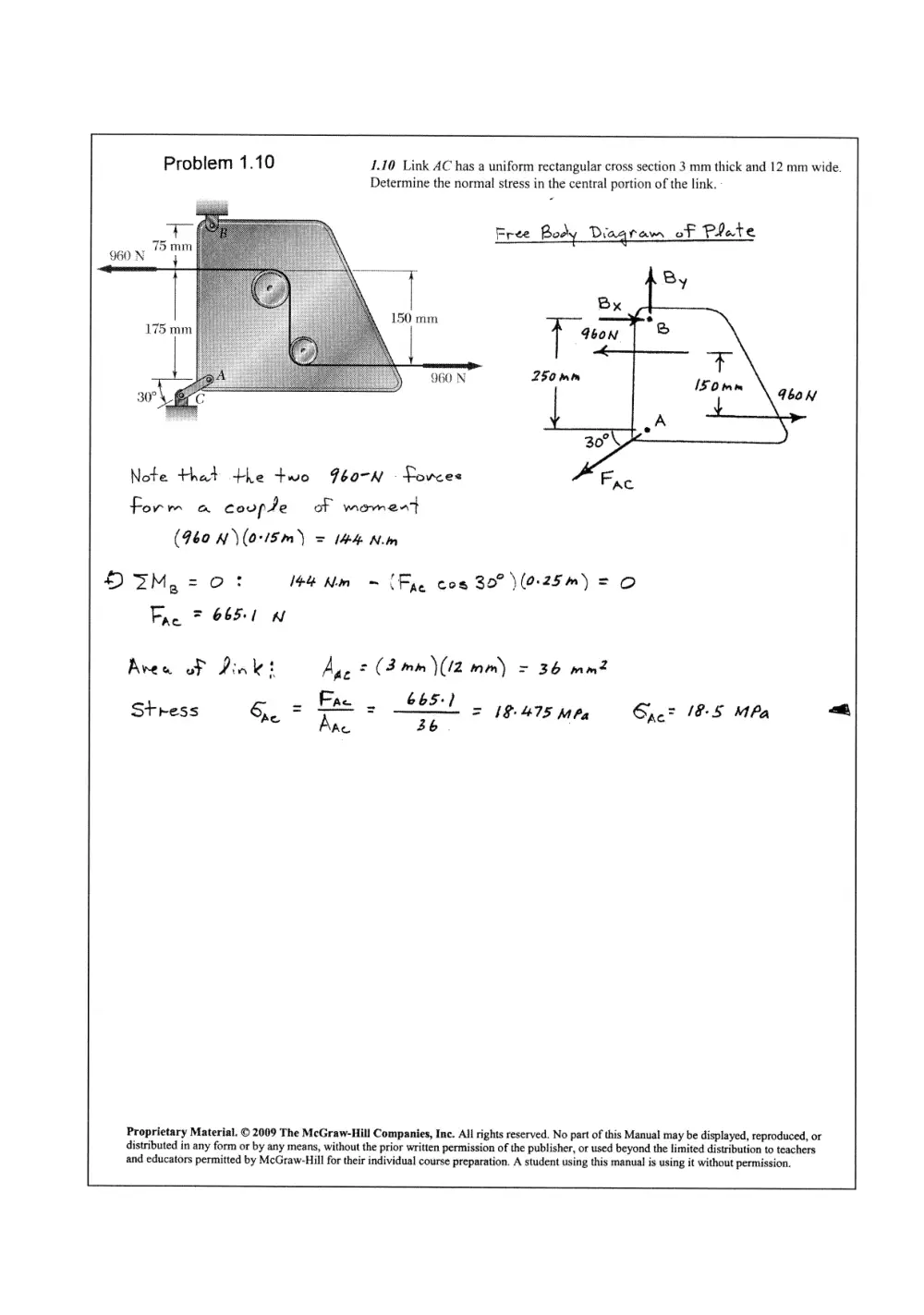
Problem 1.10 1.10 Link AC has a uniform rectangular cross section 3 mm thick and 12 mm wide.
Determine the normal stress in the central portion of the link.
Free Body Diagram of Piate
7
960 N t
ae 150 mm
175 mm |
960 N
30°
Note that the two F60-N -fovres
Form a coupte of wmenent
(960 N)\ (015m) = 144 .N.m
DIM,=0: 144 Nin ~ (Fae cog 30° (925m) = O
Fae 7 6651 W
Aven ot Dink t Aac = (3 mm \(12 mm) = 36 mmZ
< 665:
Stress Sxe = rs = —s = 18-475 MPa Sac 18:5 MPa <a
Ac
Proprietary Material. © 2009 The McGraw-Hill Companies, Inc. All rights reserved. No part of this Manual may be displayed, reproduced, or
distributed in any form or by any means, without the prior written permission of the publisher, or used beyond the limited distribution to teachers
and educators permitted by McGraw-Hill for their individual course preparation. A student using this manual is using it without permission.
P 1.7% The rigid bar EFG is supported by the truss system shown. Know-
roblem 1 11 ing that the member CG is a solid circular rod of 18 mm diameter, determine
the normal stress in CG.
Using portion EFGCB as a free body
Ht pay -o: 24 Fas -/5 =O
Fae = 25 KA
k~1.2 m—>}—1.2 m—>|<- 1.2 m—>|
Using beam EFG as a Fvee booty
Fre C
OM.s0: -Uez)et Fe + cn) (St Fd = ©
Fee = Fae = 25kW
Cross sectioned aurea of member CG
Reg = Ed? = Eloy = 2544x109 Pm
Novmal stress im CG.
F ZS mn
6 = 2! - 42 - G92 MP
“ Re. 254-Ay 9 © 4
Zz
Problem 1.12 1.12 The rigid bar EFG is supported by the truss system shown. Deter-
mine the cross-sectional area of member AE for which the normal stress in the
member is 105 MPa.
Using portion EFGCB as a Fre body
HZ Fy =o: 24 Ire ~ (=O
Fae = 2ZS5kN
Stress in meaber AE Gace = /05MPy
Fae
F, 25x / é
10 5 -b 2
Ane * a = ~L7 236/Xi10 m =m
re 05% 0
Proprietary Material. © 2009 The McGraw-Hill Companies, Inc. All rights reserved. No part of this Manual may be displayed, reproduced, or
distributed in any form or by any means, without the prior written permission of the publisher, or used beyond the limited distribution to teachers
and educators permitted by McGraw-Hill for their individual course preparation. A student using this manual is using it without permission.
Problem 1.13 1.13 A couple M of magnitude 1500 N - m is applied to the crank of an engine. For
the position shown, determine (a) the force P required to hold the engine system in
equilibrium, (b) the average normal stress in the connecting rod BC, which has a 450-
mm” uniform cross section.
P
Use piston, rod, and évank
together as free body eld
wall peaction H and beawing
peoections Ay awed Ay.
M opm 3) 2M, = O2
| (0.280 m)H - ISOO Nem = ©
60mm He 5.3571 10° N
Use piston alone as free
body. Note that yod is
a two-fovree mem ber; hence the divection
oF Force Fac is known. Draw the fovee
triangle ane sodve for Pane Fre by
proportions.
Q =.) 2Q00* + 607 = 208.81 mm
Po 202 + pe 17, 26x10? N
P= 17. 3¢ kW <=
H
Fee 2 20838) 2 pf ay
Ae = ee ae = 18.643 x/0
Rod BC is & Compression member. Tts area is 4SO mm = 4S0 x10" mn
- ~Fe _ —/8.643x/o? __ &
Stress, Ope A 7 Taso xioe Al.4xlo” Pa
(b) 6a. = - 41.4 MPa =
Proprietary Material. © 2009 The McGraw-Hill Companies, Inc. All rights reserved. No part of this Manual may be displayed, reproduced, or
distributed in any form or by any means, without the prior written permission of the publisher, or used beyond the limited distribution to teachers
and educators permitted by McGraw-Hill for their individual course preparation. A student using this manual is using it without permission.
1.14 An aircraft tow bar is positioned by means of a single hydraulic cylinder
Problem 1.14 connected by a 25-mm-diameter steel rod to two identical arm-and-wheel units DEF.
The mass of the entire tow bar is 200 kg, and its center of gravity is located at G. For
the position shown, determine the normal stress in the rod.
Dimensions in mm
—— | <->}
850 500 675 825
FREE Goby ~— ENTIRE Tow BARE
W = (200 kg)(4.8t m/st) = 1162.00 N
HVEM,= Ot
& SS50R- 150(1462.00 N) = 0
B50mm) R R= 2654.5 N
EREE Boor - Both ARM
FE wueew units: 166
tan ~& = GTS X= 8.4270°
(Fig cos XSS0) — R(Sod) = 0
S00
Fov™ 550 cos BAzTOR (2654-5 N)
2439.5 N Coome.)
500mm GTS mm w=z- Feo _ _ _2439.5,N
R=2654.5 kN co Kew (0.0125 yn)"
= - 4.9697 * 10° Po
Tz, = 4.97 MPa 4
Proprietary Material. © 2009 The McGraw-Hill Companies, Inc. All rights reserved. No part of this Manual may be displayed, reproduced, or
distributed in any form or by any means, without the prior written permission of the publisher, or used beyond the limited distribution to teachers
and educators permitted by McGraw-Hill for their individual course preparation. A student using this manual is using it without permission.