
MEE 320 Problems Chapter 1, Spring 2018
Lebanese American University · Strength of Material · 9 pages · Dr. Carine Habchi



More MEE 320 files
Show the text of this chapter
PROBLEM 1.
Two solid cylindrical rods AB and BC are welded together at B and loaded
as shown. Knowing that
1
d = 50
mm and
2
= 30
d
mm, find the average
normal stress at the midsection of (a) rod AB, (b) rod BC.
SOLUTION
(a)
Rod AB
3
2
2
3
2
3
2
1
3
6
3
40
30
70 kN
70
10 N
(50)
1.9635
10 mm
1.9635
10
m
4
4
70
10
35.7
10 Pa
1.9635
10
AB
P
A
d
P
A
π
π
σ
−
−
=
+
=
=
×
=
=
=
×
=
×
×
=
=
=
×
×
35.7 MPa
σ
AB =
(b)
Rod BC
3
2
2
2
6
2
2
3
6
6
30 kN
30
10 N
(30)
706.86 mm
706.86
10
m
4
4
30
10
42.4
10 Pa
706.86
10
π
π
σ
−
−
=
=
×
=
=
=
=
×
×
=
=
=
×
×
BC
P
A
d
P
A
42.4 MPa
σ
BC =
4
0.2 m
0.25 m
0.4 m
20 kN
C
B
A
D
E
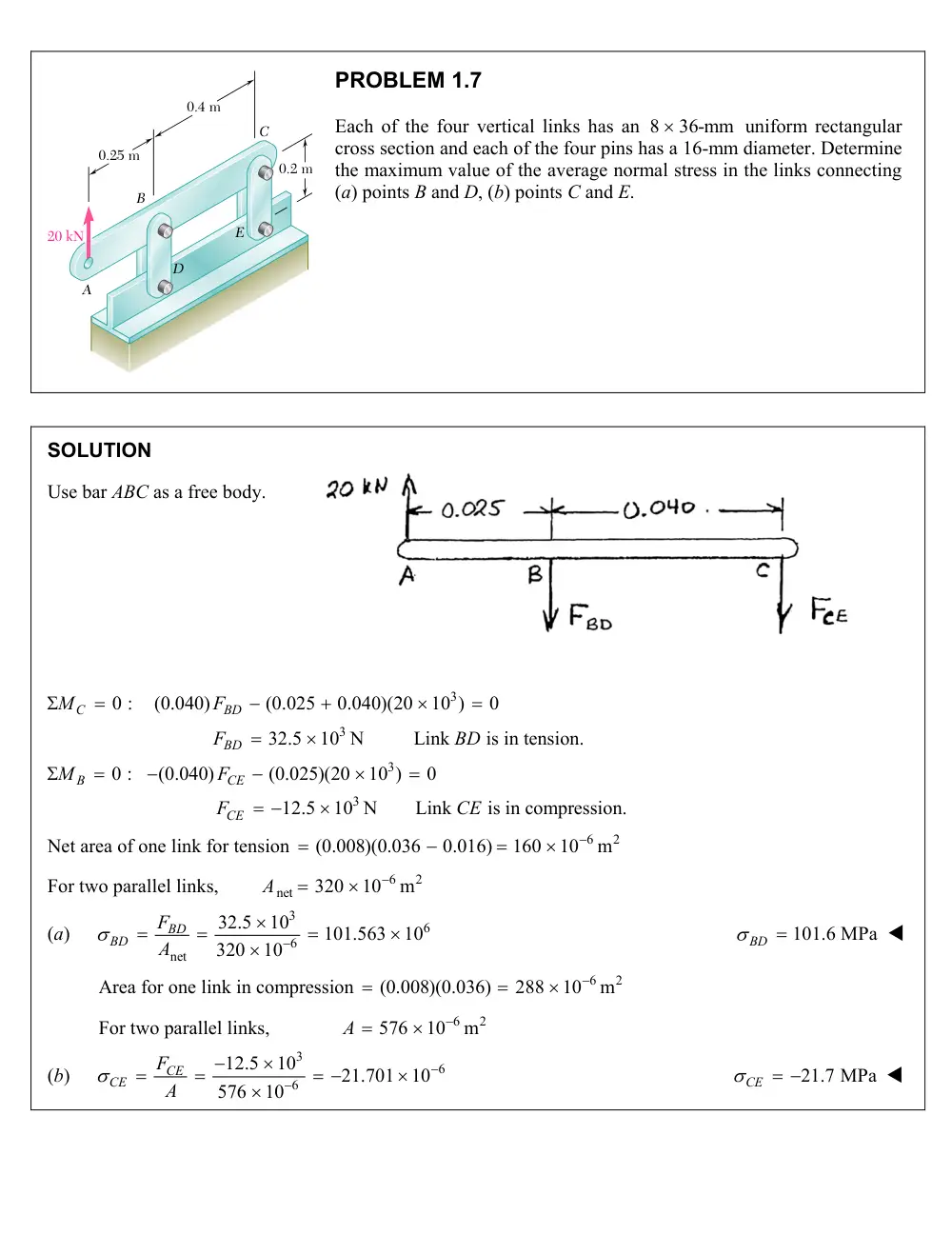
PROBLEM 1.7
Each of the four vertical links has an 8
36-mm
uniform rectangular
cross section and each of the four pins has a 16-mm diameter. Determine
the maximum value of the average normal stress in the links connecting
(a) points B and D, (b) points C and E.
SOLUTION
Use bar ABC as a free body.
3
3
3
3
0 :
(0.040)
(0.025
0.040)(20
10 )
0
32.5
10 N
Link
is in tension.
0 :
(0.040)
(0.025)(20
10 )
0
12.5
10 N
Link
is in compression.
C
BD
BD
B
CE
CE
M
F
F
BD
M
F
F
CE
Net area of one link for tension
(0.008)(0.036
0.016)
6
2
160
10
m
For two parallel links,
6
2
net
320
10
m
A
(a)
3
6
6
net
32.5
10
101.563
10
320
10
BD
BD
F
A
101.6 MPa
BD
Area for one link in compression
(0.008)(0.036)
6
2
288
10
m
For two parallel links,
6
2
576
10
m
A
(b)
3
6
6
12.5
10
21.701
10
576
10
CE
CE
F
A
21.7 MPa
CE
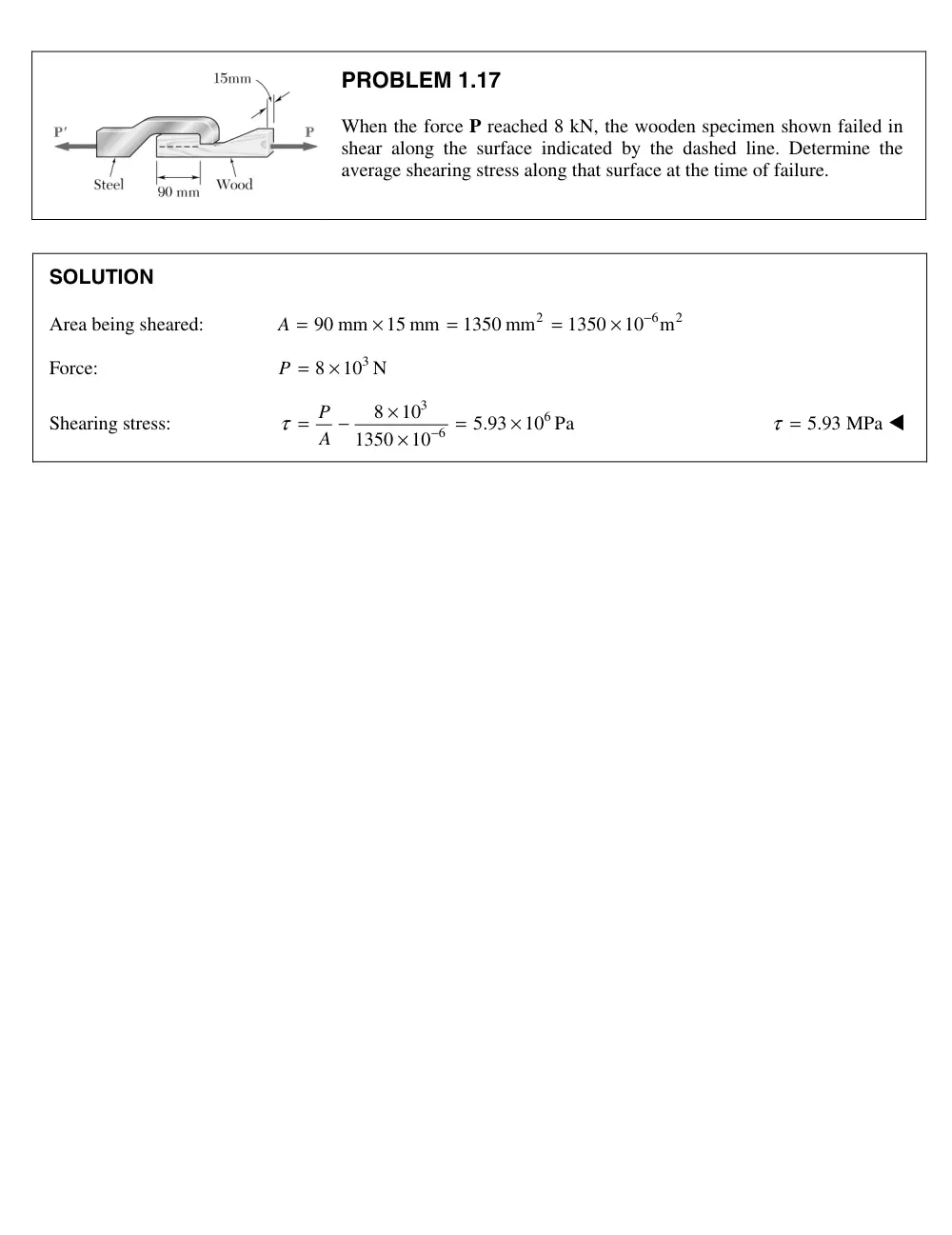
PROBLEM 1.1
When the force P reached 8 kN, the wooden specimen shown failed in
shear along the surface indicated by the dashed line. Determine the
average shearing stress along that surface at the time of failure.
SOLUTION
Area being sheared:
2
6
2
90 mm
15 mm
1350 mm
1350
10
− m
=
×
=
=
×
A
Force:
3
8
10 N
=
×
P
Shearing stress:
3
6
6
8
10
5.93
10 Pa
1350
10
τ
−
×
=
−
=
×
×
P
A
τ = 5.93 MPa
7
16 mm
750 mm
750 mm
12 mm
50 mm
B
A
C
P
�
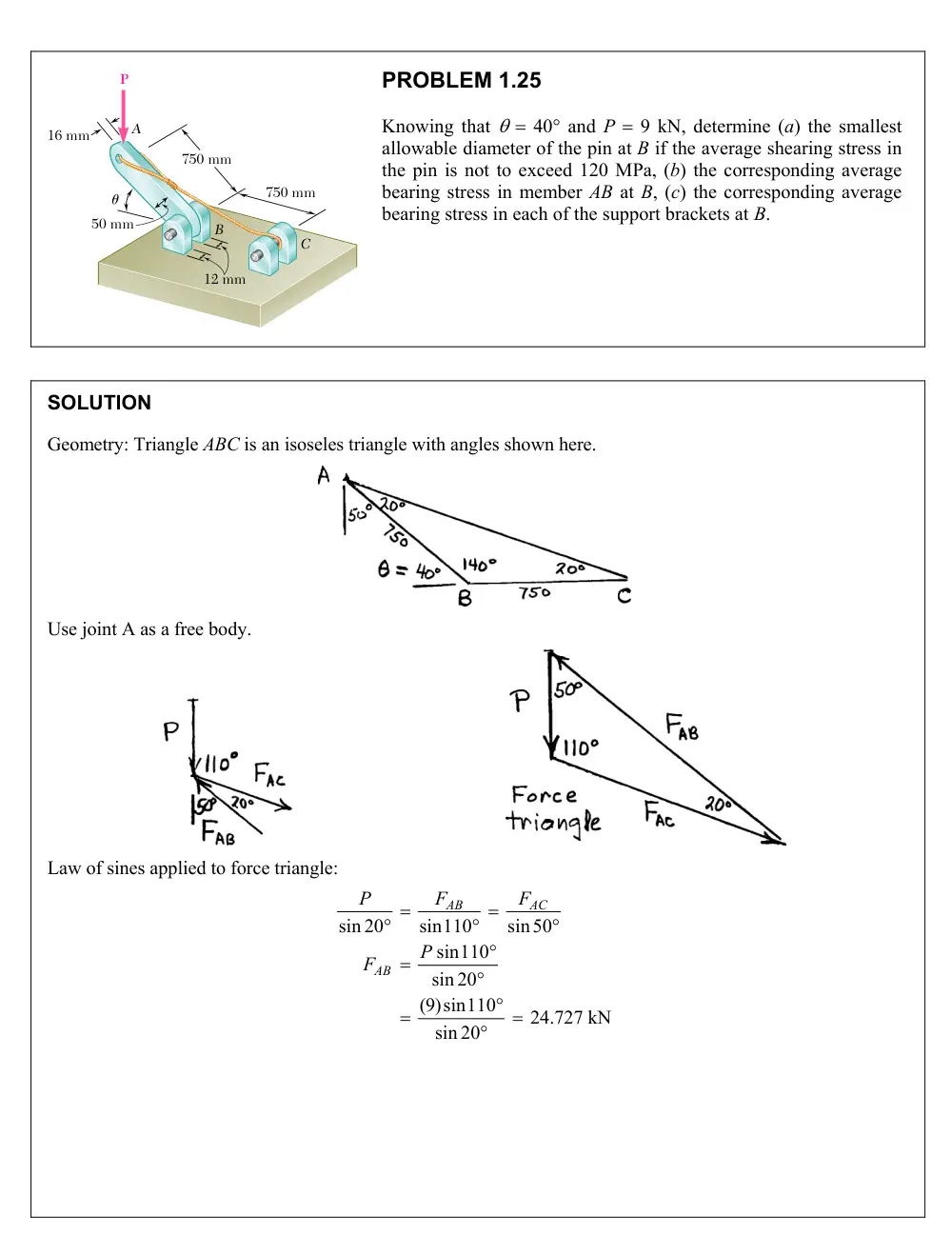
PROBLEM 1.25
Knowing that 40° and P 9 kN, determine (a) the smallest
allowable diameter of the pin at B if the average shearing stress in
the pin is not to exceed 120 MPa, (b) the corresponding average
bearing stress in member AB at B, (c) the corresponding average
bearing stress in each of the support brackets at B.
SOLUTION
Geometry: Triangle ABC is an isoseles triangle with angles shown here.
Use joint A as a free body.
Law of sines applied to force triangle:
sin 20
sin110
sin50
sin110
sin 20
(9)sin110
24.727 kN
sin 20
AB
AC
AB
P
F
F
P
F
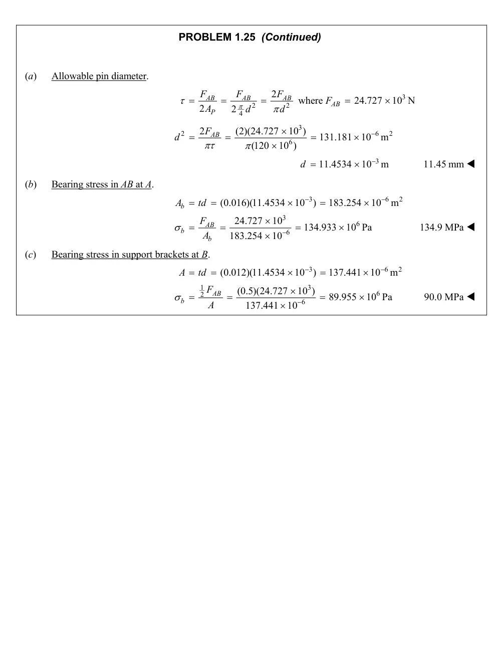
PROBLEM 1.25 (Continued)
(a)
Allowable pin diameter.
2
2
4
2
2
2
AB
AB
AB
P
F
F
F
A
d
d
where
3
24.727
10 N
FAB
3
2
6
2
6
2
(2)(24.727
10 )
131.181
10
m
(120
10 )
FAB
d
3
11.4534
10
m
d
11.45 mm
(b)
Bearing stress in AB at A.
3
6
2
3
6
6
(0.016)(11.4534
10
)
183.254
10
m
24.727
10
134.933
10 Pa
183.254
10
b
AB
b
b
A
td
F
A
134.9 MPa
(c)
Bearing stress in support brackets at B.
3
6
2
1
3
6
2
6
(0.012)(11.4534
10 )
137.441
10
m
(0.5)(24.727
10 )
89.955
10 Pa
137.441
10
AB
b
A
td
F
A
90.0 MPa
75 mm
150 mm
45
45
45
45
45
45
45
45
45
45
45
45
45
45
45
45
45
45
45
45
45
45
45
45
45�
P'
P
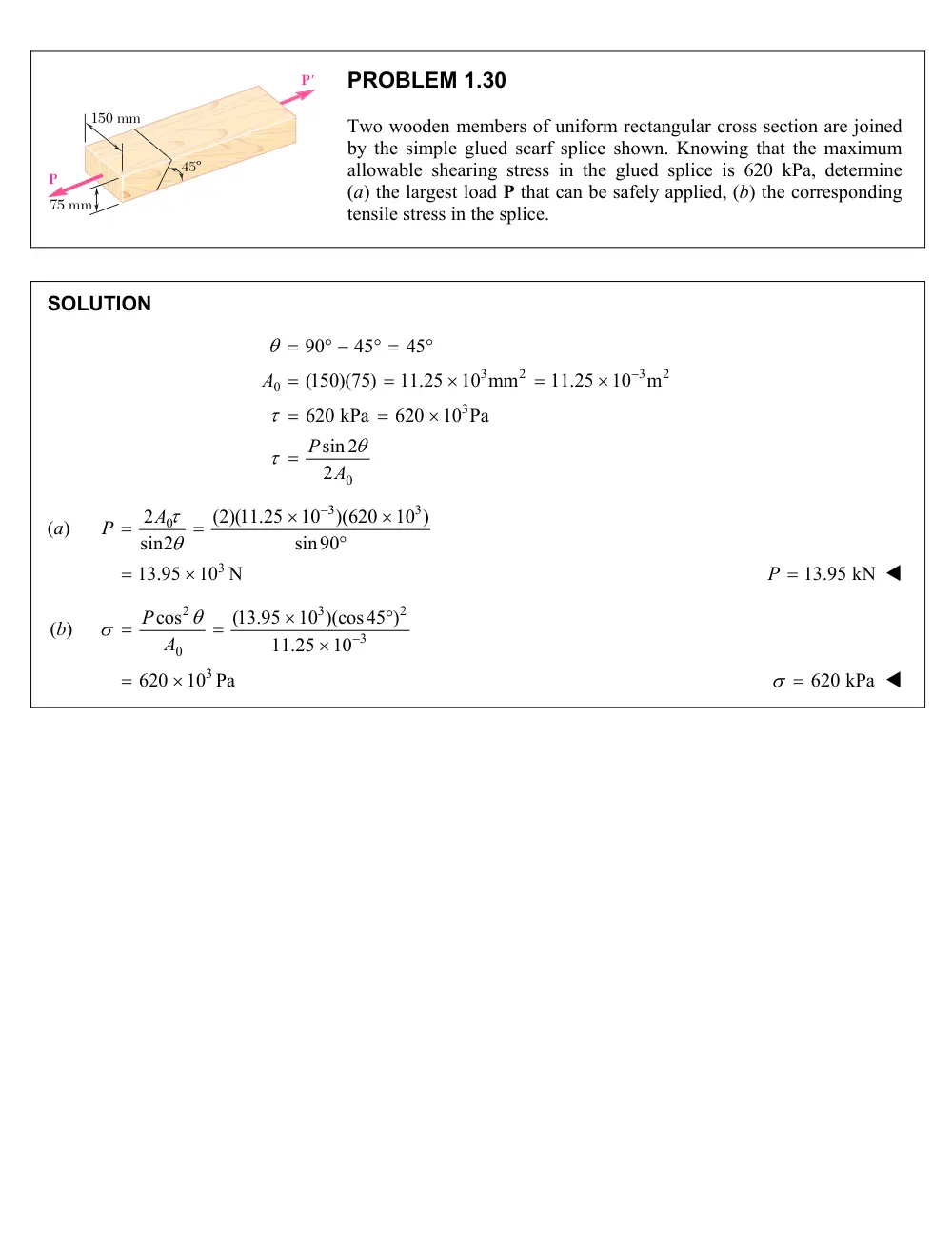
PROBLEM 1.30
Two wooden members of uniform rectangular cross section are joined
by the simple glued scarf splice shown. Knowing that the maximum
allowable shearing stress in the glued splice is 620 kPa, determine
(a) the largest load P that can be safely applied, (b) the corresponding
tensile stress in the splice.
SOLUTION
3
2
3
2
0
3
0
90
45
45
(150)(75)
11.25
10 mm
11.25
10
m
620 kPa
620
10 Pa
sin 2
2
A
P
A
(a)
3
3
2 0
(2)(11.25
10 )(620
10 )
sin2
sin90
A
P
3
13.95
10 N
P 13.95 kN
(b)
2
3
2
3
0
cos
(13.95
10 )(cos45 )
11.25
10
P
A
3
620
10 Pa
620 kPa
A
B
C
D
480 mm
908
w
P
PROBLEM 1.38
Link BC is 6 mm thick, has a width w 25 mm, and is made of a steel with
a 480-MPa ultimate strength in tension. What was the safety factor used if the
structure shown was designed to support a 16-kN load P?
SOLUTION
Use bar ACD as a free body and note that member BC is a two-force member.
3
3
0:
(480)
(600)
0
600
(600)(16
10 )
20
10 N
480
480
A
BC
BC
M
F
P
F
P
Ultimate load for member BC:
U
U
F
A
6
3
(480
10 )(0.006)(0.025)
72
10 N
FU
Factor of safety:
3
3
72
10
F.S.
20
10
U
BC
F
F
F.S.
3.60
PROBLEM 1.46
Three steel bolts are to be used to attach the steel plate shown to a wooden beam.
Knowing that the plate will support a 110-kN load, that the ultimate shearing
stress for the steel used is 360 MPa, and that a factor of safety of 3.35 is desired,
determine the required diameter of the bolts.
SOLUTION
For each bolt,
110
36.667 kN
3
=
=
P
Required:
(F.S.)
(3.35)(36.667)
122.83 kN
U
P
P
=
=
=
2
2
4
3
3
6
4
4
(4)(122.83
10 )
20.8
10
m
(360
10 )
π
τ
π
πτ
π
−
=
=
=
×
=
=
=
×
×
U
U
U
U
U
U
P
P
P
A
d
d
P
d
d = 20.8 mm
180 mm
200 mm
Top view
Side view
Front view
8 mm
20 mm
8 mm
8 mm
12 mm
12 mm
B
C
B
D
D
A
B
C
A
P
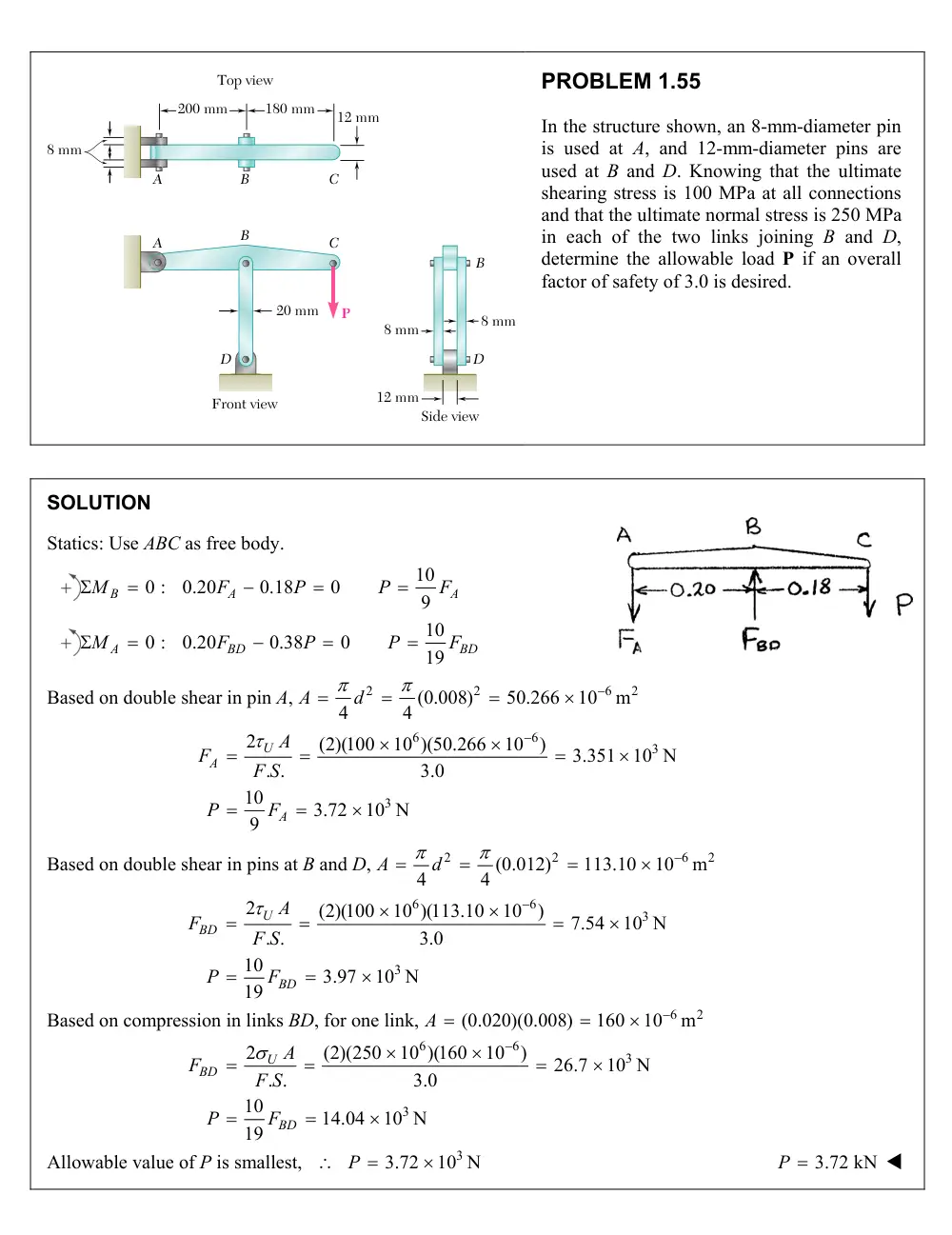
PROBLEM 1.55
In the structure shown, an 8-mm-diameter pin
is used at A, and 12-mm-diameter pins are
used at B and D. Knowing that the ultimate
shearing stress is 100 MPa at all connections
and that the ultimate normal stress is 250 MPa
in each of the two links joining B and D,
determine the allowable load P if an overall
factor of safety of 3.0 is desired.
SOLUTION
Statics: Use ABC as free body.
10
0 :
0.20
0.18
0
9
B
A
A
M
F
P
P
F
10
0 :
0.20
0.38
0
19
A
BD
BD
M
F
P
P
F
Based on double shear in pin A,
2
2
6
2
(0.008)
50.266
10
m
4
4
A
d
6
6
3
3
2
(2)(100
10 )(50.266
10
)
3.351
10 N
. .
3.0
10
3.72
10 N
9
U
A
A
A
F
F S
P
F
Based on double shear in pins at B and D,
2
2
6
2
(0.012)
113.10
10
m
4
4
A
d
6
6
3
3
2
(2)(100
10 )(113.10
10
)
7.54
10 N
. .
3.0
10
3.97
10 N
19
U
BD
BD
A
F
F S
P
F
Based on compression in links BD, for one link,
6
2
(0.020)(0.008)
160
10
m
A
6
6
3
3
2
(2)(250
10 )(160
10
)
26.7
10 N
. .
3.0
10
14.04
10 N
19
U
BD
BD
A
F
F S
P
F
Allowable value of P is smallest,
3
3.72
10 N
P
P 3.72 kN