
MEE 320 Problems Chapter 2, Spring 2018
Lebanese American University · Strength of Material · 12 pages · Dr. Carine Habchi

Showing the first 10 of 12 pages. Download the PDF to see all of it.
More MEE 320 files
Show the text of this chapter
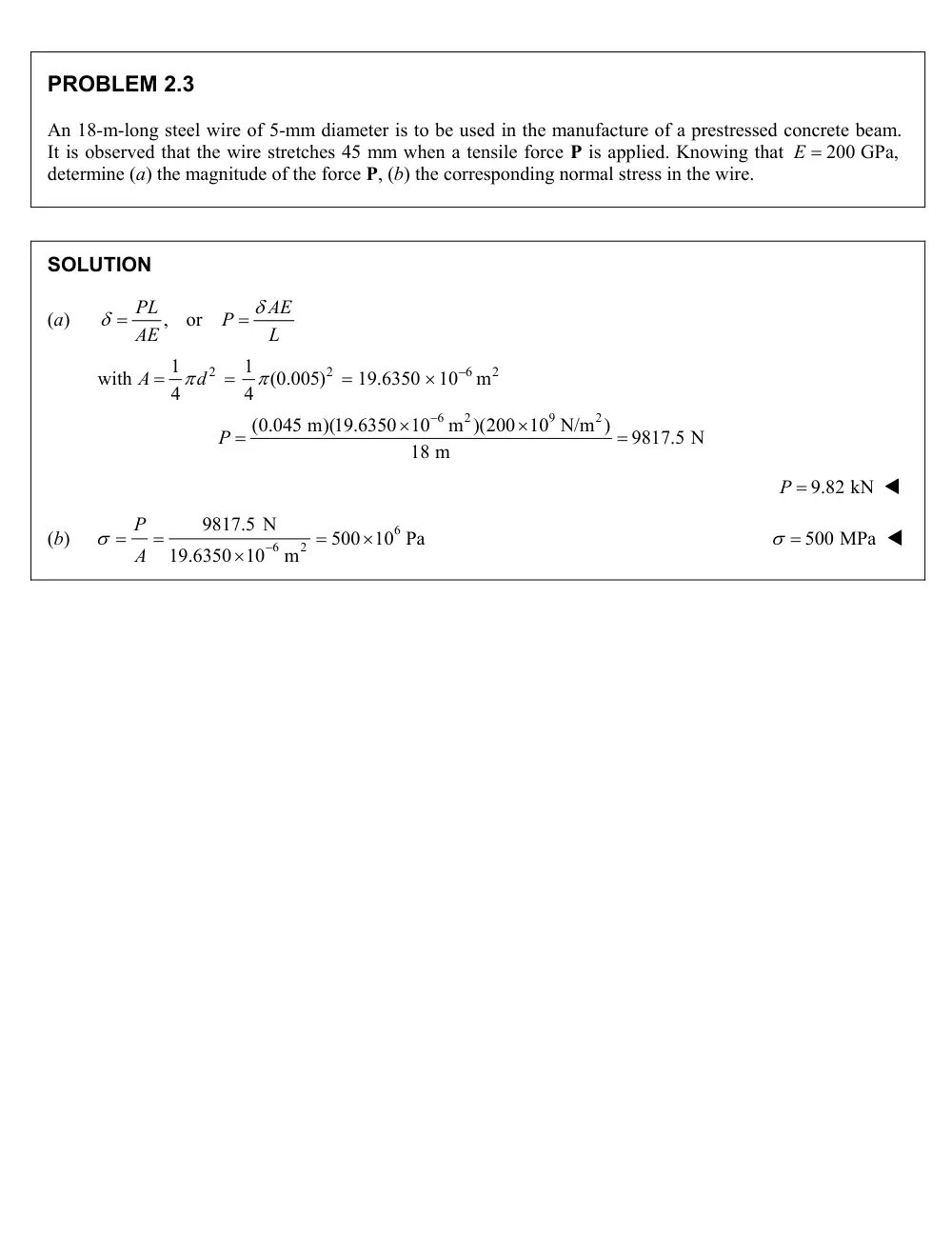
PROBLEM 2.3
An 18-m-long steel wire of 5-mm diameter is to be used in the manufacture of a prestressed concrete beam.
It is observed that the wire stretches 45 mm when a tensile force P is applied. Knowing that
E 200 GPa,
determine (a) the magnitude of the force P, (b) the corresponding normal stress in the wire.
SOLUTION
(a)
,
or
PL
AE
P
AE
L
with
2
2
6
2
1
1
(0.005)
19.6350
10
m
4
4
A
d
6
2
9
2
(0.045 m)(19.6350 10
m )(200 10 N/m )
9817.5 N
18 m
P
P 9.82 kN
(b)
6
6
2
9817.5 N
500 10 Pa
19.6350 10
m
P
A
500 MPa
PROBLEM 2.6
A control rod made of yellow brass must not stretch more than 3 mm when the tension in the wire is 4 kN.
Knowing that E = 105 GPa and that the maximum allowable normal stress is 180 MPa, determine (a) the
smallest diameter rod that should be used, (b) the corresponding maximum length of the rod.
SOLUTION
(a)
2
;
4
P
d
A
A
Substituting, we have
2
3
6
3
4
4
4(4
10 N)
(180
10 Pa)
5.3192
10
m
P
P
d
d
d
d
d 5.32 mm
(b)
;
E
L
Substituting, we have
E
E
L
L
9
3
6
(105
10 Pa)(3
10
m)
(180
10 Pa)
L
L 1.750m
0.4 m
0.5 m
P
Q
20-mm diameter
60-mm diameter
A
B
C
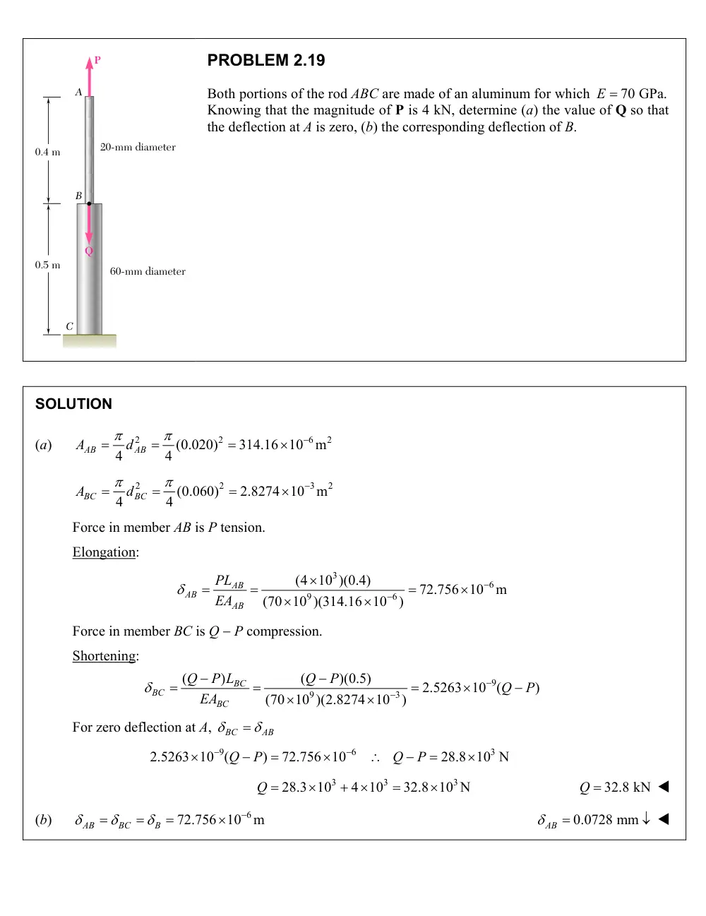
PROBLEM 2.19
Both portions of the rod ABC are made of an aluminum for which
E 70 GPa.
Knowing that the magnitude of P is 4 kN, determine (a) the value of Q so that
the deflection at A is zero, (b) the corresponding deflection of B.
SOLUTION
(a)
2
2
6
2
(0.020)
314.16 10
m
4
4
AB
AB
A
d
2
2
3
2
(0.060)
2.8274 10
m
4
4
BC
BC
A
d
Force in member AB is P tension.
Elongation:
3
6
9
6
(4 10 )(0.4)
72.756 10
m
(70 10 )(314.16 10
)
AB
AB
AB
PL
EA
Force in member BC is Q P compression.
Shortening:
9
9
3
(
)
(
)(0.5)
2.5263 10 (
)
(70 10 )(2.8274 10
)
BC
BC
BC
Q
P L
Q
P
Q
P
EA
For zero deflection at A,
BC
AB
9
6
3
2.5263 10 (
)
72.756 10
28.8 10 N
Q
P
Q
P
3
3
3
28.3 10
4 10
32.8 10 N
Q
Q 32.8 kN
(b)
72.756 10 6
m
AB
BC
B
0.0728 mm
AB
Problem 2.2
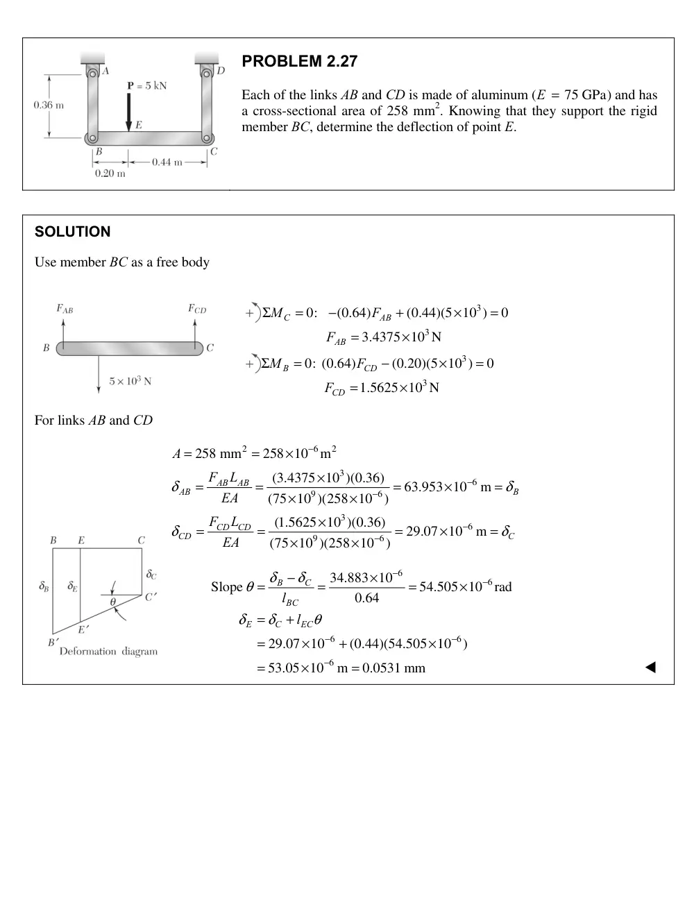
Each of the links AB and CD is made of aluminum (
E = 75 GPa)
and has
a cross-sectional area of 258 mm2. Knowing that they support the rigid
member BC, determine the deflection of point E.
Solution
Use member BC as a free body
3
3
0:
(0.64)
(0.44)(5 10 )
0
3.4375 10 N
C
AB
AB
M
F
F
Σ
=
−
+
×
=
=
×
3
3
0: (0.64)
(0.20)(5 10 )
0
1.5625 10 N
B
CD
CD
M
F
F
Σ
=
−
×
=
=
×
For links AB and CD
2
6
2
3
6
9
6
3
6
9
6
258 mm
258 10
m
(3.4375 10 )(0.36)
63.953 10
m
(75 10 )(258 10
)
(1.5625 10 )(0.36)
29.07 10
m
(75 10 )(258 10
)
AB
AB
AB
B
CD
CD
CD
C
A
F
L
EA
F
L
EA
δ
δ
δ
δ
−
−
−
−
−
=
=
×
×
=
=
=
×
=
×
×
×
=
=
=
×
=
×
×
6
6
6
6
6
34.883 10
Slope
54.505 10
rad
0.64
29.07 10
(0.44)(54.505 10
)
53.05 10
m
0.0531 mm
B
C
BC
E
C
EC
l
l
δ
δ
θ
δ
δ
θ
−
−
−
−
−
−
×
=
=
=
×
=
+
=
×
+
×
=
×
=
7
300 mm
60 mm
Aluminium shell
E � 70 GPa
Brass core
E � 105 GPa
25 mm
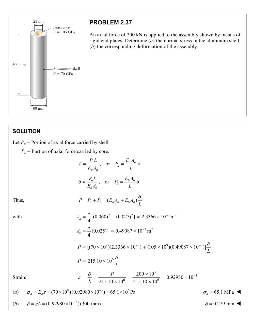
PROBLEM 2.37
An axial force of 200 kN is applied to the assembly shown by means of
rigid end plates. Determine (a) the normal stress in the aluminum shell,
(b) the corresponding deformation of the assembly.
SOLUTION
Let Pa = Portion of axial force carried by shell.
Pb = Portion of axial force carried by core.
,
or
a
a
a
a
a
a
P L
E A
P
E A
L
,
or
b
b
b
b
b
b
P L
E A
P
E A
L
Thus,
(
)
a
b
a
a
b
b
P
P
P
E A
E A
L
with
2
2
3
2
2
3
2
[(0.060)
(0.025) ]
2.3366
10
m
4
(0.025)
0.49087
10
m
4
a
b
A
A
9
3
9
3
6
[(70
10 )(2.3366
10
)
(105
10 )(0.49087
10 )]
215.10
10
P
L
P
L
Strain:
3
3
6
6
200
10
0.92980
10
215.10
10
215.10
10
P
L
(a)
9
3
6
(70 10 )(0.92980 10
)
65.1 10 Pa
a
Ea
65.1 MPa
a
(b)
(0.92980 10 3
)(300 mm)
L
0.279 mm
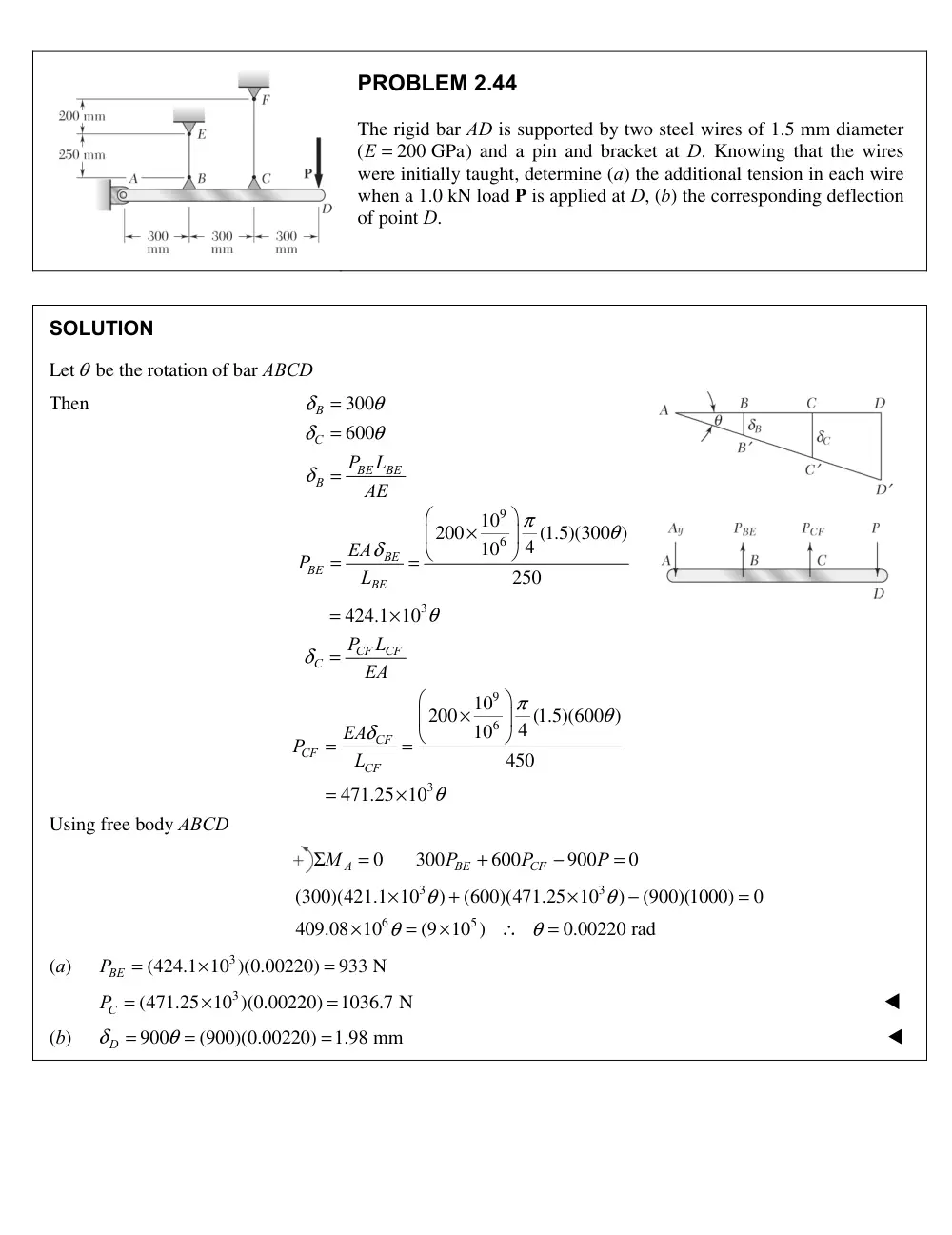
Problem 2.44
The rigid bar AD is supported by two steel wires of 1.5 mm diameter
(
E = 200 GPa)
and a pin and bracket at D. Knowing that the wires
were initially taught, determine (a) the additional tension in each wire
when a 1.0 kN load P is applied at D, (b) the corresponding deflection
of point D.
Solution
Let θ be the rotation of bar ABCD
Then
9
6
300
600
10
200
4 (1.5)(300 )
10
250
B
C
BE
BE
B
BE
BE
BE
P
L
AE
EA
P
L
δ
θ
δ
θ
δ
π
θ
δ
=
=
=
×
=
=
3
424.1 10
CF
CF
C
P
L
EA
θ
δ
=
×
=
9
6
3
10
200
4 (1.5)(600 )
10
450
471.25 10
CF
CF
CF
EA
P
L
π
θ
δ
θ
×
=
=
=
×
Using free body ABCD
0
300
600
900
0
A
BE
CF
M
P
P
P
Σ
=
+
−
=
3
3
6
5
(300)(421.1 10
)
(600)(471.25 10
)
(900)(1000)
0
409.08 10
(9 10 )
0.00220 rad
θ
θ
θ
θ
×
+
×
−
=
×
=
×
∴
=
(a)
3
(424.1 10 )(0.00220)
933 N
PBE
=
×
=
3
(471.25 10 )(0.00220)
1036.7 N
C
P =
×
=
(b)
900
(900)(0.00220)
1.98 mm
δD
θ
=
=
=
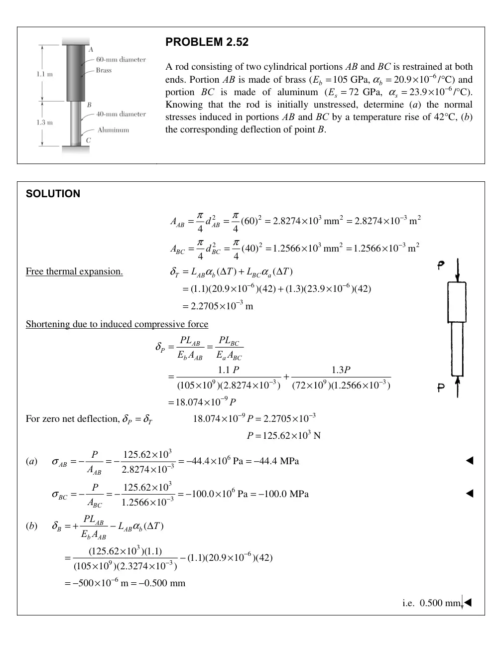
Problem 2.5
A rod consisting of two cylindrical portions AB and BC is restrained at both
ends. Portion AB is made of brass (
105 GPa,
b
E =
20.9 10 6
/ C)
αb
−
=
×
°
and
portion BC is made of aluminum (
72 GPa,
s
E =
23.9 10 6
/°C).
αs
−
=
×
Knowing that the rod is initially unstressed, determine (a) the normal
stresses induced in portions AB and BC by a temperature rise of 42°C, (b)
the corresponding deflection of point B.
Solution
2
2
3
2
3
2
2
2
3
2
3
2
(60)
2.8274 10 mm
2.8274 10
m
4
4
(40)
1.2566 10 mm
1.2566 10
m
4
4
AB
AB
BC
BC
A
d
A
d
π
π
π
π
−
−
=
=
=
×
=
×
=
=
=
×
=
×
Free thermal expansion.
6
6
3
(
)
(
)
(1.1)(20.9 10
)(42)
(1.3)(23.9 10
)(42)
2.2705 10
m
T
AB
b
BC
a
L
T
L
T
δ
α
α
−
−
−
=
Δ
+
Δ
=
×
+
×
=
×
Shortening due to induced compressive force
9
3
9
3
9
1.1
1.3
(105 10 )(2.8274 10
)
(72 10 )(1.2566 10
)
18.074 10
BC
AB
P
b
AB
a
BC
PL
PL
E A
E A
P
P
P
δ
−
−
−
=
=
=
+
×
×
×
×
=
×
For zero net deflection, P
T
δ
= δ
9
3
3
18.074 10
2.2705 10
125.62 10 N
P
P
−
−
×
=
×
=
×
(a)
3
6
3
125.62 10
44.4 10 Pa
44.4 MPa
2.8274 10
AB
AB
P
A
σ
−
×
= −
= −
= −
×
= −
×
3
6
3
125.62 10
100.0 10 Pa
100.0 MPa
1.2566 10
BC
BC
P
A
σ
−
×
= −
= −
= −
×
= −
×
(b)
3
6
9
3
6
(
)
(125.62 10 )(1.1)
(1.1)(20.9 10
)(42)
(105 10 )(2.3274 10
)
500 10
m
0.500 mm
AB
B
AB
b
b
AB
PL
L
T
E A
δ
α
−
−
−
= +
−
Δ
×
=
−
×
×
×
= −
×
= −
i.e. 0.500 mm
2
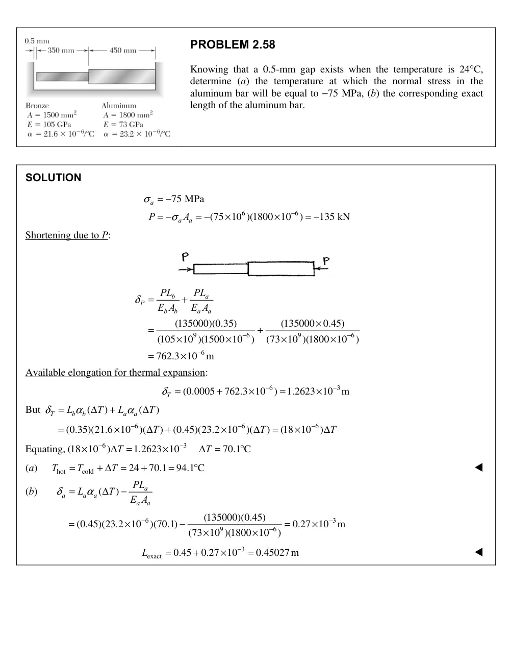
Problem 2.58
Knowing that a 0.5-mm gap exists when the temperature is 24 C,
°
determine (a) the temperature at which the normal stress in the
aluminum bar will be equal to −75 MPa, (b) the corresponding exact
length of the aluminum bar.
Solution
6
6
75 MPa
(75 10 )(1800 10
)
135 kN
a
a
a
P
A
σ
σ
−
= −
= −
= −
×
×
= −
Shortening due to P:
9
6
9
6
6
(135000)(0.35)
(135000
0.45)
(105 10 )(1500 10
)
(73 10 )(1800 10
)
762.3 10
m
b
a
P
b
b
a
a
PL
PL
E A
E A
δ
−
−
−
=
+
×
=
+
×
×
×
×
=
×
Available elongation for thermal expansion:
6
3
(0.0005
762.3 10
)
1.2623 10
m
δT
−
−
=
+
×
=
×
But
(
)
(
)
T
b
b
a
a
L
T
L
T
δ
α
α
=
Δ
+
Δ
6
6
6
(0.35)(21.6 10
)(
)
(0.45)(23.2 10
)(
)
(18 10
)
T
T
T
−
−
−
=
×
Δ
+
×
Δ
=
×
Δ
Equating,
6
3
(18 10
)
1.2623 10
70.1 C
T
T
−
−
×
Δ
=
×
Δ
=
°
(a)
hot
cold
24
70.1
94.1 C
T
T
T
=
+ Δ
=
+
=
°
(b)
(
)
a
a
a
a
a
a
PL
L
T
E A
δ
α
=
Δ
−
6
3
9
6
(135000)(0.45)
(0.45)(23.2 10
)(70.1)
0.27 10
m
(73 10 )(1800 10
)
−
−
−
=
×
−
=
×
×
×
3
exact
0.45
0.27 10
0.45027m
L
−
=
+
×
=
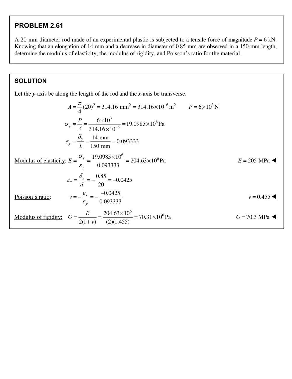
Problem 2.6
A 20-mm-diameter rod made of an experimental plastic is subjected to a tensile force of magnitude P = 6 kN.
Knowing that an elongation of 14 mm and a decrease in diameter of 0.85 mm are observed in a 150-mm length,
determine the modulus of elasticity, the modulus of rigidity, and Poisson’s ratio for the material.
Solution
Let the y-axis be along the length of the rod and the x-axis be transverse.
2
2
6
2
3
3
6
6
(20)
314.16 mm
314.16 10
m
6 10 N
4
6 10
19.0985 10 Pa
314.16 10
14 mm
0.093333
150 mm
y
y
y
A
P
P
A
L
π
σ
δ
ε
−
−
=
=
=
×
=
×
×
=
=
=
×
×
=
=
=
Modulus of elasticity:
6
6
19.0985 10
204.63 10 Pa
0.093333
y
y
E
σ
ε
×
=
=
=
×
E = 205 MPa
0.85
0.0425
20
x
x
d
ε = δ
= −
= −
Poisson’s ratio:
0.0425
0.093333
x
y
v
ε
ε
−
= −
= −
v = 0.455
Modulus of rigidity:
6
6
204.63 10
70.31 10 Pa
2(1
)
(2)(1.455)
E
G
v
×
=
=
=
×
+
G = 70.3 MPa
1
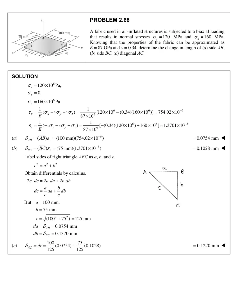
Problem 2.
A fabric used in air-inflated structures is subjected to a biaxial loading
that results in normal stresses
120
x
σ =
MPa and
160
z
σ =
MPa.
Knowing that the properties of the fabric can be approximated as
E = 87 GPa and v = 0.34, determine the change in length of (a) side AB,
(b) side BC, (c) diagonal AC.
Solution
6
6
6
6
6
9
6
6
3
9
120 10 Pa,
0,
160 10 Pa
1
1
(
)
[120 10
(0.34)(160 10 )]
754.02 10
87 10
1
1
(
)
[ (0.34)(120 10 )
160 10 ]
1.3701 10
87 10
σ
σ
σ
ε
σ
σ
σ
ε
σ
σ
σ
−
−
=
×
=
=
×
=
−
−
=
×
−
×
=
×
×
=
−
−
+
=
−
×
+
×
=
×
×
x
y
z
x
x
y
z
z
x
y
z
v
v
E
v
v
E
(a)
6
(
)
(100 mm)(754.02 10
)
δ
ε
−
=
=
×
AB
x
AB
= 0.0754 mm
(b)
6
(
)
(75 mm)(1.3701 10
)
δ
ε
−
=
=
×
BC
z
BC
= 0.1028 mm
Label sides of right triangle ABC as a, b, and c.
2
2
2
c
a
b
=
+
Obtain differentials by calculus.
2
2
2
=
+
=
+
c dc
a da
b db
a
b
dc
da
db
c
c
But
2
2
100 mm,
75 mm,
(100
75 )
125 mm
0.0754 mm
0.1370 mm
δ
δ
=
=
=
+
=
=
=
=
=
AB
BC
a
b
c
da
db
(c)
100
75
(0.0754)
(0.1028)
125
125
δ
=
=
+
AC
dc
= 0.1220 mm
68
200 mm
b
a
P
PROBLEM 2.79
2.
An elastomeric bearing (G = 0.9 MPa) is used to support a
bridge girder as shown to provide flexibility during
earthquakes. The beam must not displace more than 10 mm
when a 22 kN lateral load is applied as shown. Determine
(a) the smallest allowable dimension b, (b) the smallest
required thickness a if the maximum allowable shearing
stress is 420 kPa.
SOLUTION
Shearing force
P = 22 ¥ 103 N
Shearing stress
t = 420 ¥ 103 Pa
t = P
A
\
A = P
t = 22
10
420
10
3
3
¥
¥
= 52.381 ¥ 10–3 m2
= 52.381 ¥ 103 mm2
A = (200 mm) (b)
b = A
200 = 52 381
10
200
3
.
¥
= 262 mm
g = t
G = 420
10
0 9
10
3
6
¥
¥
.
= 466.67 ¥ 10–3
But
g = d
a
\
a = d
g =
10 mm
466.67
¥ 10 3
- = 21.4 mm
PROBLEM 2.80
2.8
For the elastomeric bearing in Prob. 2.81 with b = 220 mm
and a = 30 mm, determine the shearing modulus G and the
shear stress t for a maximum lateral load P = 19 kN and a
maximum displacement d = 12 mm.
SOLUTION
Shearing force
P = 19 ¥ 103 N
Area
A = (200 mm)(220 mm) = 44 ¥ 103 mm2
= 44 ¥ 10–3 m2
d
P
P
a
200 mm
b
a
P
79
0
rA 5 20 mm
rB 5 15 mm
B
A
64 mm
88 mm
P
t
PROBLEM 2.98
For
P 100 kN,
determine the minimum plate thickness t required if the
allowable stress is 125 MPa.
SOLUTION
At the hole:
20 mm
88
40
48 mm
A
A
r
d
2
2(20)
0.455
88
A
A
r
D
From Fig. 2.60a,
K 2.20
max
net
max
3
3
6
(2.20)(100
10 N)
36.7
10
m
36.7 mm
(0.048 m)(125
10 Pa)
A
A
KP
KP
KP
t
A
d t
d
t
At the fillet:
88
88 mm,
64 mm
1.375
64
B
B
D
D
d
d
15
15 mm
0.2344
64
B
B
B
r
r
d
From Fig. 2.60b,
K 1.70
max
min
B
KP
KP
A
d t
3
3
6
max
(1.70)(100
10 N)
21.25
10
m
21.25 mm
(0.064 m)(125
10 Pa)
B
KP
t
d
The larger value is the required minimum plate thickness.
t 36.7 mm