
MEE 320 Problems Chapter 3, Spring 2018
Lebanese American University · Strength of Material · 11 pages · Dr. Carine Habchi



Showing the first 10 of 11 pages. Download the PDF to see all of it.
More MEE 320 files
Show the text of this chapter
T
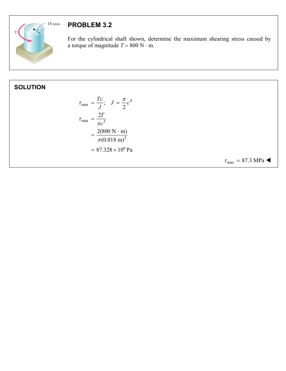
18 mm
PROBLEM 3.2
For the cylindrical shaft shown, determine the maximum shearing stress caused by
a torque of magnitude T 800 N m.
SOLUTION
4
max
max
3
3
6
;
2
2
2(800 N m)
(0.018 m)
87.328
10 Pa
Tc
J
c
J
T
c
max
87.3 MPa
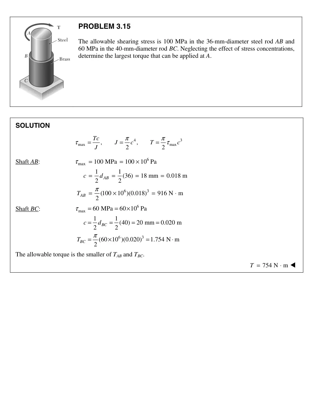
PROBLEM 3.1
The allowable shearing stress is 100 MPa in the 36-mm-diameter steel rod AB and
60 MPa in the 40-mm-diameter rod BC. Neglecting the effect of stress concentrations,
determine the largest torque that can be applied at A.
SOLUTION
4
3
max
max
,
,
2
2
Tc
J
c
T
c
J
π
π
τ
τ
=
=
=
Shaft AB:
6
max
6
3
100 MPa
100
10 Pa
1
1 (36)
18 mm
0.018 m
2
2
(100
10 )(0.018)
916 N m
2
AB
AB
c
d
T
τ
π
=
=
×
=
=
=
=
=
×
=
⋅
Shaft BC:
6
max
6
3
60 MPa
60 10 Pa
1
1 (40)
20 mm
0.020 m
2
2
(60 10 )(0.020)
1.754 N m
2
BC
BC
c
d
T
τ
π
=
=
×
=
=
=
=
=
×
=
⋅
The allowable torque is the smaller of TAB and TBC.
754 N
m
T =
⋅
5
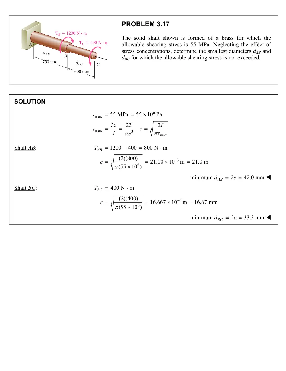
750 mm
600 mm
TB � 1200 N · m
TC � 400 N · m
dAB
B
A
C
dBC
PROBLEM 3.17
The solid shaft shown is formed of a brass for which the
allowable shearing stress is 55 MPa. Neglecting the effect of
stress concentrations, determine the smallest diameters dAB and
dBC for which the allowable shearing stress is not exceeded.
SOLUTION
6
max
3
max
3
max
55 MPa
55
10 Pa
2
2
Tc
T
T
c
J
c
Shaft AB:
3
3
6
1200
400
800 N m
(2)(800)
21.00
10
m
21.0 m
(55
10 )
AB
T
c
minimum
2
42.0 mm
dAB
c
Shaft BC:
3
3
6
400 N m
(2)(400)
16.667
10
m
16.67 mm
(55
10 )
BC
T
c
minimum
2
33.3 mm
dBC
c
A
100 mm
40 mm
C
B
D
T � 1000 N · m
PROBLEM 3.21
A torque of magnitude
T 1000 N m
is applied
at D as shown. Knowing that the allowable
shearing stress is 60 MPa in each shaft, determine
the required diameter of (a) shaft AB, (b) shaft CD.
SOLUTION
1000 N m
100 (1000)
2500 N m
40
CD
B
AB
CD
C
T
r
T
T
r
(a)
Shaft AB:
6
all
3
6
3
3
6
60
10 Pa
2
2
(2)(2500)
26.526
10
m
(60
10 )
Tc
T
T
c
J
c
3
29.82
10
29.82 mm
c
2 = 59.6 mm
d
c
(b)
Shaft CD:
6
all
3
6
3
3
6
60
10 Pa
2
2
(2)(1000)
10.610
10
m
(60
10 )
Tc
T
T
c
J
c
3
21.97
10
m
21.97 mm
c
2 = 43.9 mm
d
c
2.5 m
40 mm
50 mm
A
B
T0
PROBLEM 3.34
(a) For the aluminum pipe shown (G 27 GPa), determine the torque T0
causing an angle of twist of 2°. (b) Determine the angle of twist if the
same torque T0 is applied to a solid cylindrical shaft of the same length
and cross-sectional area.
SOLUTION
(a)
4
4
4
4
6
4
3
9
50 mm
0.050 m,
40 mm
0.040 m
(
)
(0.050
0.040 )
2
2
5.7962
10
m
2
34.907
10
rad
2.5 m
27
10 Pa
o
i
o
i
c
c
J
c
c
L
G
TL
GJ
9
6
3
0
3
(27
10 )(5.7962
10
)(34.907
10 )
2.5
2.1851
10 N m
GJ
T
L
0
T 2.19 kN m
Area of pipe:
2
2
2
2
2
(
)
(0.050
0.040 )
2.8274 m
o
i
A
c
c
(b)
Radius of solid of same area:
4
4
6
2
3
0
9
6
0.030 m
(0.030)
1.27235
10
m
2
2
(2.1851
10 )(2.5)
0.15902 rad
(27
10 )(1.27235
10
)
s
s
s
s
A
c
J
c
T L
GJ
9.11
s
400 mm
375 mm
250 mm
D
60 mm
36 mm
TA � 800 N · m
TB � 1600 N · m
C
B
A
PROBLEM 3.38
The aluminum rod AB (
G 27 GPa)
is bonded to the brass
rod BD (
G 39 GPa).
Knowing that portion CD of the
brass rod is hollow and has an inner diameter of 40 mm,
determine the angle of twist at A.
SOLUTION
Rod AB:
9
4
4
9
3
/
9
9
27
10 Pa,
0.400 m
1
800N m
0.018 m
2
(0.018)
164.896
10
m
2
2
(800)(0.400)
71.875
10
rad
(27
10 )(164.896
10
)
A B
G
L
T
c
d
J
c
TL
GJ
Part BC:
9
4
4
6
4
3
/
9
6
1
39
10 Pa
0.375 m,
0.030 m
2
800
1600
2400 N m,
(0.030)
1.27234
10
m
2
2
(2400)(0.375)
18.137
10
rad
(39
10 )(1.27234
10
)
B C
G
L
c
d
T
J
c
TL
GJ
Part CD:
1
1
2
2
4
4
4
4
6
4
2
1
3
/
9
6
1
0.020 m
2
1
0.030 m,
0.250 m
2
(0.030
0.020 )
1.02102
10
m
2
2
(2400)(0.250)
15.068
10
rad
(39
10 )(1.02102
10
)
C D
c
d
c
d
L
J
c
c
TL
GJ
Angle of twist at A.
/
/
/
3
105.080
10
rad
A
A B
B C
C D
6.02
A
PROBLEM 3.41
Two shafts, each of 22-mm diameter are
connected by the gears shown. Knowing that
G = 77 GPa
and that the shaft at F is fixed,
determine the angle through which end A rotates
when a 130 N ⋅ m torque is applied at A.
SOLUTION
Calculation of torques.
Circumferential contact force between gears B and E.
AB
EF
E
EF
AB
B
E
B
T
T
r
F
T
T
r
r
r
=
=
=
130 N m
150 (130)
177.3 N m
110
AB
EF
T
T
=
⋅
=
=
⋅
Twist in shaft FE.
4
4
9
4
/
9
9
1
300 mm,
11 mm,
776 Pa
2
(0.011)
23
10
m
2
2
(177.3)(0.3)
0.03 rad
(77
10 )(23
10
)
E F
L
c
d
G
J
c
TL
GJ
π
π
ϕ
−
−
=
=
=
=
=
=
=
×
=
=
=
×
×
Rotation at E.
/
0.03 rad
E F
ϕE
= ϕ
=
Tangential displacement at gear circle
E
E
B
B
r
r
δ
ϕ
ϕ
=
=
Rotation at B.
15 (0.03)
0.0409 rad
11
E
B
E
B
r
r
ϕ
ϕ
=
=
=
Twist in shaft BA.
9
4
/
9
9
0.35 m
23
10
m
(130)(0.35)
0.0257 rad
(77
10 )(23
10
)
A B
L
J
TL
GJ
ϕ
−
−
=
=
×
=
=
=
×
×
Rotation at A.
/
0.0666 rad
A
B
A B
ϕ
ϕ
ϕ
=
+
=
3.82
ϕA
=
°
PROBLEM 3.53
The composite shaft shown consists of a 5 mm thick brass jacket
(G = 39 GPa) bonded to a 30 mm diameter steel core (G = 77 GPa).
Knowing that the shaft is subjected to 565 N ⋅ m torques, determine
(a) the maximum shearing stress in the brass jacket, (b) the
maximum shearing stress in the steel core, (c) the angle of twist of
end B relative to end A.
SOLUTION
Steel core:
1
4
4
9
4
1
1
9
9
2
1 1
1
15 mm
2
(0.015)
79.52
10
m
2
2
(77
10 )(79.52
10
)
6123.04 N m
c
d
J
c
G J
π
π
−
−
=
=
=
=
=
×
=
×
×
=
⋅
Torque carried by steel core
1
1 1
T
G J L
ϕ
=
Brass jacket:
(
)
2
1
4
4
4
4
6
4
2
2
1
9
6
2
2
2
15 mm
5 mm
20 mm
(0.02
0.015 )
0.1718 10
m
2
2
(39 10 )(0.1718 10
)
6700.4 N m
c
c
t
J
c
c
G J
π
π
−
−
=
+ =
+
=
=
−
=
−
=
×
=
×
×
=
⋅
Torque carried by brass jacket
2
2
2
T
G J L
ϕ
=
Total torque
1
2
1 1
2
2
1 1
2
2
(
)
565
0.044 rad/m
6123.04
6700.4
T
T
T
G J
G J
L
T
L
G J
G J
ϕ
ϕ
=
+
=
+
=
=
=
+
+
(a)
Maximum shearing stress in brass jacket
9
max
2 max
2
2
(39
10 )(0.02)(0.044)
G
G C L
ϕ
τ
γ
=
=
=
×
6
2
34.37
10 N/m
=
×
34.37 MPa
(b)
Maximum shearing stress in steel core
9
max
1 max
1 1
(77
10 )(0.015)(0.044)
G
G C L
ϕ
τ
γ
=
=
=
×
6
2
50.82
10 N/m
=
×
50.82 MPa
(c)
Angle of twist (L = 1.8 m)
3
(1.8)(0.044)
79.2
10
rad
L L
ϕ
ϕ
−
=
=
=
×
= 4.53°
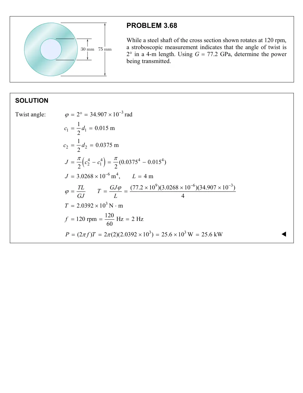
75 mm
30 mm
PROBLEM 3.68
While a steel shaft of the cross section shown rotates at 120 rpm,
a stroboscopic measurement indicates that the angle of twist is
2° in a 4-m length. Using G 77.2 GPa, determine the power
being transmitted.
SOLUTION
Twist angle:
3
1
1
2
2
4
4
4
4
2
1
6
4
2
34.907
10
rad
1
0.015 m
2
1
0.0375 m
2
(0.0375
0.015 )
2
2
3.0268
10
m ,
4 m
c
d
c
d
J
c
c
J
L
9
6
3
3
(77.2
10 )(3.0268
10
)(34.907
10
)
4
2.0392
10 N m
120
120 rpm
Hz
2 Hz
60
TL
GJ
T
GJ
L
T
f
3
3
(2
)
2 (2)(2.0392
10 )
25.6
10 W
25.6 kW
P
f T
60 mm
30 mm
T
T'
PROBLEM 3.87
The stepped shaft shown must rotate at a frequency of 50 Hz. Knowing
that the radius of the fillet is
r 8
mm and the allowable shearing stress
is 45 MPa, determine the maximum power that can be transmitted.
SOLUTION
3
3
3
2
2
1
30 mm
15 mm
15
10
m
2
60 mm,
8 mm
60
8
2,
0.26667
30
30
KTc
KT
c
T
J
K
c
d
c
d
D
r
D
r
d
d
From Fig. 3.32,
K 1.18
Allowable torque.
3 3
6
(15
10 ) (45
10 )
202.17 N m
(2)(1.18)
T
Maximum power.
3
2
(2 )(50)(202.17)
63.5
10 W
P
f T
P 63.5 kW