
MEE 320 Problems Chapter 4, Spring 2018
Lebanese American University · Strength of Material · 10 pages · Dr. Carine Habchi




More MEE 320 files
Show the text of this chapter
M 5 15 kN · m
Dimensions in mm
B
20
40
20
20
20
80
A
PROBLEM 4.1
Knowing that the couple shown acts in a vertical plane, determine
the stress at (a) point A, (b) point B.
SOLUTION
For rectangle:
3
1
12
I
bh
Outside rectangle:
3
1
1 (80)(120)
I 12
6
4
6
4
1
11.52
10 mm
11.52
10
m
I
Cutout:
3
2
1 (40)(80)
12
I
6
4
6
4
2
1.70667
10 mm
1.70667
10
m
I
Section:
6
4
1
2
9.81333
10
m
I
I
I
(a)
40 mm
0.040 m
yA
3
6
6
(15
10 )(0.040)
61.6
10 Pa
9.81333
10
A
A
My
I
61.6 MPa
A
(b)
60 mm
0.060 m
yB
3
6
6
(15
10 )( 0.060)
91.7
10 Pa
9.81333
10
B
B
My
I
91.7 MPa
B
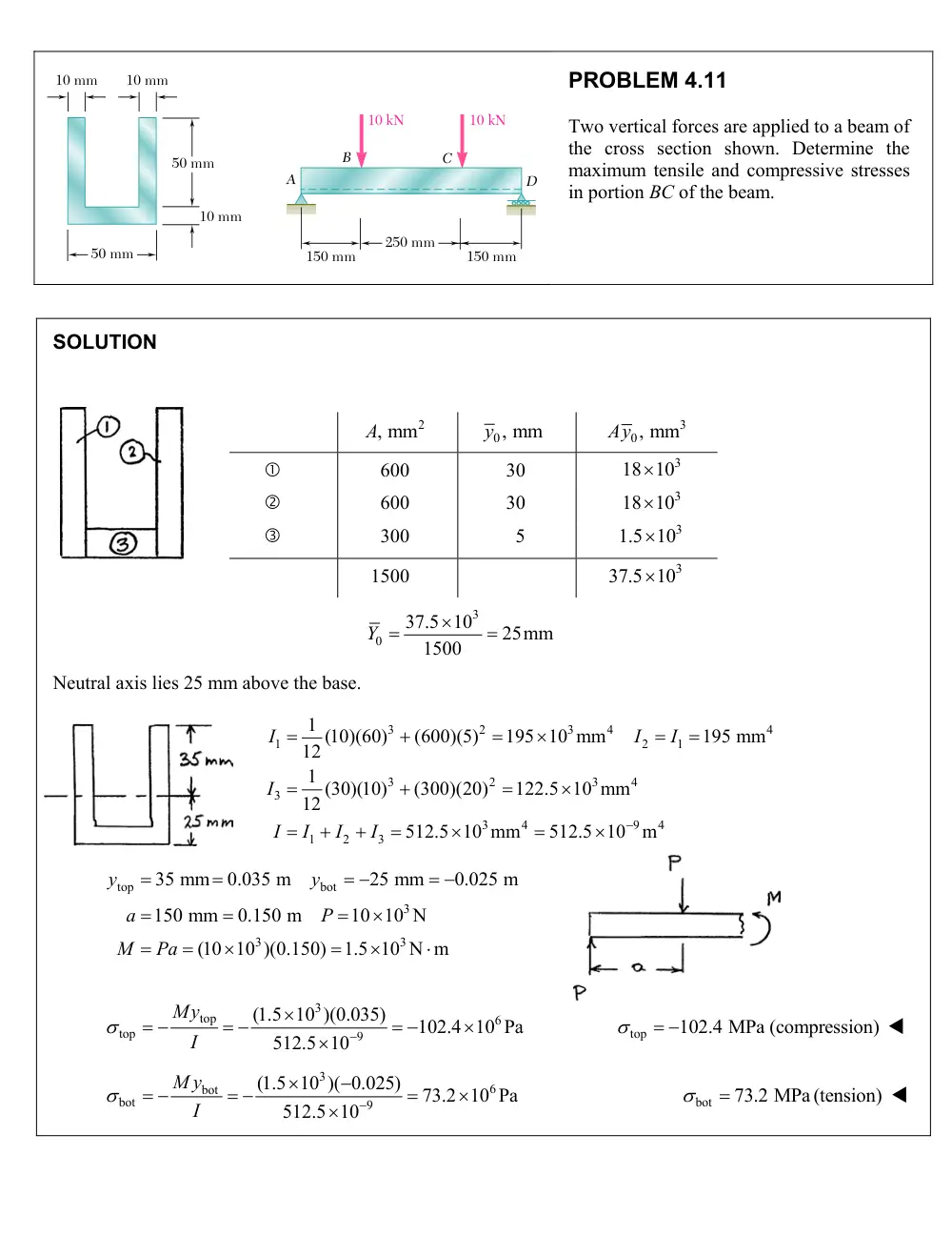
10 mm
10 mm
50 mm
10 mm
150 mm
150 mm
A
D
B
C
10 kN
10 kN
250 mm
50 mm
PROBLEM 4.11
Two vertical forces are applied to a beam of
the cross section shown. Determine the
maximum tensile and compressive stresses
in portion BC of the beam.
SOLUTION
A, mm2
y0, mm
Ay0, mm3
600
30
18 103
600
30
18 103
300
5
1.5 103
1500
37.5 103
3
0
37.5 10
25mm
1500
Y
Neutral axis lies 25 mm above the base.
3
2
3
4
4
1
2
1
3
2
3
4
3
3
4
9
4
1
2
3
1 (10)(60)
(600)(5)
195 10 mm
195 mm
12
1 (30)(10)
(300)(20)
122.5 10 mm
12
512.5 10 mm
512.5 10
m
I
I
I
I
I
I
I
I
top
bot
3
3
3
35 mm
0.035 m
25 mm
0.025 m
150 mm
0.150 m
10 10 N
(10 10 )(0.150)
1.5 10 N m
y
y
a
P
M
Pa
3
top
6
top
9
(1.5 10 )(0.035)
102.4 10 Pa
512.5 10
My
I
top
102.4 MPa (compression)
3
6
bot
bot
9
(1.5 10 )( 0.025)
73.2 10 Pa
512.5 10
M y
I
bot
73.2 MPa (tension)
54 mm
40 mm
80 mm
M
PROBLEM 4.19
Knowing that for the extruded beam shown the allowable stress is
120 MPa in tension and 150 MPa in compression, determine the largest
couple M that can be applied.
SOLUTION
A, mm2
y0, mm
Ay0, mm3
d, mm
2160
27
58,320
3
1080
36
38,880
3
Σ
3240
97,200
97,200
30 mm
The neutral axis lies 30 mm above the bottom.
3240
Y
top
bot
3
2
3
2
3
4
1
1 1
1 1
2
2
3
2
3
4
2
2 2
2
2
3
4
9
4
1
2
54
30
24 mm
0.024 m
30 mm
0.030 m
1
1 (40)(54)
(40)(54)(3)
544.32 10 mm
12
12
1
1
1
(40)(54)
(40)(54)(6)
213.84 10 mm
36
36
2
758.16 10 mm
758.16 10
m
y
y
I
b h
A d
I
b h
A d
I
I
I
|
|
|
|
M y
I
M
I
y
Top: (tension side)
6
9
3
(120 10 )(758.16 10
)
3.7908 10 N m
0.024
M
Bottom: (compression)
6
9
3
(150 10 )(758.16 10
)
3.7908 10 N m
0.030
M
Choose the smaller as Mall.
3
all
3.7908 10 N m
M
all
3.79 kN m
M
20 mm
12 mm
60 N · m
z
y
PROBLEM 4.24
A 60-N m couple is applied to the steel bar shown. (a) Assuming that
the couple is applied about the z axis as shown, determine the maximum
stress and the radius of curvature of the bar. (b) Solve part a, assuming
that the couple is applied about the y axis. Use
E 200 GPa.
SOLUTION
(a)
Bending about z-axis.
3
3
3
4
9
4
1
1 (12)(20)
8 10 mm
8 10
m
12
12
20
10 mm
0.010 m
2
I
bh
c
6
9
(60)(0.010)
75.0 10 Pa
8 10
Mc
I
75.0 MPa
3
1
9
9
1
60
37.5 10
m
(200 10 )(8 10
)
M
EI
26.7 m
(b)
Bending about y-axis.
3
3
3
4
9
4
6
9
1
1 (20)(12)
2.88 10 mm
2.88 10
m
12
12
12
6 mm
0.006 m
2
(60)(0.006)
125.0 10 Pa
2.88 10
I
bh
c
Mc
I
125.0 MPa
3
1
9
9
1
60
104.17 10
m
(200 10 )(2.88 10
)
M
EI
9.60 m
z
x
y
C
A
M
PROBLEM 4.31
A W200
31.3
rolled-steel beam is subjected to a couple M of moment
45 kN m. Knowing that
E 200
GPa and
v 0.29,
determine (a) the
radius of curvature
,
(b) the radius of curvature of a transverse cross
section.
SOLUTION
For W 200
31.3
rolled steel section,
6
4
6
4
31.3
10 mm
31.3
10
m
I
(a)
3
3
1
9
6
1
45 10
7.1885 10
m
(200 10 )(31.3 10
)
M
EI
139.1 m
(b)
3
3
1
1
1
(0.29)(7.1885 10
)
2.0847 10
m
v
480 m
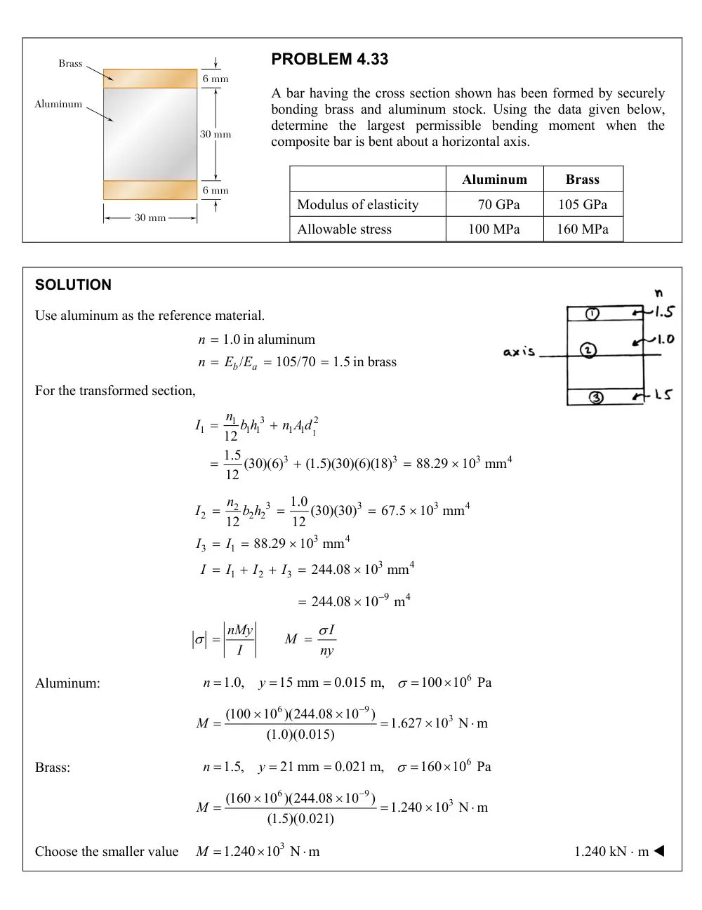
30 mm
6 mm
6 mm
30 mm
Aluminum
Brass
PROBLEM 4.33
A bar having the cross section shown has been formed by securely
bonding brass and aluminum stock. Using the data given below,
determine the largest permissible bending moment when the
composite bar is bent about a horizontal axis.
Aluminum
Brass
Modulus of elasticity
70 GPa
105 GPa
Allowable stress
100 MPa
160 MPa
SOLUTION
Use aluminum as the reference material.
1.0 in aluminum
/
105/70
1.5 in brass
b
a
n
n
E E
For the transformed section,
1
3
2
1
1
1 1
1 1
3
3
3
4
12
1.5 (30)(6)
(1.5)(30)(6)(18)
88.29
10 mm
12
n
I
b h
n A d
3
3
3
4
2
2
2 2
3
4
3
1
3
4
1
2
3
1.0 (30)(30)
67.5
10 mm
12
12
88.29
10 mm
244.08
10 mm
n
I
b h
I
I
I
I
I
I
9
4
244.08
10
m
nMy
I
M
I
ny
Aluminum:
6
1.0,
15 mm
0.015 m,
100 10 Pa
n
y
6
9
3
(100
10 )(244.08
10
)
1.627
10 N m
(1.0)(0.015)
M
Brass:
6
1.5,
21 mm
0.021 m,
160 10 Pa
n
y
6
9
3
(160
10 )(244.08
10
)
1.240
10 N m
(1.5)(0.021)
M
Choose the smaller value
3
1.240 10 N m
M
1.240 kN m
PROBLEM 4.40
A copper strip (Ec = 105 GPa) and an aluminum strip (Ea = 75 GPa)
are bonded together to form the composite beam shown. Knowing
that the beam is bent about a horizontal axis by a couple of moment
M = 35 N m, determine the maximum stress in (a) the aluminum
strip, (b) the copper strip.
SOLUTION
Use aluminum as the reference material.
1.0 in aluminum
/
105/75
1.4 in copper
c
a
n
n
E E
Transformed section:
A, mm2
nA, mm2
Ay0, mm
nAy0, mm3
216
216
7.5
1620
72
100.8
1.5
151.8
Σ
316.8
1771.2
0
1771.2
5.5909 mm
316.8
Y
The neutral axis lies 5.5909 mm above the bottom.
3
2
3
2
4
1
1
1 1
1
1 1
3
2
3
2
4
2
2
2 2
2
2
2
4
9
4
1
2
1.0 (24)(9)
(1.0)(24)(9)(1.9091)
2245.2 mm
12
12
1.4 (24)(3)
(1.4)(24)(3)(4.0909)
1762.5 mm
12
12
4839 mm
4.008 10
m
n
I
b h
n A d
n
I
b h
n A d
I
I
I
(a)
Aluminum:
6
9
1.0,
12
5.5909
6.4091mm
0.0064091
(1.0)(35)(0.0064091)
56.0
10
Pa
4.008
10
n
y
nMy
I
56.0 MPa
56.0 MPa
(b)
Copper:
6
9
1.4,
5.5909 mm
0.0055909 m
(1.4)(35)( 0.0055909)
68.4
10 Pa
4.008
10
n
y
nMy
I
68.4 MPa
68.4 MPa
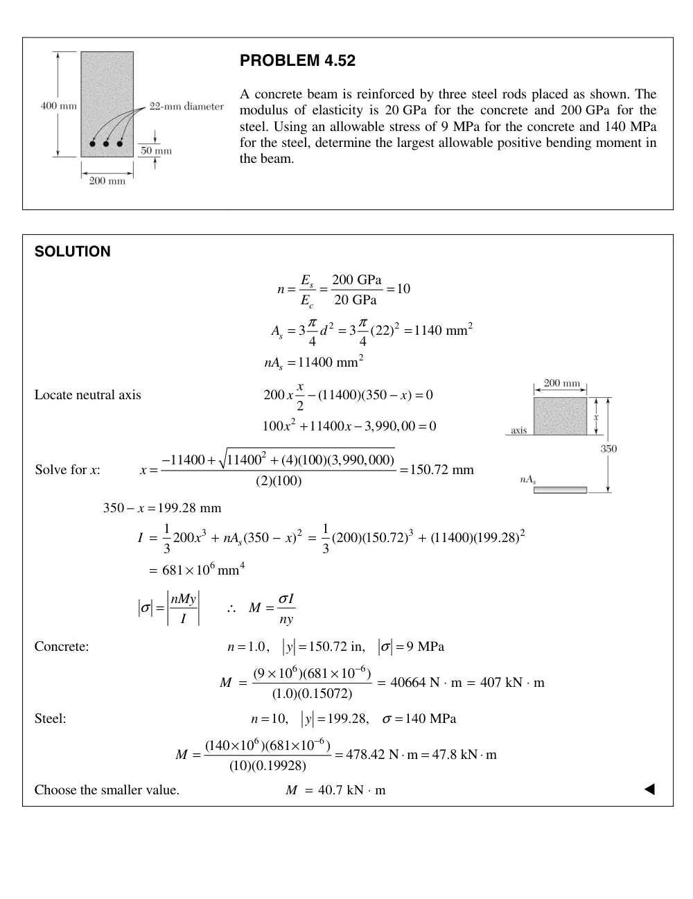
PROBLEM 4.52
A concrete beam is reinforced by three steel rods placed as shown. The
modulus of elasticity is 20 GPa for the concrete and 200 GPa for the
steel. Using an allowable stress of 9 MPa for the concrete and 140 MPa
for the steel, determine the largest allowable positive bending moment in
the beam.
SOLUTION
2
2
2
2
200 GPa
10
20 GPa
3
3
(22)
1140 mm
4
4
11400 mm
s
c
s
s
E
n
E
A
d
nA
π
π
=
=
=
=
=
=
=
Locate neutral axis
2
200
(11400)(350
)
0
2
100
11400
3,990,00
0
x x
x
x
x
−
−
=
+
−
=
Solve for x:
2
11400
11400
(4)(100)(3,990,000)
150.72 mm
(2)(100)
x
−
+
+
=
=
350
199.28 mm
− x
=
3
2
3
2
6
4
1
1
200
(350
)
(200)(150.72)
(11400)(199.28)
3
3
681
10 mm
s
I
x
nA
x
=
+
−
=
+
=
×
nMy
I
M
I
ny
σ
σ =
∴
=
Concrete:
1.0,
150.72 in,
9 MPa
n
y
σ
=
=
=
6
6
(9
10 )(681
10
)
40664 N m
407 kN m
(1.0)(0.15072)
M
−
×
×
=
=
⋅
=
⋅
Steel:
10,
199.28,
140 MPa
n
y
σ
=
=
=
6
(140 10 )(681 10 6
)
478.42 N m
47.8 kN m
(10)(0.19928)
M
−
×
×
=
=
⋅
=
⋅
Choose the smaller value.
40.7 kN
m
M =
⋅
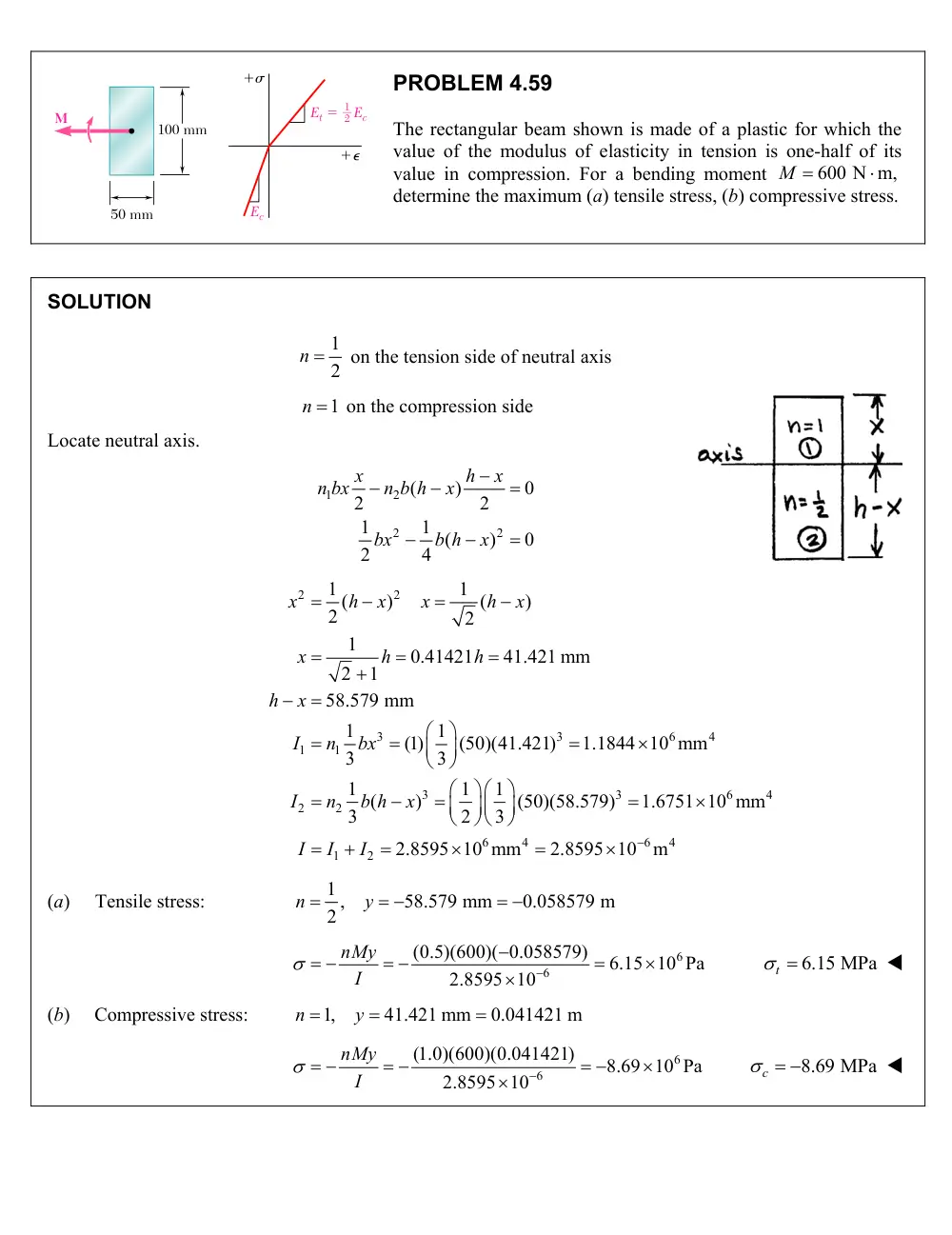
50 mm
100 mm
�
�
�
�
Et �
Ec
1
2
Ec
M
PROBLEM 4.59
The rectangular beam shown is made of a plastic for which the
value of the modulus of elasticity in tension is one-half of its
value in compression. For a bending moment
M 600 N m,
determine the maximum (a) tensile stress, (b) compressive stress.
SOLUTION
1
n 2
on the tension side of neutral axis
n 1
on the compression side
Locate neutral axis.
1
2
2
2
(
)
0
2
2
1
1 (
)
0
2
4
x
h
x
n bx
n b h
x
bx
b h
x
2
2
3
3
6
4
1
1
3
3
6
4
2
2
6
4
6
1
2
1
1
(
)
(
)
2
2
1
0.41421
41.421 mm
2
1
58.579 mm
1
(1) 1
(50)(41.421)
1.1844 10 mm
3
3
1
1
1
(
)
(50)(58.579)
1.6751 10 mm
3
2
3
2.8595 10 mm
2.8595 10
m
x
h
x
x
h
x
x
h
h
h
x
I
n
bx
I
n
b h
x
I
I
I
4
(a)
Tensile stress:
1 ,
58.579 mm
0.058579 m
2
n
y
6
6
(0.5)(600)( 0.058579)
6.15 10 Pa
2.8595 10
nMy
I
6.15 MPa
t
(b)
Compressive stress:
1,
41.421 mm
0.041421 m
n
y
6
6
(1.0)(600)(0.041421)
8.69 10 Pa
2.8595 10
nMy
I
8.69 MPa
c
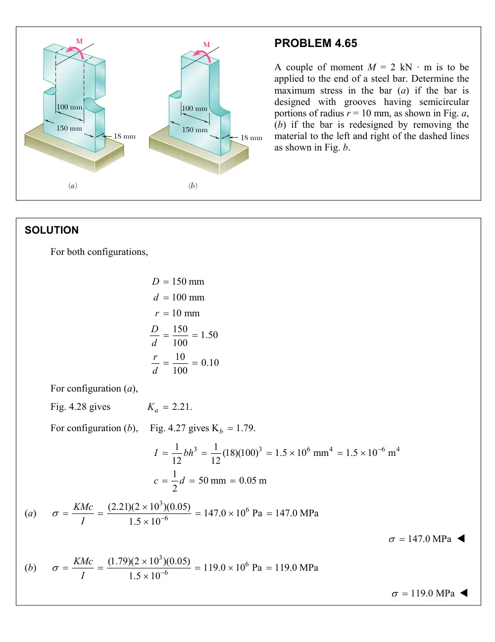
(a)
(b)
100 mm
150 mm
18 mm
100 mm
150 mm
18 mm
M
M
PROBLEM 4.65
A couple of moment M = 2 kN · m is to be
applied to the end of a steel bar. Determine the
maximum stress in the bar (a) if the bar is
designed with grooves having semicircular
portions of radius r = 10 mm, as shown in Fig. a,
(b) if the bar is redesigned by removing the
material to the left and right of the dashed lines
as shown in Fig. b.
SOLUTION
For both configurations,
150 mm
100 mm
10 mm
150
1.50
100
10
0.10
100
D
d
r
D
d
r
d
For configuration (a),
Fig. 4.28 gives
Ka 2.21.
For configuration (b),
Fig. 4.27 gives K
b 1.79.
3
3
6
4
6
4
1
1 (18)(100)
1.5
10 mm
1.5
10
m
12
12
1
50 mm
0.05 m
2
I
bh
c
d
(a)
3
6
6
(2.21)(2
10 )(0.05)
147.0
10 Pa
147.0 MPa
1.5
10
KMc
I
147.0 MPa
(b)
3
6
6
(1.79)(2
10 )(0.05)
119.0
10 Pa
119.0 MPa
1.5
10
KMc
I
119.0 MPa