
MEE 320 Problems Chapter 5, Spring 2018
Lebanese American University · Strength of Material · 12 pages · Dr. Carine Habchi

Showing the first 10 of 12 pages. Download the PDF to see all of it.
More MEE 320 files
Show the text of this chapter
SOLUTION
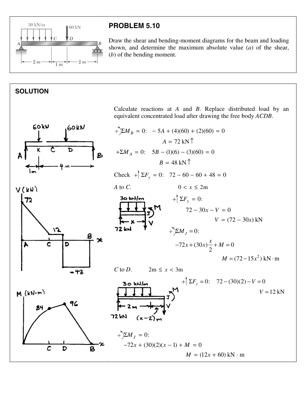
PROBLEM 5.10
Draw the shear and bending-moment diagrams for the
shown, and determine the maximum absolute value
(b) of the bending moment.
Calculate reactions at A and B. Replace distrib
equivalent concentrated load after drawing the free b
0:
5
(4)(60)
(2)(60)
0
72 kN
MB
A
A
Σ
=
−
+
+
=
=
↑
0:
5
(1)(6)
(3)(60)
0
48 kN
M A
B
B
+Σ
=
−
−
=
=
↑
Check
0:
72
60
60
48
0
ΣFy
=
−
−
+
=
A to C.
0
2m
< x
≤
0:
72
30
0
(72
y
F
x
V
V
Σ
=
−
−
=
=
−
0:
72
(30 )
0
2
(72
J
M
x
x
x
M
M
Σ
=
−
+
+
=
=
C to D.
2m
3m
≤ x
<
0:
72
(30)(2
ΣFy
=
−
0:
72
(30)(2)(
1)
0
(12
60) kN m
J
M
x
x
M
M
x
Σ
=
−
+
−
+
=
=
+
⋅
e beam and loading
e (a) of the shear,
buted load by an
body ACDB.
30 ) kN
x
2
2
15
x ) kN m
−
⋅
2)
0
12 kN
V
V
−
=
=
m
PR
0:
Fy
V
Σ
=
+
0:
MJ
M
M
Σ
=
−
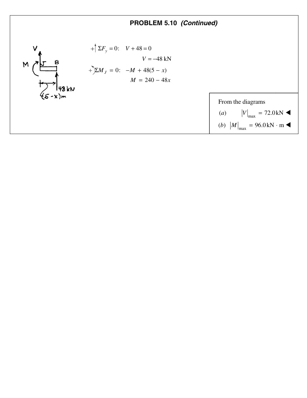
ROBLEM 5.10 (Continued)
48
0
48 kN
V
=
= −
48(5
)
240
48
x
M
x
+
−
=
−
From the diagrams
(a)
max
72.0
V
=
(b)
max
96.0kN
M
=
kN
⋅ m
H
A
7 @ 200 mm � 1400 mm
Hinge
30 mm
20 mm
C
B
D
E
F
G
300 N
300 N
300 N
40 N
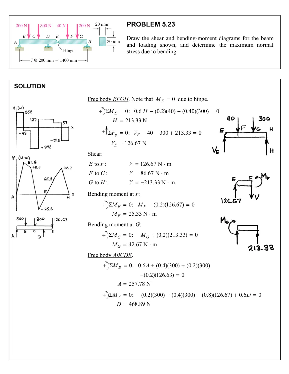
PROBLEM 5.23
Draw the shear and bending-moment diagrams for the beam
and loading shown, and determine the maximum normal
stress due to bending.
SOLUTION
Free body EFGH. Note that
0
ME
due to hinge.
0: 0.6
(0.2)(40)
(0.40)(300)
0
213.33 N
ME
H
H
0:
40
300
213.33
0
126.67 N
y
E
E
F
V
V
Shear:
to :
126.67 N m
to
:
86.67 N m
to
:
213.33 N m
E
F
V
F
G
V
G
H
V
Bending moment at F:
0:
(0.2)(126.67)
0
25.33 N m
F
F
F
M
M
M
Bending moment at G:
0:
(0.2)(213.33)
0
42.67 N m
G
G
G
M
M
M
Free body ABCDE.
0: 0.6
(0.4)(300)
(0.2)(300)
(0.2)(126.63)
0
257.78 N
MB
A
A
0:
(0.2)(300)
(0.4)(300)
(0.8)(126.67)
0.6
0
468.89 N
M A
D
D
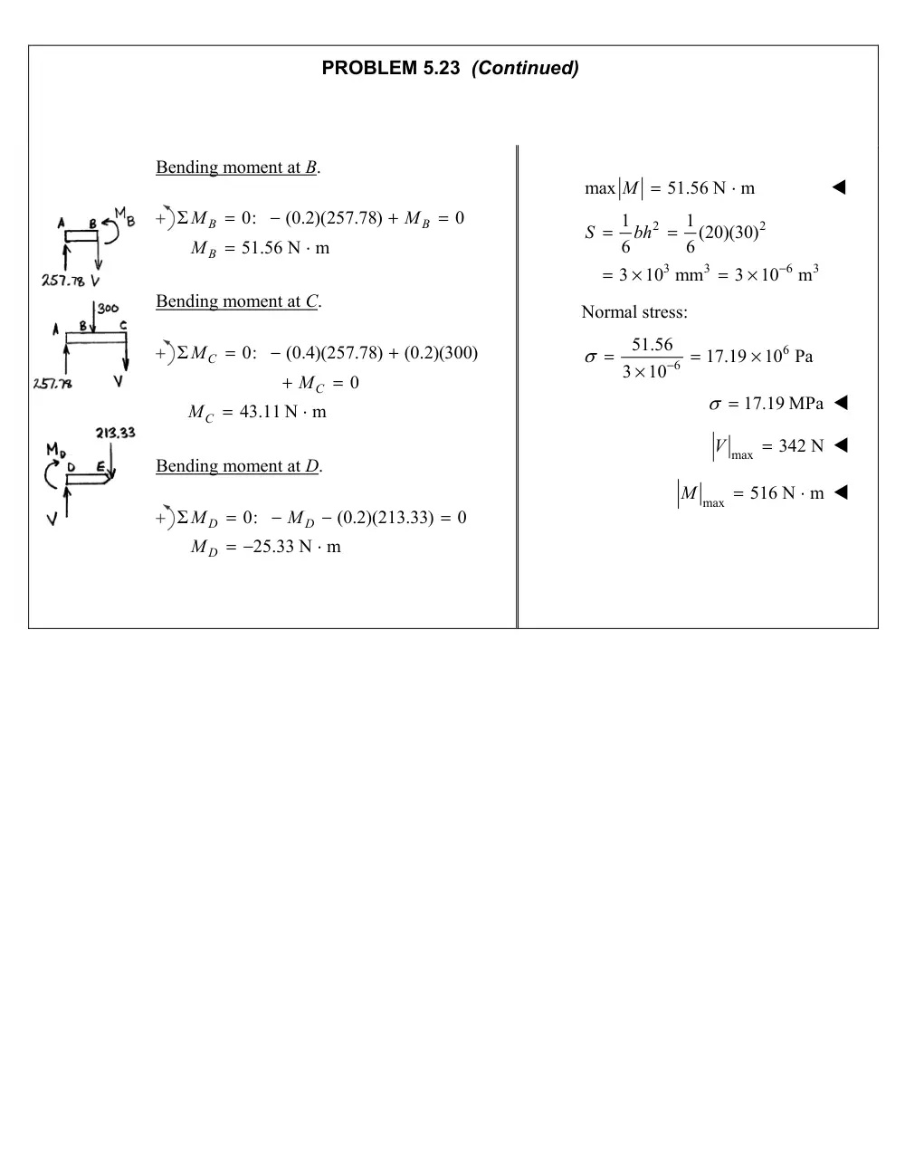
PROBLEM 5.23 (Continued)
Bending moment at B.
0:
(0.2)(257.78)
0
51.56 N m
B
B
B
M
M
M
Bending moment at C.
0:
(0.4)(257.78)
(0.2)(300)
0
43.11 N m
C
C
C
M
M
M
Bending moment at D.
0:
(0.2)(213.33)
0
25.33 N m
D
D
D
M
M
M
max
51.56 N m
M
2
2
3
3
6
3
1
1 (20)(30)
6
6
3
10 mm
3
10
m
S
bh
Normal stress:
6
6
51.56
17.19
10 Pa
3
10
17.19 MPa
max
342 N
V
max
516 N m
M
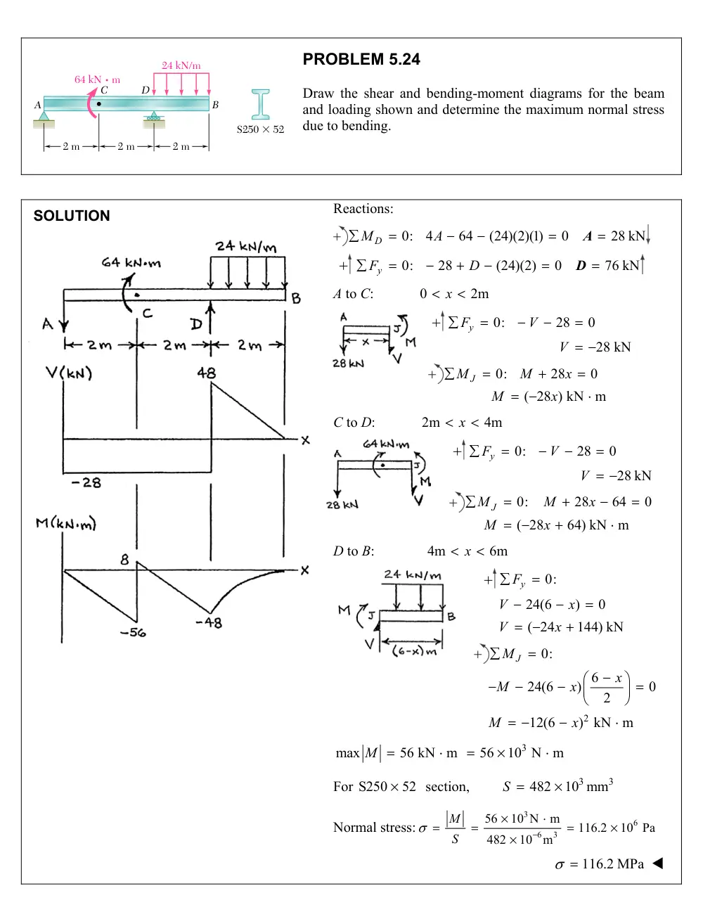
24 kN/m
64 kN ? m
B
A
C
D
2 m
2 m
2 m
S250 � 52
PROBLEM 5.24
Draw the shear and bending-moment diagrams for the beam
and loading shown and determine the maximum normal stress
due to bending.
SOLUTION
Reactions:
0:
4
64
(24)(2)(1)
0
28 kN
MD
A
A
0:
28
(24)(2)
0
76 kN
Fy
D
D
A to C:
0
2m
x
0:
28
0
28 kN
Fy
V
V
0:
28
0
( 28 ) kN m
MJ
M
x
M
x
C to D:
2m
4m
x
0:
28
0
28 kN
Fy
V
V
0:
28
64
0
( 28
64) kN m
MJ
M
x
M
x
D to B:
4m
6m
x
0:
24(6
)
0
( 24
144) kN
y
F
V
x
V
x
2
0:
6
24(6
)
0
2
12(6
) kN m
J
M
x
M
x
M
x
3
max
56 kN m
56
10 N m
M
For S250
52
section,
3
3
482
10 mm
S
Normal stress:
3
6
6
3
56
10 N
m
116.2
10 Pa
482
10
m
M
S
116.2 MPa
B
A
a
C
D
P
Q
12 mm
18 mm
500 mm
500 mm
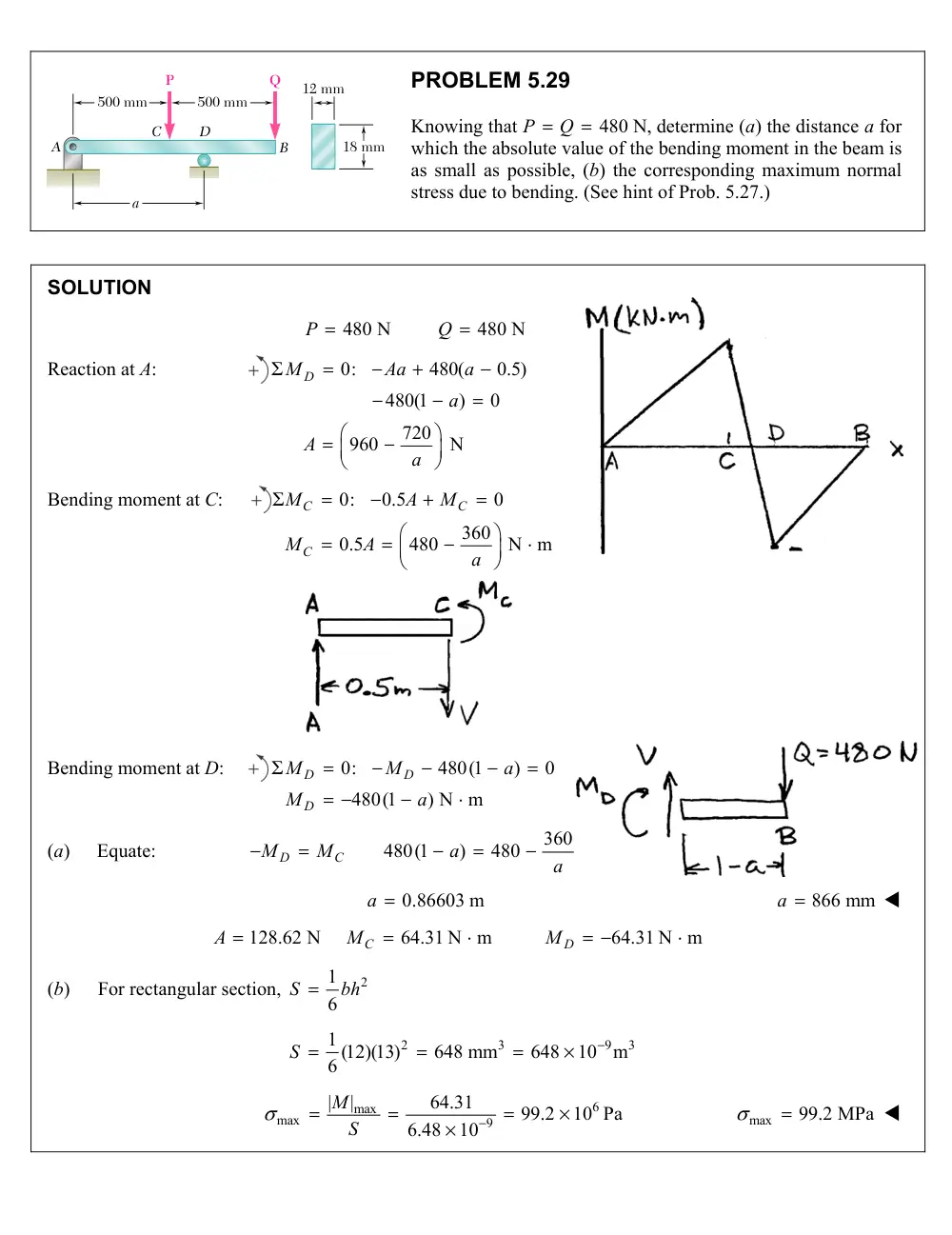
PROBLEM 5.29
Knowing that
480 N,
P
Q
determine (a) the distance a for
which the absolute value of the bending moment in the beam is
as small as possible, (b) the corresponding maximum normal
stress due to bending. (See hint of Prob. 5.27.)
SOLUTION
480 N
480 N
P
Q
Reaction at A:
0:
480(
0.5)
480(1
)
0
720
960
N
MD
Aa
a
a
A
a
Bending moment at C:
0:
0.5
0
360
0.5
480
N m
C
C
C
M
A
M
M
A
a
Bending moment at D:
0:
480(1
)
0
480(1
) N m
D
D
D
M
M
a
M
a
(a)
Equate:
360
480(1
)
480
D
C
M
M
a
a
a 0.86603 m
a 866 mm
128.62 N
64.31 N m
64.31 N m
C
D
A
M
M
(b)
For rectangular section,
2
1
6
S
bh
2
3
9
3
1 (12)(13)
648 mm
648
10
m
6
S
6
max
max
9
|
|
64.31
99.2
10 Pa
6.48
10
M
S
max
99.2 MPa
300 N
300 N
200 mm
75 mm
200 mm
200 mm
A
C
D
B
F
E
PROBLEM 5.45
Draw the shear and bending-moment diagrams for the beam and
loading shown, and determine the maximum absolute value (a) of
the shear, (b) of the bending moment.
SOLUTION
3
0:
0.075
(0.2)(300)
(0.6)(300)
0
3.2
10 N
A
EF
EF
M
F
F
3
0:
0
3.2
10 N
x
x
EF
x
F
A
F
A
0:
300
300
0
600 N
y
y
y
F
A
A
Couple at D:
3
(0.075)(3.2
10 )
240 N m
MD
Shear:
A to C:
V 600 N
C to B:
600
300
300 N
V
Areas under shear diagram:
A to C:
(0.2)(600)
120 N m
V dx
C to D:
(0.2)(300)
60 N m
V dx
D to B:
(0.2)(300)
60 N m
V dx
Bending moments:
0
M A
0
120
120 N m
120
60
180 N m
180
240
60 N m
60
60
0
C
D
D
B
M
M
M
M
Maximum
V 600 N
Maximum
180.0 N m
M
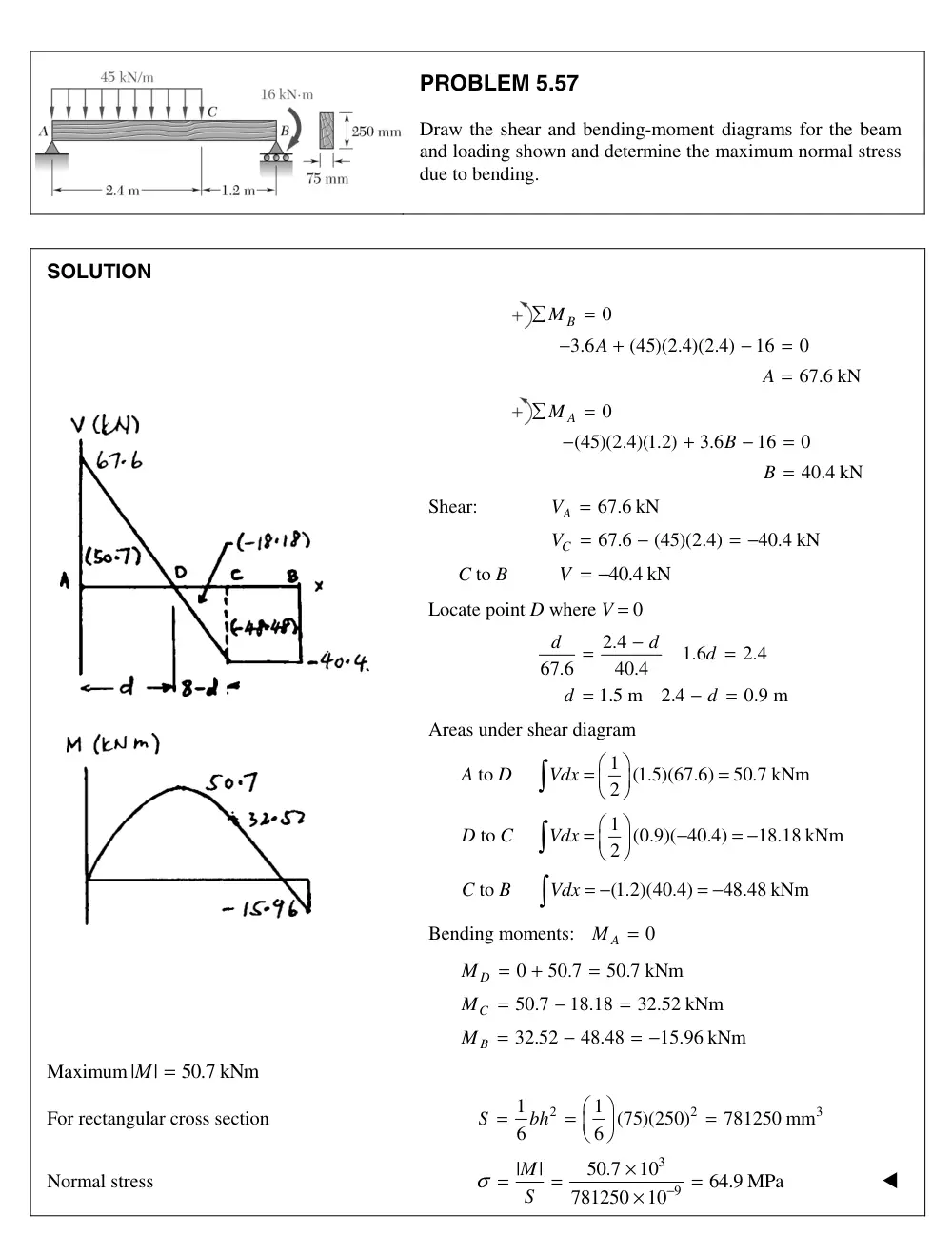
PROBLEM 5.5
Draw the shear and bending-moment diagrams for the beam
and loading shown and determine the maximum normal stress
due to bending.
SOLUTION
0
3.6
(45)(2.4)(2.4)
16
0
67.6 kN
B
M
A
A
=
−
+
−
=
=
0
(45)(2.4)(1.2)
3.6
16
0
40.4 kN
A
M
B
B
=
−
+
−
=
=
Shear:
67.6 kN
VA
=
67.6
(45)(2.4)
40.4 kN
VC
=
−
= −
C to B
V = −40.4 kN
Locate point D where V = 0
2.4
1.6
2.4
67.6
40.4
1.5 m
2.4
0.9 m
d
d
d
d
d
−
=
=
=
−
=
Areas under shear diagram
A to D
1 (1.5)(67.6)
50.7 kNm
2
Vdx
=
=
D to C
1 (0.9)( 40.4)
18.18 kNm
2
Vdx
=
−
= −
C to B
(1.2)(40.4)
48.48 kNm
Vdx = −
= −
Bending moments:
0
MA
=
0
50.7
50.7 kNm
MD
=
+
=
50.7
18.18
32.52 kNm
MC
=
−
=
32.52
48.48
15.96 kNm
MB
=
−
= −
Maximum |
|
M = 50.7 kNm
For rectangular cross section
2
2
3
1
1 (75)(250)
781250 mm
6
6
S
bh
=
=
=
Normal stress
3
9
|
|
50.7
10
64.9 MPa
781250
10
M
S
σ
−
×
=
=
=
×
7
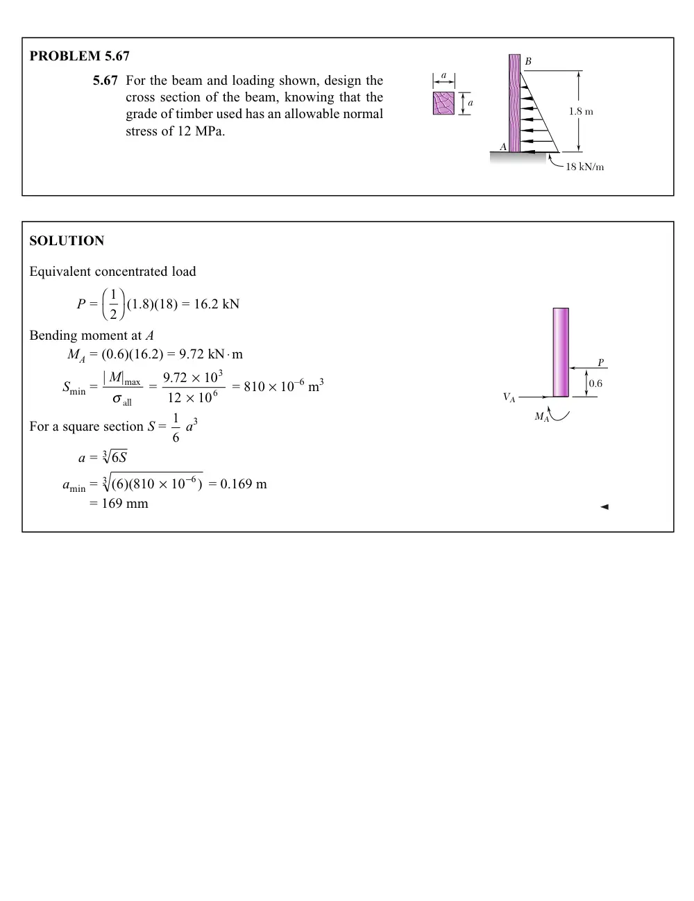
PROBLEM 5. 7
B
A
a
a
18 kN/m
1.8 m
5.67 For the beam and loading shown, design the
cross section of the beam, knowing that the
grade of timber used has an allowable normal
stress of 12 MPa.
SOLUTION
Equivalent concentrated load
P = 1
2�� �� (1.8)(18) = 16.2 kN
Bending moment at A
MA = (0.6)(16.2) = 9.72 kN◊m
Smin = |
M|max
s all
= 9 72
10
12
10
3
6
.
¥
¥
= 810 ¥ 10–6 m3
0.6
P
MA
VA
For a square section S = 1
6 a3
a = 6
3
S
amin = ( )(810
)
6
10 6
3
¥
-
= 0.169 m
= 169 mm
6
100 kN/m
80 kN
A
C
B
0.8 m
1.6 m
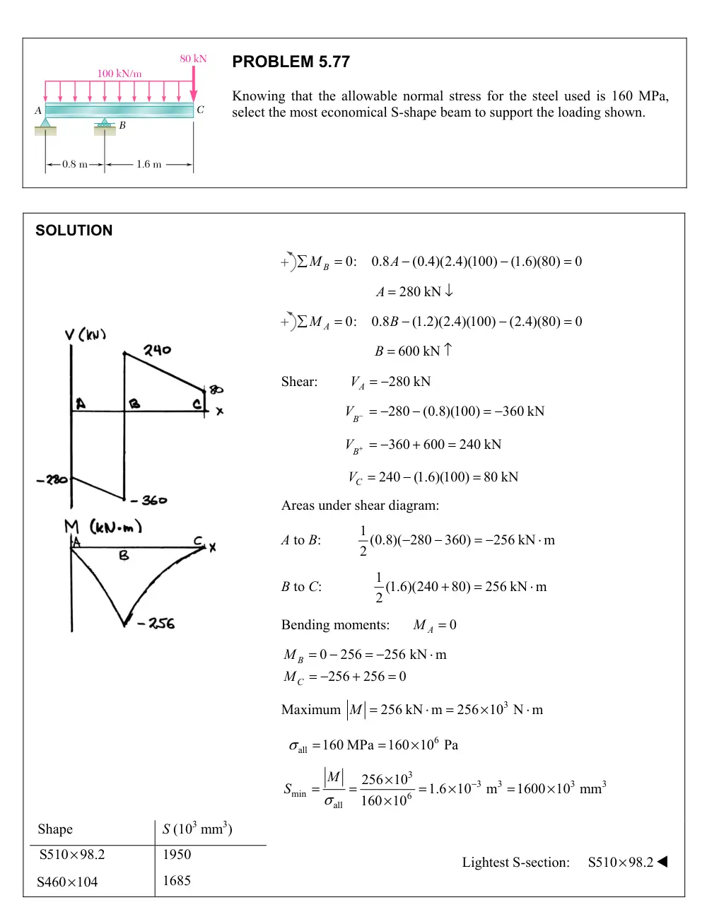
PROBLEM 5.77
Knowing that the allowable normal stress for the steel used is 160 MPa,
select the most economical S-shape beam to support the loading shown.
SOLUTION
0:
0.8
(0.4)(2.4)(100)
(1.6)(80)
0
MB
A
280 kN
A
0:
0.8
(1.2)(2.4)(100)
(2.4)(80)
0
M A
B
B 600 kN
Shear:
280 kN
A
V
280
(0.8)(100)
360 kN
B
V
360
600
240 kN
B
V
240
(1.6)(100)
80 kN
C
V
Areas under shear diagram:
A to B:
1 (0.8)( 280
360)
256 kN m
2
B to C:
1 (1.6)(240
80)
256 kN m
2
Bending moments:
0
M A
0
256
256 kN m
256
256
0
B
C
M
M
Maximum
3
256 kN m
256 10 N m
M
6
all
160 MPa
160 10 Pa
3
3
3
3
3
min
6
all
256 10
1.6 10
m
1600 10 mm
160 10
M
S
Shape
S (103 mm3)
S510
98.2
1950
S460 104
1685
Lightest S-section:
S510
98.2
P
P
B
C
D
a
2.4 m 2.4 m 2.4 m
12.5 mm
12.5 mm
150 mm
200 mm
A
a
PROBLEM 5.90
Beams AB, BC, and CD have the cross section shown
and are pin-connected at B and C. Knowing that the
allowable normal stress is 110 MPa in tension and
150 MPa in compression, determine (a) the largest
permissible value of P if beam BC is not to be
overstressed, (b) the corresponding maximum
distance a for which the cantilever beams AB and CD
are not overstressed.
SOLUTION
0
B
C
B
C
M
M
V
V
P
Area B to E of shear diagram: 2.4P
0
2.4
2.4
E
F
M
P
P
M
Centroid and moment of inertia:
Part
2
A(mm )
y (mm)
3
Ay (mm )
d (mm)
2
4
Ad (mm )
4
I (mm )
2500
156.25
390,625
34.82
6
3.031
10
6
0.0326
10
1875
75
140,625
46.43
6
4.042
10
6
3.516
10
4375
531,250
6
7.073
10
6
3.548
10
2
6
4
531,250
121.43 mm
4375
10.621 10 mm
Y
I
Ad
I
Location
y(mm)
3
3
/ (10 mm )
I y
also
6
3
(10
m )
Top
41.07
258.6
Bottom
121.43
87.47
PROBLEM 5.90 (Continued)
Bending moment limits:
/
M
I y
Tension at E and F:
6
6
3
(110 10 )( 87.47 10
)
9.622 10 N m
Compression at E and F:
6
6
3
( 150 10 )(258.6 10
)
38.8 10 N m
Tension at A and D:
6
6
3
(110 10 )(258.6 10
)
28.45 10 N m
Compression at A and D:
6
6
3
( 150 10 )( 87.47 10
)
13.121 10 N m
(a)
Allowable load P:
3
3
2.4
9.622 10
4.01 10 N
P
P
P 4.01 kN
Shear at A:
VA
P
Area A to B of shear diagram:
aVA
aP
Bending moment at A:
3
4.01
10
M A
aP
a
(b)
Distance a:
3
3
4.01 10
13.121 10
a
a 3.27 m