
MEE 320 Problems Chapter 7, Spring 2018
Lebanese American University · Strength of Material · 15 pages · Dr. Carine Habchi

Showing the first 10 of 15 pages. Download the PDF to see all of it.
More MEE 320 files
Show the text of this chapter
SO
OLUTION
F
F
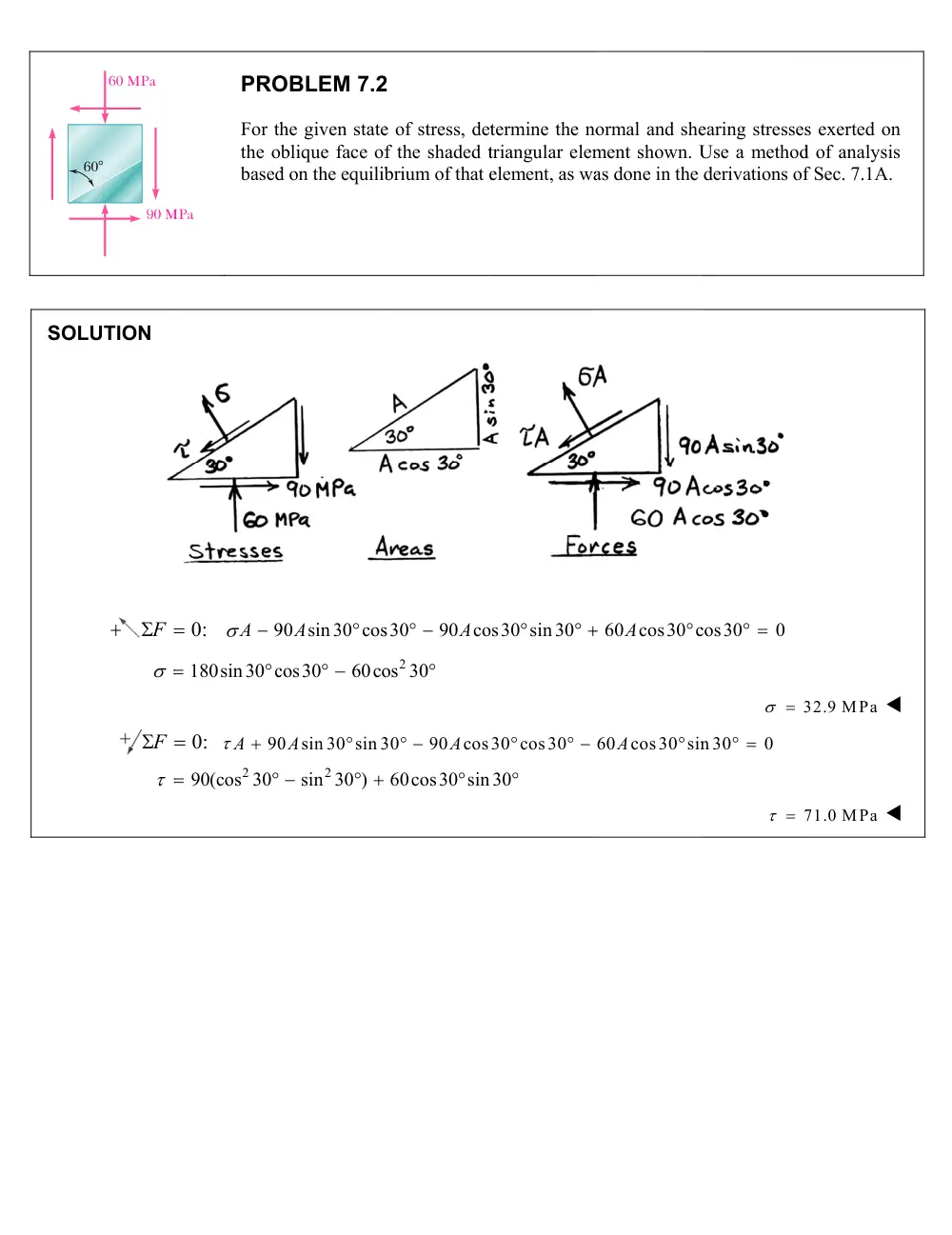
60 MPa
90 M
608
PRO
For th
the o
based
0:
A 9
180sin30 c
0:
90
A
2
90(cos 30
MPa
OBLEM 7.2
he given state
blique face of
d on the equilib
90 sin30 cos
A
cos30
60co
0
sin 30 sin 3
A
2
sin 30 )
2
e of stress, det
f the shaded t
brium of that e
s30
90 co
A
2
os 30
30
90
cos
A
60cos30 sin
termine the no
triangular elem
element, as wa
s30 sin30
30 cos30
30
ormal and she
ment shown. U
as done in the
60 cos30 c
A
60
cos30 sin
A
earing stresses
Use a method
derivations of
cos30
0
3
n 30
0
7
s exerted on
d of analysis
f Sec. 7.1A.
32.9 MPa
71.0 MPa
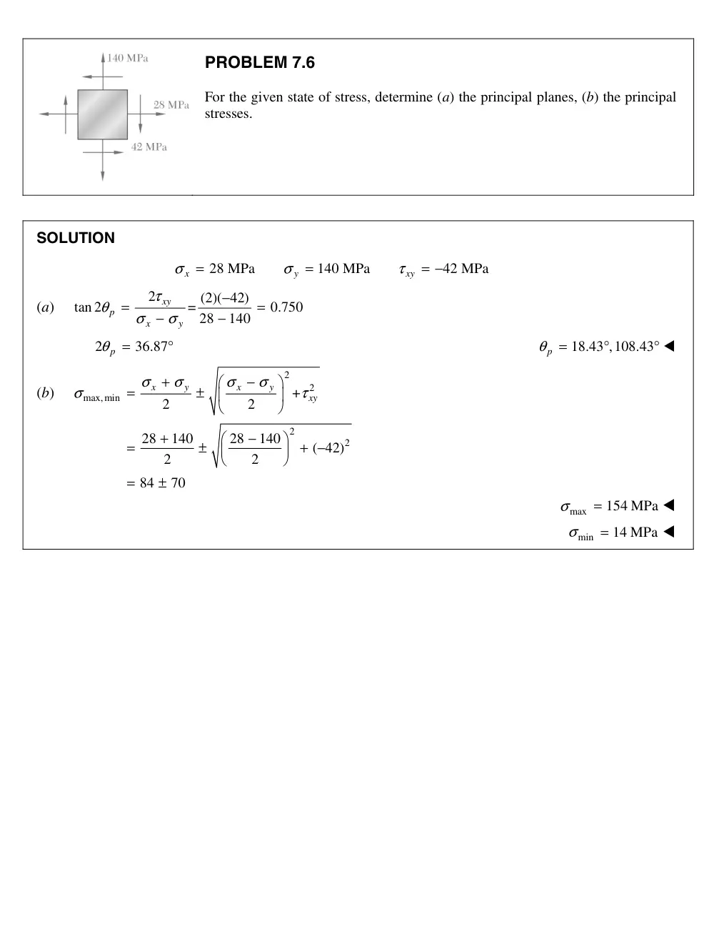
PROBLEM 7.6
For the given state of stress, determine (a) the principal planes, (b) the principal
stresses.
SOLUTION
28 MPa
140 MPa
42 MPa
x
y
xy
σ
σ
τ
=
=
= −
(a)
2
(2)( 42)
tan 2
=
0.750
28
140
xy
p
x
y
τ
θ
σ
σ
−
=
=
−
−
2
36.87
θp
=
°
18.43 ,108.43
θp
=
°
°
(b)
2
2
max,min
2
2
+
2
2
28
140
28
140
( 42)
2
2
84
70
x
y
x
y
xy
σ
σ
σ
σ
σ
τ
+
−
=
±
+
−
=
±
+ −
=
±
max
154 MPa
σ
=
min
14 MPa
σ
=
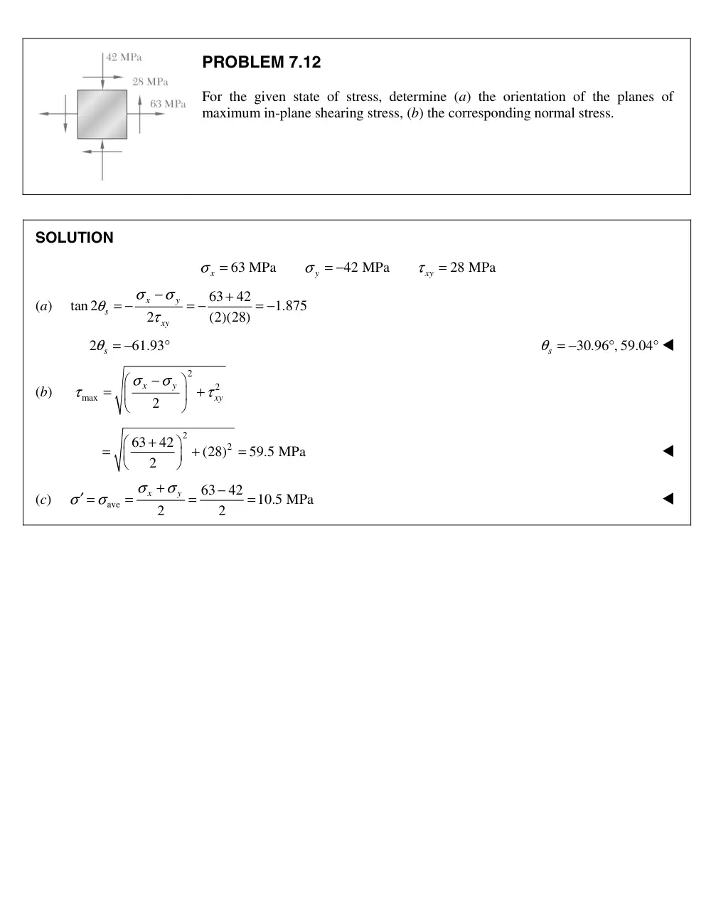
PROBLEM 7.1
For the given state of stress, determine (a) the orientation of the planes of
maximum in-plane shearing stress, (b) the corresponding normal stress.
SOLUTION
63 MPa
42 MPa
28 MPa
x
y
xy
σ
σ
τ
=
= −
=
(a)
63
42
tan 2
1.875
2
(2)(28)
x
y
s
xy
σ
σ
θ
τ
−
+
= −
= −
= −
2
61.93
s
θ = −
°
30.96 , 59.04
s
θ = −
°
°
(b)
2
2
max
2
x
y
xy
σ
σ
τ
τ
−
=
+
2
2
63
42
(28)
59.5 MPa
2
+
=
+
=
(c)
ave
63
42
10.5 MPa
2
2
x
y
σ
σ
σ
σ
+
−
′ =
=
=
=
2
SO
For
All
50 m
OLUTION
r plane a-a,
lowable value
P
mm
a
PR
Two
a-a
stres
cent
65 .
0
s
s
x
P
P
of P is the sm
a
25�
OBLEM 7.2
o members of
that forms an
sses for the glu
tric load P that
2
2
0,
0,
cos
(50
sin 65
(
)sin
sin 65 cos65
xy
x
y
x
y
A
A
maller one.
22
uniform cross
n angle of 25
ued joint are
t can be applie
2
3
2
3
sin
2
10
)(80 1
sin 6
cos
(
(50 10
)(
y
y
xy
xy
P
A
sin
s section 50
5 with the h
800 kPa
a
ed.
3
3
2
2
sin cos
0
)(800 10
65
(cos
sin
(8
0 10 3
)(60
n 65 cos65
80 mm are g
horizontal. Kn
and
600 k
2
3
3
0
sin 65
)
3.90 10
)
sin65
P
A
P
A
3
0 10 )
6.27
glued together
nowing that th
kPa, determin
5
0
N
cos65
0
3
7 10 N
P
r along plane
he allowable
ne the largest
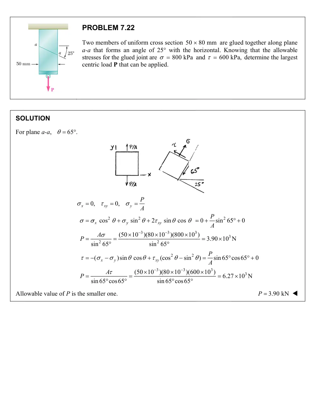
3.90 kN
PROBLEM 7.2
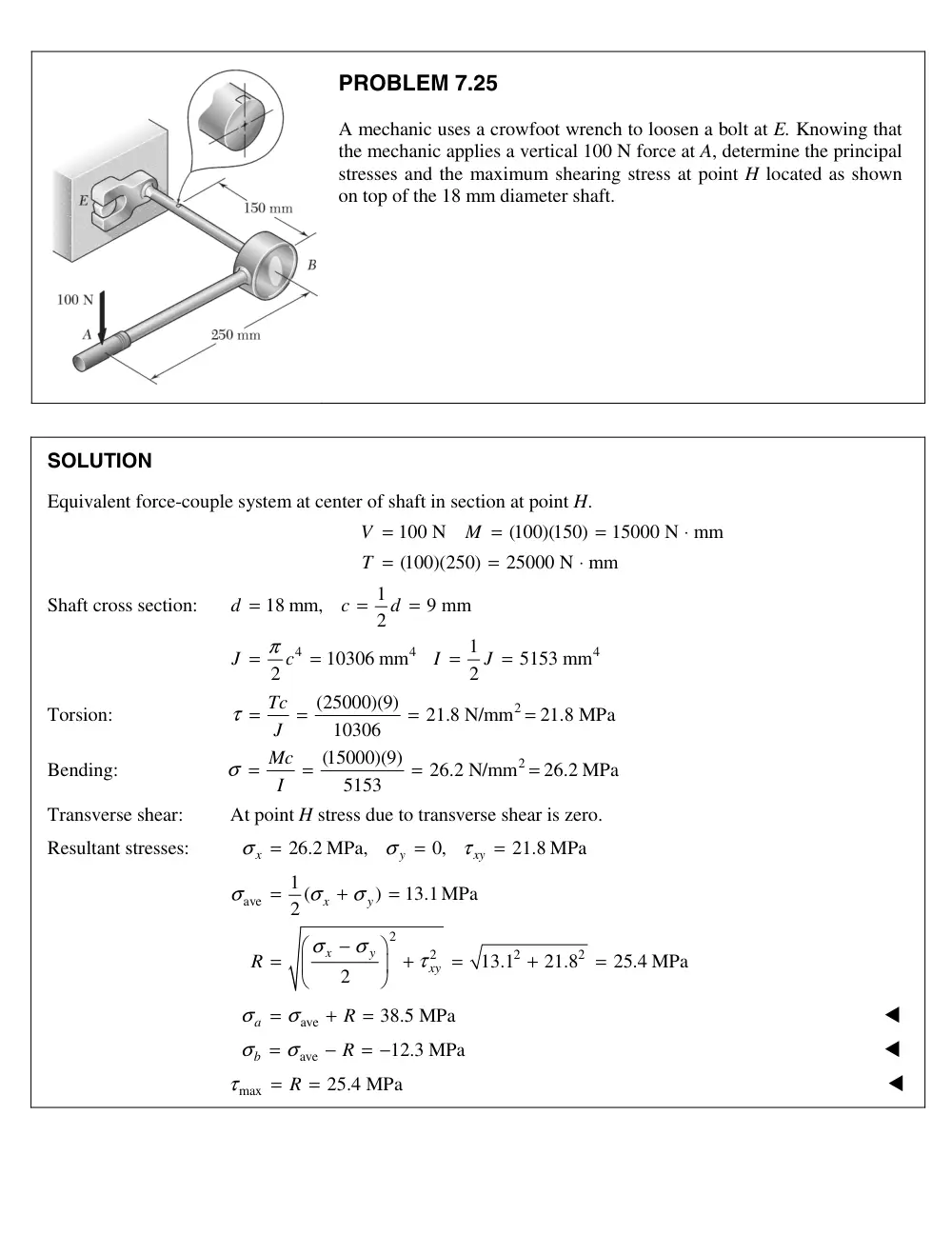
A mechanic uses a crowfoot wrench to loosen a bolt at E. Knowing that
the mechanic applies a vertical 100 N force at A, determine the principal
stresses and the maximum shearing stress at point H located as shown
on top of the 18 mm diameter shaft.
SOLUTION
Equivalent force-couple system at center of shaft in section at point H.
100 N
(100)(150)
15000 N mm
(100)(250)
25000 N mm
V
M
T
=
=
=
⋅
=
=
⋅
Shaft cross section:
4
4
4
1
18 mm,
9 mm
2
1
10306 mm
5153 mm
2
2
d
c
d
J
c
I
J
π
=
=
=
=
=
=
=
Torsion:
2
(25000)(9)
21.8 N/mm
21.8 MPa
10306
Tc
τ = J
=
=
=
Bending:
2
(15000)(9)
26.2 N/mm
26.2 MPa
5153
Mc
I
σ =
=
=
=
Transverse shear:
At point H stress due to transverse shear is zero.
Resultant stresses:
ave
2
2
2
2
26.2 MPa,
0,
21.8 MPa
1 (
)
13.1MPa
2
13.1
21.8
25.4 MPa
2
x
y
xy
x
y
x
y
xy
R
σ
σ
τ
σ
σ
σ
σ
σ
τ
=
=
=
=
+
=
−
=
+
=
+
=
ave
38.5 MPa
a
R
σ
= σ
+
=
ave
12.3 MPa
b
R
σ
= σ
−
= −
max
25.4 MPa
R
τ
=
=
5
SO
Forc
Tor
10 kN
LUTION
ce-couple syst
sion:
At po
200 mm
6 m
z
N
C
tem at center o
oint K, place l
mm
1
T
A
y
K
H
A
B
P
Th
th
de
at
4
1
2
2
4.1855
1
2
o
o
o
d
r
J
r
I
J
of tube in the p
10 kN
10 10
(10 1
2000 N
(10
1500
x
y
z
F
M
M
local x-axis in
51
(
24.37
24.37
y
o
xy
T
M
c
r
Tc
J
150 mm
51 mm
x
D
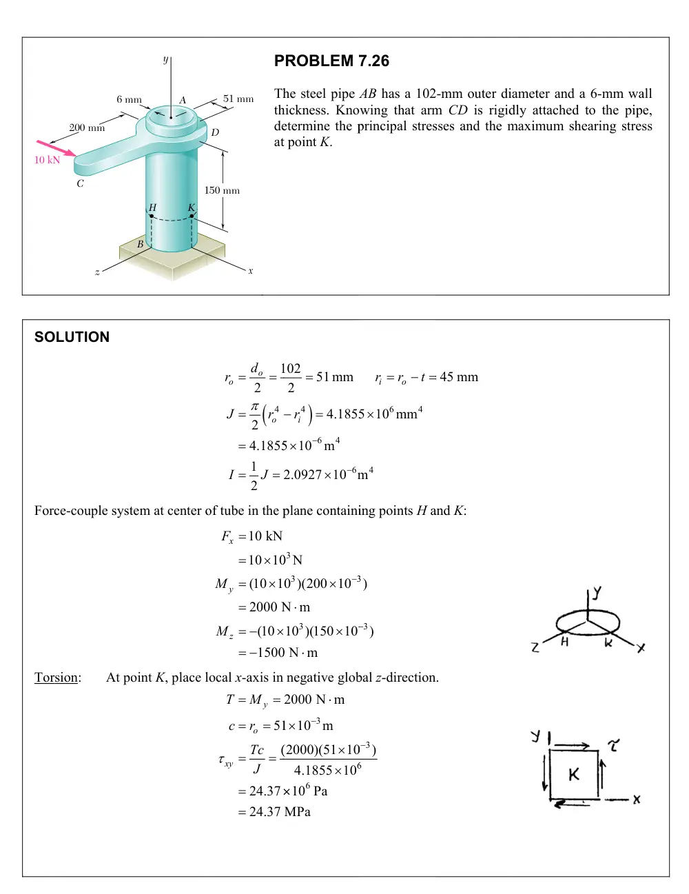
PROBLEM 7
he steel pipe A
hickness. Kno
etermine the p
t point K.
4
6
4
6
102
51 mm
2
4.1855
5 10
m
2.0927 10 m
ir
plane containi
3
3
3
3
0 N
0 )(200 10
N m
10 )(150 10
0 N m
negative glob
3
6
6
2000 N m
1 10
m
(2000)(51 10
4.1855 10
10 Pa
MPa
7.26
AB has a 102
wing that arm
principal stres
6
4
4
5 10 mm
m
i
o
r
r
t
ing points H a
3
3
)
)
bal z-direction
3
6
0
)
2-mm outer di
m CD is rigid
sses and the m
45 mm
and K:
n.
ameter and a
dly attached t
maximum she
6-mm wall
to the pipe,
aring stress
PROBLEM 7.26 (Continued)
Transverse shear:
Stress due to transverse shear
x
V
F
is zero at point K.
Bending:
3
6
6
|
|
(1500)(51 10
)
|
|
36.56 10 Pa
36.56 MPa
2.0927 10
z
y
M c
I
Point K lies on compression side of neutral axis.
36.56 MPa
y
Total stresses at point K:
ave
2
2
0,
36.56 MPa,
24.37 MPa
1 (
)
18.28 MPa
2
30.46 MPa
2
x
y
xy
x
y
x
y
xy
R
max
ave
18.28
30.46
R
max
12.18 MPa
min
ave
18.28
30.46
R
min
48.7 MPa
max
R
max
30.5 MPa
SO
Plo
(a)
OLUTION
otted points fo
25
90 MP
3
r Mohr’s circl
:
:
:
X
Y
C
tan 2
p
2
p
R
.
2
5
2
x
x y
y
Pa
30 MPa
60 MPa
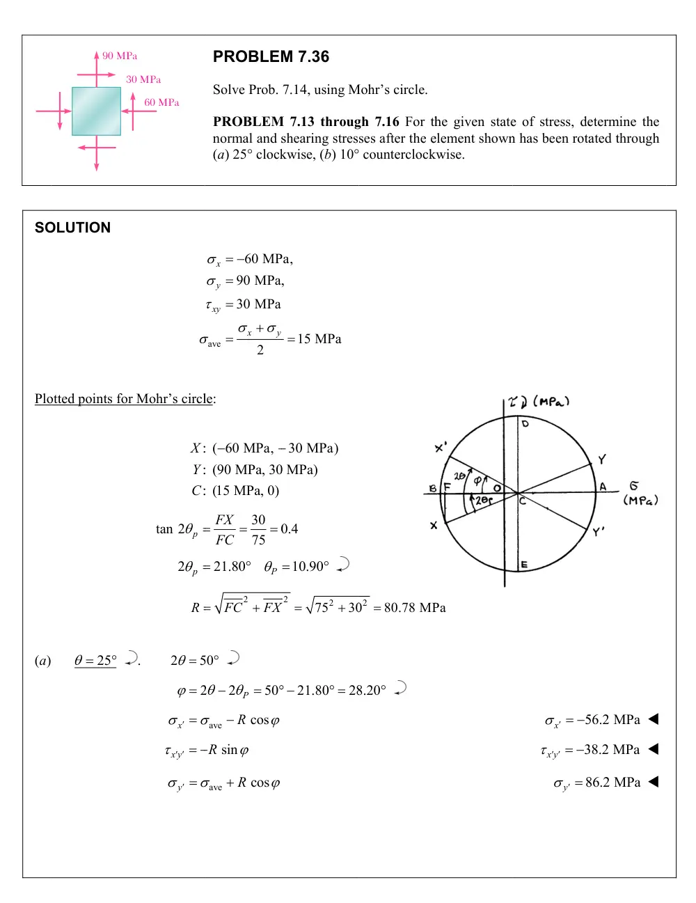
PROBLEM
Solve Prob.
PROBLEM
normal and s
(a) 25 clock
ave
60 MP
90 MPa,
30 MPa
2
x
y
xy
x
y
le:
: ( 60 MPa,
: (90 MPa, 30
: (15 MPa, 0)
30
0
75
FX
FC
21.80
P
FC2
FX
50
2
2
50
P
ave
cos
R
R sin
ave
cos
R
M 7.36
7.14, using M
M 7.13 throug
shearing stres
kwise, (b) 10
Pa,
,
15 MPa
30 MPa)
0 MPa)
0.4
10.90
2
752
30
X
21.80
28
Mohr’s circle.
gh 7.16 For th
ses after the e
counterclock
02
80.78 MP
8.20
he given state
element shown
kwise.
Pa
e of stress, de
n has been rota
5
x
3
x y
8
y
etermine the
ated through
56.2 MPa
38.2 MPa
86.2 MPa
(b)
10
.
2
20
2
x
x y
R
y
PROB
0
2
21.8
p
ave
cos
R
sin
R
ave
cos
R
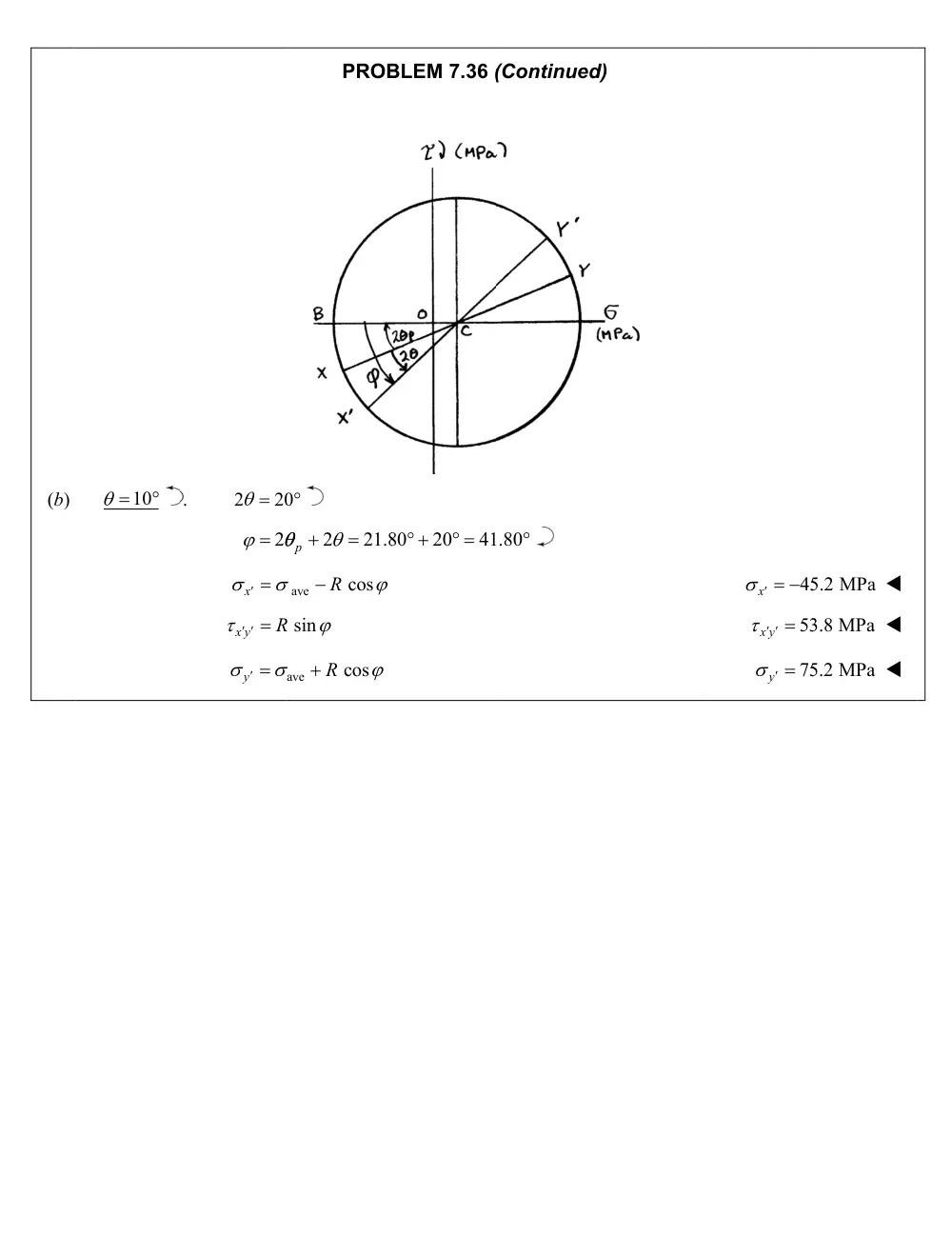
BLEM 7.36 (
80
20
41
(Continued)
.80
d)
45
x
53
x y
75
y
5.2 MPa
3.8 MPa
5.2 MPa
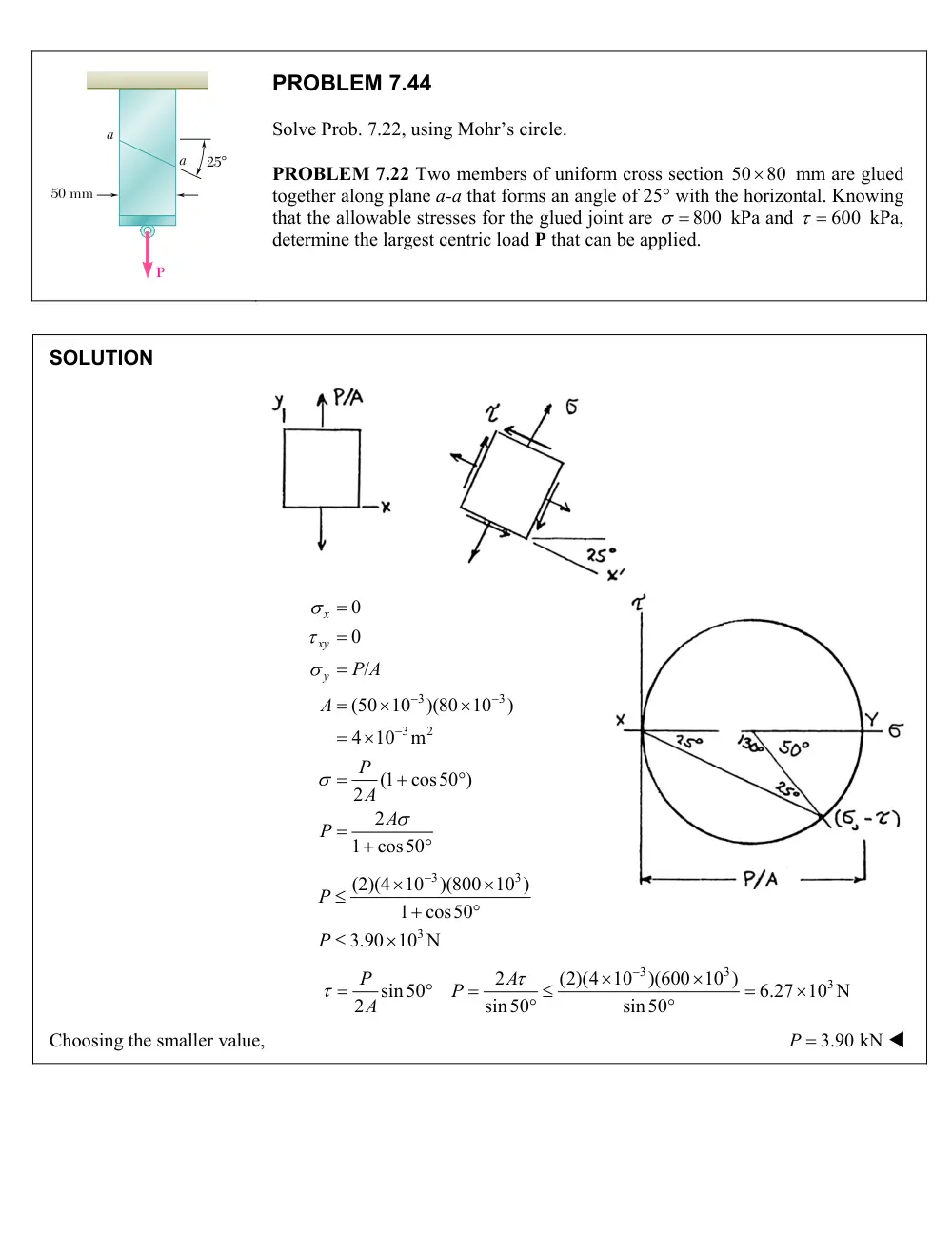
PROBLEM 7.44
Solve Prob. 7.22, using Mohr’s circle.
PROBLEM 7.22 Two members of uniform cross section 50
80
mm are glued
together along plane a-a that forms an angle of 25 with the horizontal. Knowing
that the allowable stresses for the glued joint are
800
kPa and
600
kPa,
determine the largest centric load P that can be applied.
SOLUTION
3
3
3
2
0
0
/
(50 10
)(80 10
)
4 10
m
(1
cos50 )
2
2
1
cos50
x
xy
y
P A
A
P
A
A
P
3
3
3
(2)(4 10
)(800 10 )
1
cos50
3.90 10 N
P
P
3
3
3
2
(2)(4 10
)(600 10 )
sin50
6.27 10 N
2
sin50
sin50
P
A
P
A
Choosing the smaller value,
P 3.90 kN
P
a
25�
50 mm
a
PROBLEM 7.55
Determine the principal planes and the principal
stresses for the state of plane stress resulting
from the superposition of the two states of
stress shown.
SOLUTION
Consider the state of stress on the left. We shall express it in terms of horizontal and vertical components.
Principal axes and principal stress:
ave
1 (118.3
56.7)
87.5
2
1 (118.3
56.7)
30.8
2
2
y
x
2
2
(30.8)
(75)
81.08
R
75
tan 2
2
67.67
30.8
p
p
33.8
p
, and
123.8
ave
max
87.5
81.08
R
max
168.6 MPa
in
ave
m
87.5
81.08
R
min
6.42 MPa
100 MPa
50 MPa
50 MPa
75 MPa
+
308
50cos30
43.30
43.30
50sin30
25.0
x
y
xy
PROBLEM 7.68
For the state of stress shown, determine the maximum shearing stress
when (a)
y 40
MPa, (b)
y 120
MPa. (Hint: Consider both in-plane
and out-of-plane shearing stresses.)
SOLUTION
(a)
ave
140 MPa,
40 MPa,
80 MPa
1 (
)
90 MPa
2
x
y
xy
x
y
2
2
2
2
50
80
94.34 MPa
2
x
y
xy
R
ave
ave
184.34 MPa
(max)
4.34 MPa
(min)
0
a
b
c
R
R
max(in-plane)
1 (
)
94.34 MPa
2
a
b
R
max
max
min
1
1
(
)
(
)
94.3 MPa
2
2
a
b
max
94.3 MPa
(b)
ave
140 MPa,
120 MPa,
80 MPa
1 (
)
130 MPa
2
x
y
xy
x
y
2
2
2
2
10
80
80.62 MPa
2
x
y
xy
R
ave
ave
210.62 MPa
(max)
49.38 MPa
0
(min)
a
b
c
R
R
max
min
210.62 MPa
0
a
c
max(in-plane)
86.62 MPa
R
max
max
min
1 (
)
105.3 MPa
2
max
105.3 MPa
80 MPa
y
z
x
140 MPa
σy
PROBLEM 7.71
For the state of stress shown, determine the maximum shearing stress
when (a) z 0, (b) z 60 MPa, (c) z 60 MPa.
SOLUTION
ave
1 (170
100)
135
2
1
1
(
)
(170
100)
35
2
2
x
y
2
2
(35)
(84)
91
R
135
91
226 MPa
A
135
91
44 MPa
B
(a)
0.
z
Point Z corresponding to the z axis is located at O, outside the circle drawn through A and B.
The largest of the 3 Mohr’s circles is the circle through O and A. We have
max
1
1
1
(
)
(226)
2
2
2
A
OA
max
113.0 MPa
(b)
60 MPa.
z
Point Z is located between B and A. The largest of the 3 circles is the one drawn
through A and B.
max
91.0 MPa
R
(c)
60 MPa.
z
Point Z is located outside the circle drawn through A and B. The largest of the 8
Mohr’s circles is the circle through Z and A. We have
max
1
1
(
)
(60
226)
2
2
ZA
max
143.0 MPa
z
x
84 MPa
y
170 MPa
100 MPa
z
PROBLEM 7.7
For the state of stress shown, determine the value of
τxy
for which the
maximum shearing stress is (a) 63 MPa, (b) 84 MPa.
SOLUTION
ave
105 MPa
42 MPa
1 (
)
73.5 MPa
2
31.5 MPa
2
x
y
x
y
x
y
U
σ
σ
σ
σ
σ
σ
σ
=
=
=
+
=
−
=
=
τ
(MPa)
(a)
For max
63 MPa
τ
=
Center of Mohr’s circle lies at point C.
Lines marked (a) show the limits on max.
τ
Limit on
σmax
is
max
2 max
126 MPa.
σ
= τ
=
For the Mohr’s circle
max
σa
= σ
corresponds to point Aa.
ave
2
2
2
2
2
2
126
73.5
52.5 MPa
52.5
31.5
42 MPa
a
xy
xy
R
R
U
R
U
σ
σ
τ
τ
=
−
=
−
=
=
+
= ±
−
= ±
−
= ±
(b)
For max
84 MPa
τ
=
Center of Mohr’s circle lies at point C.
R = 84 MPa
2
2
78.7 MPa
xy
R
U
τ
= ±
−
= ±
Checking
73.5
84
157.5 MPa
73.5
84
10.5 MPa
0
a
b
c
σ
σ
σ
=
+
=
=
−
= −
=
max
max
min
1 (
)
84 MPa
O.K.
2
τ
σ
σ
=
−
=
5
PROBLEM 7.79
For the state of stress shown, determine two values of
y
for which the
maximum shearing stress is 80 MPa.
SOLUTION
90 MPa,
0,
60 MPa
x
z
xz
Mohr’s circle of stresses in zx plane:
ave
2
2
2
2
1 (
)
45 MPa
2
45
60
75 MPa
2
x
z
x
y
zx
R
ave
ave
120 MPa,
30 MPa
a
b
R
R
Assume
max
120 MPa.
a
min
max
max
2
120
(2)(80)
y
40.0 MPa
y
Assume
min
30 MPa.
b
max
min
max
2
30
(2)(80)
y
130.0 MPa
y
z
y
x
σy
90 MPa
60 MPa