
EDUC 215 Chapter 9, Fall 2009
American University of Beirut · Learning and Human Development · 37 pages · Dr. Vivian Khamis
Showing the first 10 of 37 pages. Download the PDF to see all of it.
More EDUC 215 files
Show the text of this chapter
Chapter 22
Electromagnetic
Induction
Outline
1.
Induced Emf and Induced Current
2.
Motional Emf
3.
Magnetic Flux
4.
Faraday’s Law of Electromagnetic
Induction
5.
Lenz’s Law
6.
Application of Electromagnetic
Induction to the Reproduction of
Sound
7.
The Electric Generator
8.
Mutual Inductance and Self-
Inductance
9.
Transformers
1- Induced Emf and Induced Current
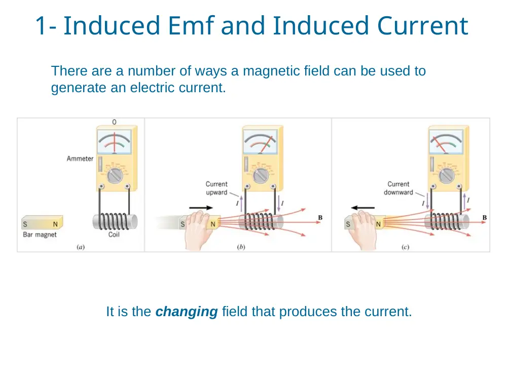
There are a number of ways a magnetic field can be used to
generate an electric current.
It is the changing field that produces the current.
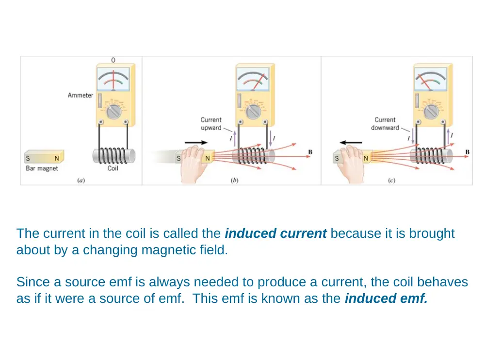
The current in the coil is called the induced current because it is brought
about by a changing magnetic field.
Since a source emf is always needed to produce a current, the coil behaves
as if it were a source of emf. This emf is known as the induced emf.
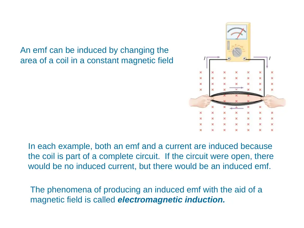
An emf can be induced by changing the
area of a coil in a constant magnetic field
In each example, both an emf and a current are induced because
the coil is part of a complete circuit. If the circuit were open, there
would be no induced current, but there would be an induced emf.
The phenomena of producing an induced emf with the aid of a
magnetic field is called electromagnetic induction.
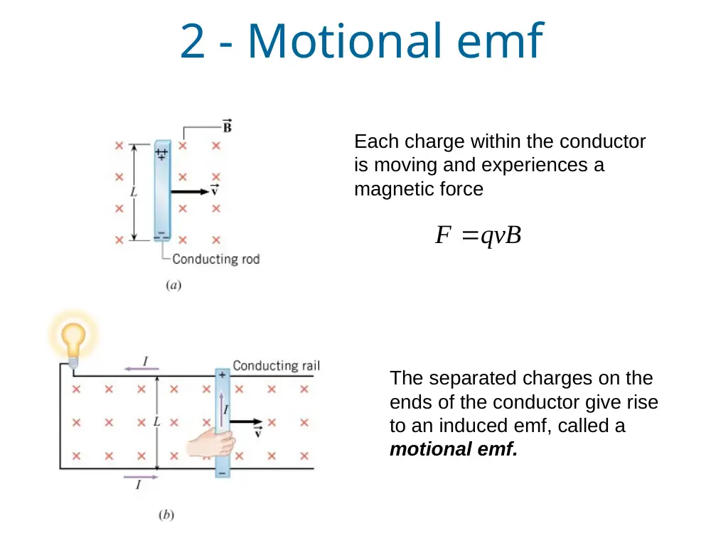
Each charge within the conductor
is moving and experiences a
magnetic force
qvB
F
The separated charges on the
ends of the conductor give rise
to an induced emf, called a
motional emf.
2 - Motional emf
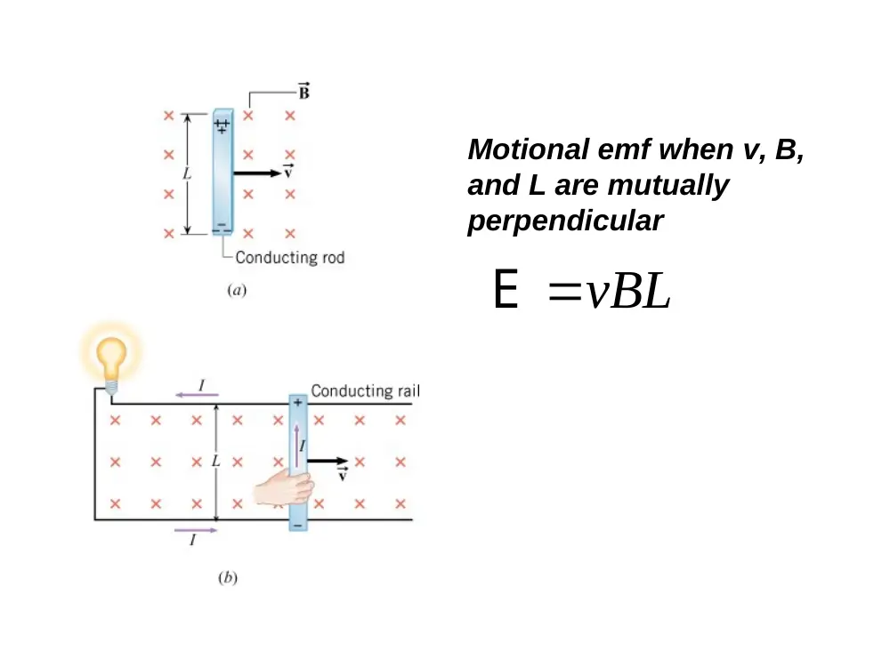
vBL
E
Motional emf when v, B,
and L are mutually
perpendicular
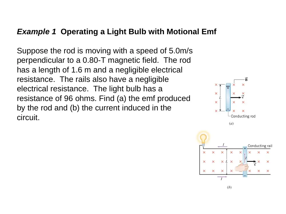
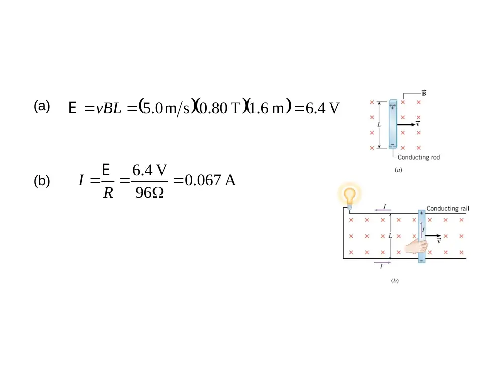
Example 1 Operating a Light Bulb with Motional Emf
Suppose the rod is moving with a speed of 5.0m/s
perpendicular to a 0.80-T magnetic field. The rod
has a length of 1.6 m and a negligible electrical
resistance. The rails also have a negligible
electrical resistance. The light bulb has a
resistance of 96 ohms. Find (a) the emf produced
by the rod and (b) the current induced in the
circuit.
(a)
V
4.6
m
6.1
.0 80 T
m s
0.5
vBL
E
.0 067 A
96
V
4.6
I R
E
(b)
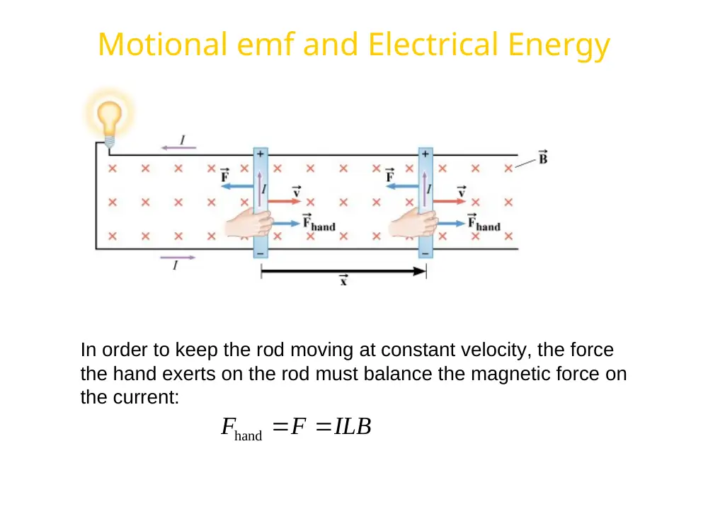
Motional emf and Electrical Energy
In order to keep the rod moving at constant velocity, the force
the hand exerts on the rod must balance the magnetic force on
the current:
ILB
F
F
hand
Conceptual Example 3 Conservation of Energy
A conducting rod is free to slide down between
two vertical copper tracks. There is no kinetic
friction between the rod and the tracks. Because
the only force on the rod is its weight, it falls with
an acceleration equal to the acceleration of
gravity.
Suppose that a resistance connected between the
tops of the tracks. (a) Does the rod now fall with
the acceleration of gravity? (b) How does the
principle of conservation of energy apply?
3- Magnetic Flux
The Magnetic flux is defined as:
cos
B
B A
B A
is the angle between B
and the normal to the
plane.
A is the area of the loop.
B is the magnetic force.
•
When the field is perpendicular to the plane of the loop, as in a, θ = 0
and ΦB = ΦB, max = BA
•
When the field is parallel to the plane of the loop, as in b, θ = 90° and ΦB
= 0
•
The flux can be negative, for example if θ = 180°
•
SI units of flux are T m² = Wb (Weber)
4- Faraday’s law of electromagnetic
induction
If a circuit contains N
tightly wound loops
and the flux changes
by during a time
interval t, the
average emf induced
is given by
Faraday’s Law:
B
N
t
Example 5 The Emf Induced by a Changing Magnetic Field
A coil of wire consists of 20 turns each of which has an area of 0.0015 m2.
A magnetic field is perpendicular to the surface. Initially, the magnitude of
the magnetic field is 0.050 T and 0.10s later, it has increased to 0.060 T.
Find the average emf induced in the coil during this time.
10 V
0.3
s
0.10
.0 050 T
.0 060 T
cos 0
.0 0015 m
20
cos
cos
cos
3
2
t
B
B
NA
t
B A
N BA
t
N
o
o
E
5 - Lenz’ Law
Currents are produced in the loop to counteract changes in flux.
Conceptual Example 9 The Emf Produced
by a Moving Copper Ring.
There is a constant magnetic field directed
into the page in the shaded region. The field
is zero outside the shaded region. A copper
ring slides through the region.
For each of the five positions, determine whether
an induced current exists and, if so, find its
direction.
6 – Applications of Electromagnetic Induction to the
Reproduction of Sound
7- The Electric Generator
BLvsin
v BL
E
2
W
r
v
Emf induced in a rotational planar coil
t
t
NAB
o
sin
sin
E
E
f
2
t
o
E E sin
The Electrical energy delivered and the
countertorque
When the generator is delivering current, there is a magnetic
force
acting on the coils.
The magnetic force gives rise to a
countertorque that opposes the
rotational motion.
The back emf generated by an electric motor
When a motor is operating, two sources of emf are present: (1) the
applied emf V that provides current to drive the motor, and (2) the
emf induced by the generator-like action of the rotating coil.
R
V
I
E
Consistent with Lenz’s law, the induced emf acts to oppose the
applied emf and is called back emf.
Example 12 Operating a Motor
The coil of an ac motor has a resistance of 4.1 ohms. The motor is
plugged into an outlet where the voltage is 120.0 volts (rms), and the coil
develops a back emf of 118.0 volts (rms) when rotating at normal
speed. The motor is turning a wheel. Find (a) the current when the
motor first starts up and (b) the current when the motor is operating at
normal speed.
29 A
4.1
0 V
120 V
R
V
I
E
(a)
.0 49 A
4.1
120 V 118 0. V
R
V
I
E
(b)
8- Mutual Inductance and Self-
inductance
The changing current in the primary coil creates a changing
magnetic flux through the secondary coil, which leads to an
induced emf in the secondary coil.
The effect in called
mutual induction.
t
N
E
Emf due to mutual induction
t
I
M
p
sE
mutual inductance
SI Unit of mutual inductance:
1H (Henry)
1V s A
The effect in which a changing current in a circuit induces and emf
in the same circuit is referred to as self induction.
Self-Inductance
SI Unit of self inductance:
1H (Henry)
1V s A
t
I
L
E
self inductance
The energy stored in an inductor
Energy stored in
an inductor
Energy density
2
2
1
Energy
LI
2
2
1
Energy density
B
o
9- Transformers
A transformer is a device for increasing or decreasing an ac
voltage.
t
N
s
sE
t
N
p
pE
p
s
p
s
N
E N
E
p
s
p
s
N
N
V
V
Transformer
equation
s
p
s
p
p
s
N
N
V
V
I
I
A transformer that steps up the voltage simultaneously
steps down the current, and a transformer that steps down
the voltage steps up the current.