
EECE 210 Lecture 4, Fall 2014
American University of Beirut · Electric Circuits · 35 pages





Showing the first 10 of 35 pages. Download the PDF to see all of it.
More EECE 210 files
Show the text of this lab
Chapter 4
Circuit Theorems
Objective and Overview
The Chapter presents some theorems that apply to electric circuits, and which
center primarily around Thevenin’s theorem.
Thevenin’s theorem takes circuit equivalence to its extreme, by representing
any LTI circuit, between any two given terminals, by a linear-output voltage source in
the case of resistive circuits. Thevenin’s theorem is arguably the most important
theorem in circuit analysis, both from theoretical and practical viewpoints. It is
therefore discussed at length with several examples that highlight some of its
aspects.
The discussion of Thevenin’s equivalent circuit is naturally followed by a
discussion of its current-source counterpart, namely, Norton’s equivalent circuit.
Norton’s equivalent circuit has the added significance that some circuits may have a
Norton’s equivalent circuit, but not a Thevenin’s equivalent circuit, just as the
converse is also true.
The Chapter ends with the substitution theorem, which is a useful theorem
that simplifies the analysis of some types of circuits, and which can be readily proved
using Thevenin’s theorem. A particular form of the substitution theorem, the source
absorption theorem, is presented as a useful tool for replacing dependent sources by
resistors in some cases, which again simplifies circuit analysis in these cases.
Discussion in this Chapter and in Chapters 5 and 6 is restricted to the dc
state.
4.1
Excitation by Dependent Sources
Before presenting Thevenin’s theorem, the following concept is discussed:
Concept: Dependent sources alone do not excite a stable circuit.
To illustrate this concept, consider the
circuit of Figure 4.1.1. From KCL at the upper
essential node, iY + 2IY = vX/6, or,
vX = 18iY
(4.1.1)
From KVL around the mesh on the left,
3vX – 4iY – vX = 0, or,
vX = 2iY
(4.1.2)
Substituting for iY from Equation 4.1.2 in Equation 4.1.1,
vX = 9vX,
or,
8vX = 0
(4.1.3)
It follows that vX = 0, which also makes iY = 0.
This material is copyrighted and must
not be reproduced or distributed.
1-4
–
+
–
+
vX
iY
3vX
2iY
4
6
Figure 4.1.1
Although demonstrated for a particular circuit, it is true in general that if
dependent sources are the only sources in a circuit, the circuit is relaxed, that is, all
voltages and currents in the circuit are zero. An exception is encountered in circuits
with a strong enough positive feedback. These circuits are unstable in that their
responses are unbounded, that is, their magnitudes increase with time until they are
limited by some nonlinearity in the circuit. Such circuits are not of interest to us in this
book. That is the reason for the ‘stable’ qualifier in the statement of the concept
enunciated at the beginning of this section.
Although they alone do not excite a circuit, dependent sources do, of course,
affect the voltages and currents in the circuit. They can deliver or absorb energy, just
like independent sources. It will be shown later (Section 5.1, Chapter 5) that
dependent sources effectively modify the values of some resistances in the circuit.
4.2
Thevenin’s Theorem
In the context of resistive circuits, Thevenin’s theorem can be stated as
follows:
Statement: A circuit consisting of ideal resistors and sources is equivalent, at
a specified pair of terminals, to a linear-output voltage source.
The equivalent circuit, consisting of an ideal voltage source in series with a
resistor is known as Thevenin’s equivalent circuit (TEC). The open-circuit voltage is
referred to as the Thevenin voltage, VTh, and the source resistance as the Thevenin
resistance, RTh. The open-circuit voltage and source resistance were defined for a
linear-output voltage source in Section 3.6, Chapter 3.
Thevenin’s theorem takes circuit equivalence to the extreme, in that it
reduces any LTI circuit at a given pair of terminals to the simplest possible n
equivalent, namely an ideal voltage source in series with a resistor.
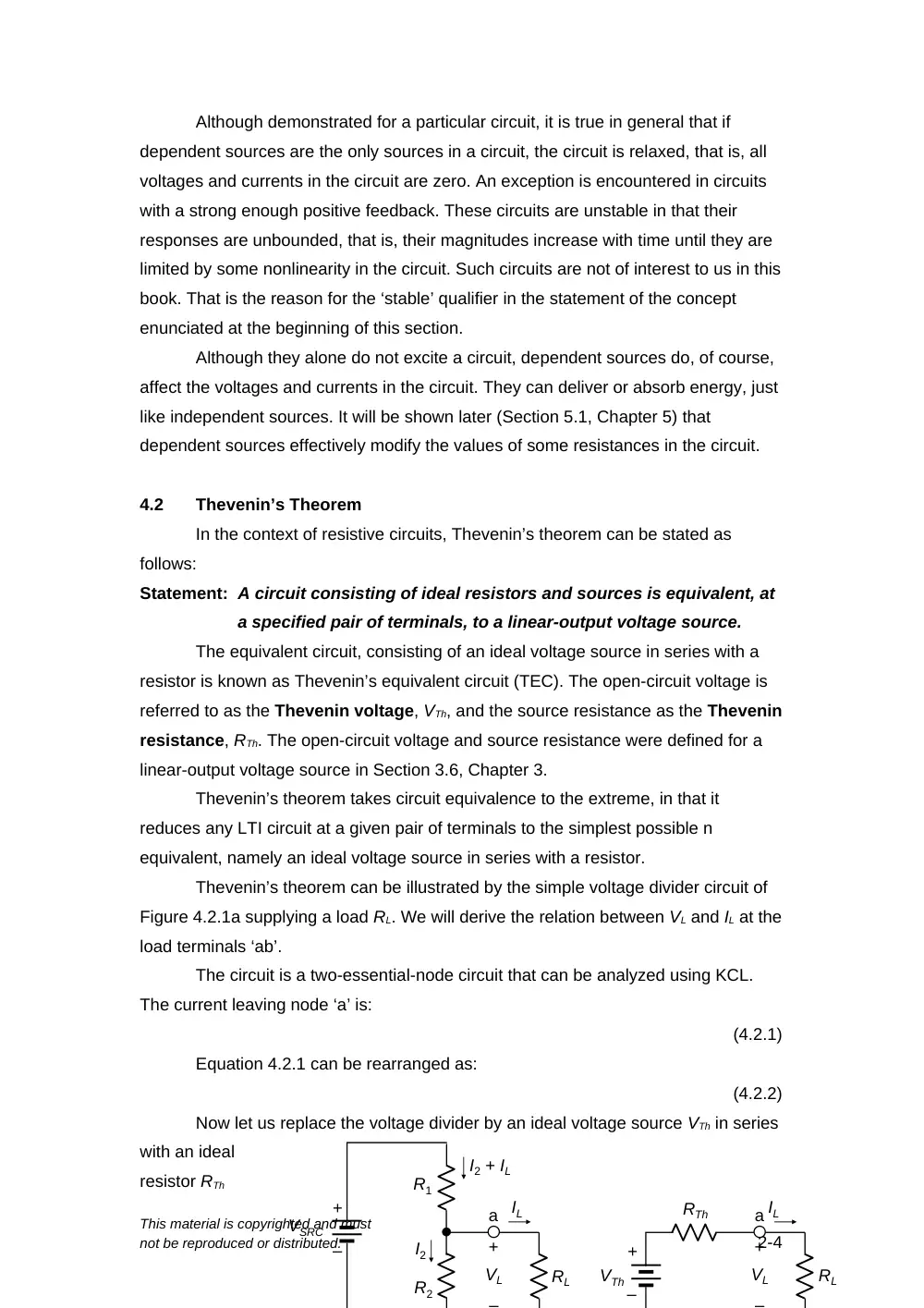
Thevenin’s theorem can be illustrated by the simple voltage divider circuit of
Figure 4.2.1a supplying a load RL. We will derive the relation between VL and IL at the
load terminals ‘ab’.
The circuit is a two-essential-node circuit that can be analyzed using KCL.
The current leaving node ‘a’ is:
(4.2.1)
Equation 4.2.1 can be rearranged as:
(4.2.2)
Now let us replace the voltage divider by an ideal voltage source VTh in series
with an ideal
resistor RTh
This material is copyrighted and must
not be reproduced or distributed.
2-4
+
–
VSRC
R1
–
+
VL
I2 + IL
I2
IL
a
R2
RL
–
+
VL
IL
a
RL
+
–
VTh
RTh
(Figure 4.2.1b). KVL gives:
(4.2.3)
Equation 4.2.3 is of the same form as Equation 4.2.2,
in accordance with Thevenin’s theorem. Moreover, the two equations become
identical if VTh and RTh are given by:
and
(4.2.4)
Under these conditions, VTh in series with RTh is equivalent to the voltage
divider circuit at terminals ‘ab’, since they have the same VL-IL relation (Figure
4.2.1c). RTh is the source resistance, and VTh is the open-circuit voltage at terminals
‘ab’, when IL = 0.
Although shown to apply for the voltage divider circuit, Thevenin’s theorem in
fact applies to a circuit of any complexity consisting of ideal sources and resistors.
Evidently, replacing a complex circuit by its TEC between a given pair of terminals
greatly simplifies analysis of the overall circuit, as will be demonstrated on many
occasions.
Derivation of TEC
In the preceding discussion VTh and RTh were determined by deriving the VL-IL
relation at the given pair of terminals, which is unnecessarily complicated. A simpler
procedure is suggested by the nature of TEC itself and the VL-IL relation. Since the
plot of VL vs. IL is a straight line (Figure 4.2.1c), this line is uniquely determined by
specifying its slope, whose magnitude is Rsrc, and a point through which the line
passes, such as the intercept on the voltage axis. This intercept is VTh and equals VL,
when IL = 0. It can, therefore, be determined directly from the circuit as the open-
circuit voltage at terminals ‘ab’. Thus, if RL is removed from the circuit (Figure 4.2.2a),
it follows from voltage division that:
(4.2.5)
which is the same as Equation 4.2.4.
RTh can be determined in one of two ways: either directly, or as the ratio of the
voltage intercept VTh in Figure 4.2.1c to the current intercept, which is the short-circuit
current ISC. When
terminals ‘ab’ are
short-circuited
(Figure 4.2.2b), it
follows from Ohm’s
law that:
(4.2.6)
This material is copyrighted and must
not be reproduced or distributed.
3-4
+
–
VSRC
R1
–
+
VTh
I2
(a)
(b)
I2
IL = 0
a
b
R2
+
–
VSRC
R1
ISC
I2 = 0
a
b
R2
ISC
Figure 4.2.2
Figure 4.2.3
(a)
(b)
IT
a
RTh
+
–
VT
b
IT
a
RTh
b
+
–
VT
The ratio VTh/ISC is, from Equations 4.2.5 and 4.2.6, R1R2/(R1 + R2), the same
as the expression for RTh in Equation 4.2.4.
The direct method of
determining RTh is suggested
by Figure 4.2.1b. If VTh is set
to zero, that is, replaced by a
short-circuit (Section 2.4,
Chapter 2) and a test voltage
source VT is applied between terminals ‘ab’, then RTh = VT/IT (Figure 4.2.3a). That is,
RTh is Req seen by the test source between terminals ‘ab’. Alternatively, a test current
source IT may be applied and RTh is again given by VT/IT (Figure 4.2.3b). But what
does setting VTh to zero imply in the original circuit? It implies setting all
independent
sources
to zero
, for this removes excitation from the circuit and reduces all currents
and voltages in the circuit to zero, including VTh. As mentioned in Section 4.1,
dependent sources alone do not excite the circuit. Hence, VTh becomes zero when all
independent sources are set to zero while leaving dependent sources unchanged.
Note that although dependent sources alone do not excite the circuit, they do affect
the relations between voltages and currents in the circuit in the presence of
independent sources by effectively altering the values of resistances, including RTh .
Setting dependent sources to zero will therefore alter RTh, whereas setting
independent sources to zero removes excitation from the circuit, without
altering RTh. Bear in mind that an ideal voltage source is set to zero by replacing it
with a short circuit (Section 2.4, Chapter 2), and that an ideal current source is set to
zero by replacing it with an open circuit (Section 2.5, Chapter 2),
It should be noted that applying a test source to determine RTh, as in Figures
4.2.3a and b, is a formal and general method of determining Req between any two
terminals of a circuit, with independent sources set to zero. That was, in fact, the
method used for determining Reqs and Reqp in Chapter 3 (Figures 3.2.1 and 3.2.3).
Using a test source is the only applicable method for determining Req in the presence
of dependent sources. However, In the
absence of dependent sources
, Req, and
hence RTh, can be determined more directly using series/parallel combinations of
resistors, star-delta transformation, etc.
The procedure for deriving TEC can be summarized as follows:
1.
Determine VTh as the open-circuit voltage at the specified terminals.
2.
Determine the short-circuit current ISC at the specified terminals, which gives RTh
as VTh/ISC.
3.
Set all independent sources in the given circuit to zero, leaving dependent
This material is copyrighted and must
not be reproduced or distributed.
4-4
sources unchanged. RTh is the resistance Req looking into the specified terminals.
Formally, this resistance is obtained by applying a test voltage source or a test
current source and determining Req as the ratio of the voltage at the source
terminals to the source current. In the absence of dependent sources, Req can be
derived directly from series/parallel combinations of resistors, and using star-
delta transformations, if necessary.
The following should be noted concerning this procedure:
1.
Since VTh = RThISC, only two of the three quantities in this relation need be
determined through the aforementioned three steps. However, it is useful for
checking purposes to determine all three of these quantities independently.
2.
Moreover, some of the aforementioned three steps many be easier to implement
than others. Thus, setting independent sources to zero can make the circuit
particularly simple.
3.
In some cases, VTh = 0, which means that ISC = 0. It follows that VTh/ISC is 0/0,
which is indeterminate. In this case, RTh can only be determined by Step 3 of the
aforementioned procedure. This is illustrated by Example 4.2.3.
4.
A potential ambiguity in deriving TEC at a pair of terminals is whether or not to
include in TEC a resistor R that is connected between the given pair of terminals.
The ambiguity is resolved in this book by the way the resistor is drawn with
respect to the given terminals or by the way TEC is required. In Figure 4.2.4a, for
example, R is drawn
beyond the terminals at
which TEC is required,
as was done
in Figure 4.2.1a. The
implication is that R
should not be included
in TEC. Even without
drawing the terminals in this manner, requiring “TEC seen by R”, or “TEC looking
into terminals ‘ab’” means that R should not be included in TEC. On the other
hand, if the given terminals are beyond ‘R’, as in Figure 4.2.4b, the implication is
that R should be included in TEC. Requiring “TEC between terminals ‘ab’” is
unambiguous in this case.
5.
Even in the case of Figure 4.2.4b, it may be advantageous to remove R and
determine an intermediate TEC from the simpler circuit that results when R is
removed. After obtaining this TEC, R is connected to the terminals of this TEC
and the final TEC derived. This procedure is illustrated by Example 4.2.4.
This material is copyrighted and must
not be reproduced or distributed.
5-4
a
R
b
(a)
(b)
Figure 4.2.4
Circuit N
a
R
b
Circuit N
Derivation of TEC with PSpice
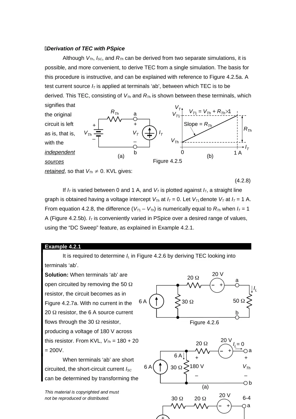
Although VTh, ISC, and RTh can be derived from two separate simulations, it is
possible, and more convenient, to derive TEC from a single simulation. The basis for
this procedure is instructive, and can be explained with reference to Figure 4.2.5a. A
test current source IT is applied at terminals ‘ab’, between which TEC is to be
derived. This TEC, consisting of VTh and RTh is shown between these terminals, which
signifies that
the original
circuit is left
as is, that is,
with the
independent
sources
retained, so that VTh 0. KVL gives:
(4.2.8)
If IT is varied between 0 and 1 A, and VT is plotted against IT, a straight line
graph is obtained having a voltage intercept VTh at IT = 0. Let VT1 denote VT at IT = 1 A.
From equation 4.2.8, the difference (VT1 – VTh) is numerically equal to RTh when IT = 1
A (Figure 4.2.5b). IT is conveniently varied in PSpice over a desired range of values,
using the “DC Sweep” feature, as explained in Example 4.2.1.
Example 4.2.1
It is required to determine IL in Figure 4.2.6 by deriving TEC looking into
terminals ‘ab’.
Solution: When terminals ‘ab’ are
open circuited by removing the 50
resistor, the circuit becomes as in
Figure 4.2.7a. With no current in the
20 resistor, the 6 A source current
flows through the 30 resistor,
producing a voltage of 180 V across
this resistor. From KVL, VTh = 180 + 20
= 200V.
When terminals ‘ab’ are short
circuited, the short-circuit current ISC
can be determined by transforming the
This material is copyrighted and must
not be reproduced or distributed.
6-4
(a)
IT
a
RTh
b
+
–
VT
+
–
VTh
(b)
IT
VTh
Slope = RTh
1 A
0
VT1 = VTh + RTh1
VT
Figure 4.2.5
RTh
VT1
6 A
20
30
–
+
20 V
a
b
(a)
IL= 0
+
–
VTh
+
–
180 V
6 A
20
30
–
+
20 V
a
+
6 A
20
30
–
+
20 V
50
a
b
Figure 4.2.6
IL
ideal 6 A source in parallel with 30 to an ideal voltage source of 306 = 180 V in
series with 30 , as in Figure 4.2.7b. ISC now flows through the 30 and 20
resistors. Applying KVL, starting from node ‘b’ and going clockwise: 180 – 30ISC –
20ISC + 20 = 0. This gives ISC = 200/50 = 4 A. It follows that RTh = VTh/ISC = 200/4 = 50
.
Since the circuit does not have dependent sources, it is not necessary to
apply a test source and determine the ratio of the voltage of the test source to the
current through the source. RTh can be determined in this case as Req between
terminals ‘ab’, or Rin, the input resistance looking into terminals ‘ab’, with independent
sources set to zero.
The 20 V source is
replaced by a short
circuit and the 6 A
source is replaced by
an open circuit, as in
Figure 4.2.8a.
The resistance looking into terminals ‘ab’ is seen to be 30 + 20 = 50 , as
determined previously. TEC between terminals ‘ab’ is therefore a 200 V source in
series with 50 (Figure
4.2.8b). When the 50
resistor is connected
between terminals ‘ab’ IL is
given by: IL = 200/(50 + 50)
= 2 A.
Simulation: The circuit is
entered as in
Figure 4.2.9.
An IDC I2 is
connected
between
terminals ‘ab’
of the circuit.
Its default
value of 0A
need not be
changed. A
voltage
This material is copyrighted and must
not be reproduced or distributed.
7-4
0A
0.5A
1.0A
200V
220V
240V
250V
Test current
VT
Figure 4.2.10
20
30
a
b
Figure 4.2.8
(a)
50
a
b
(b)
200 V
–
+
Rin
50
IL
6Adc
I2
0Adc
20Vdc
30
20
0
Figure 4.2.9
+
_
+
-
V
+
-
a
b
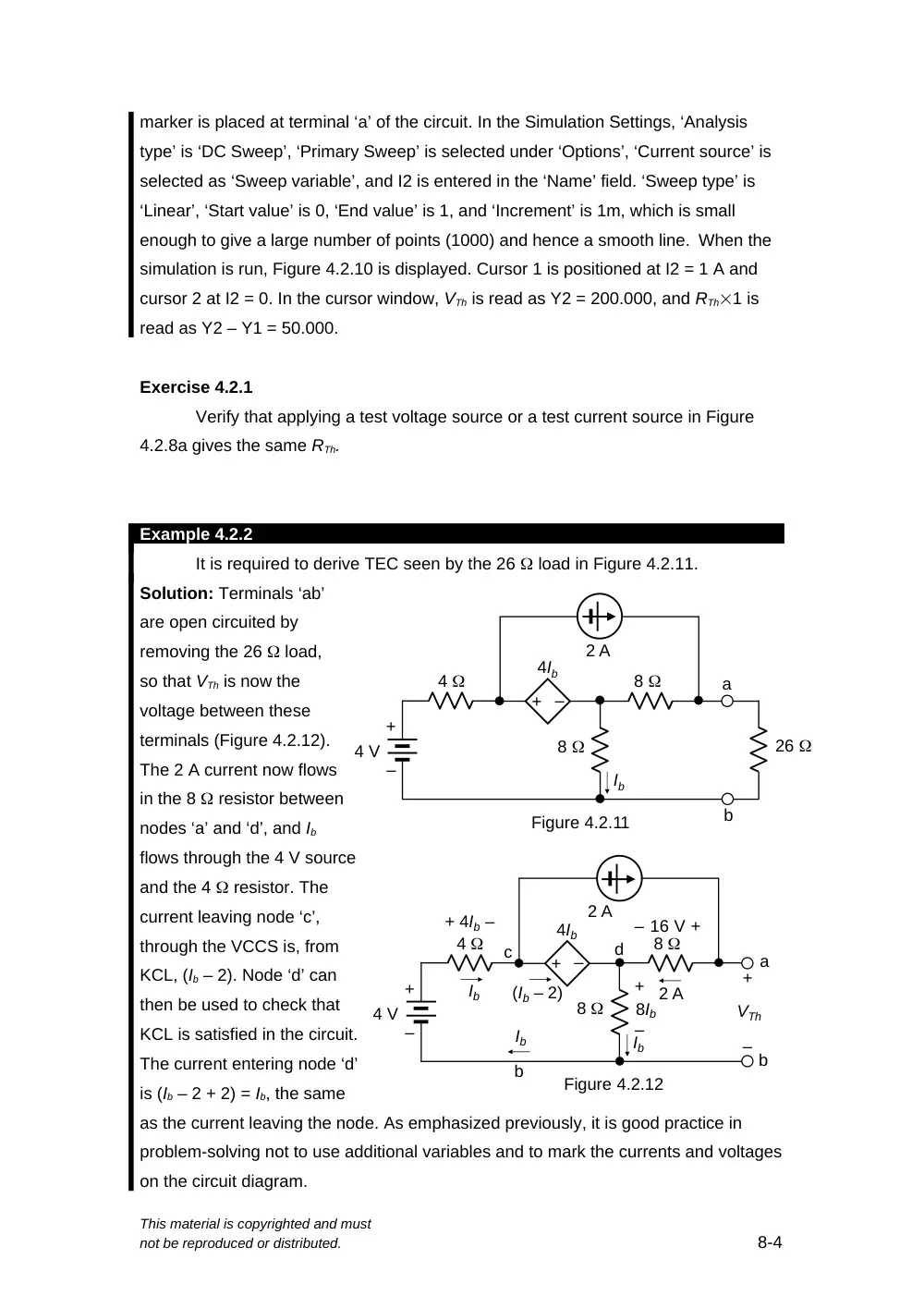
marker is placed at terminal ‘a’ of the circuit. In the Simulation Settings, ‘Analysis
type’ is ‘DC Sweep’, ‘Primary Sweep’ is selected under ‘Options’, ‘Current source’ is
selected as ‘Sweep variable’, and I2 is entered in the ‘Name’ field. ‘Sweep type’ is
‘Linear’, ‘Start value’ is 0, ‘End value’ is 1, and ‘Increment’ is 1m, which is small
enough to give a large number of points (1000) and hence a smooth line. When the
simulation is run, Figure 4.2.10 is displayed. Cursor 1 is positioned at I2 = 1 A and
cursor 2 at I2 = 0. In the cursor window, VTh is read as Y2 = 200.000, and RTh1 is
read as Y2 – Y1 = 50.000.
Exercise 4.2.1
Verify that applying a test voltage source or a test current source in Figure
4.2.8a gives the same RTh.
Example 4.2.2
It is required to derive TEC seen by the 26 load in Figure 4.2.11.
Solution: Terminals ‘ab’
are open circuited by
removing the 26 load,
so that VTh is now the
voltage between these
terminals (Figure 4.2.12).
The 2 A current now flows
in the 8 resistor between
nodes ‘a’ and ‘d’, and Ib
flows through the 4 V source
and the 4 resistor. The
current leaving node ‘c’,
through the VCCS is, from
KCL, (Ib – 2). Node ‘d’ can
then be used to check that
KCL is satisfied in the circuit.
The current entering node ‘d’
is (Ib – 2 + 2) = Ib, the same
as the current leaving the node. As emphasized previously, it is good practice in
problem-solving not to use additional variables and to mark the currents and voltages
on the circuit diagram.
This material is copyrighted and must
not be reproduced or distributed.
8-4
+
–
8
8
2 A
4 V
4
–
+
Ib
4Ib
a
b
+
–
VTh
2 A
Ib
Ib
(Ib – 2)
c
d
Figure 4.2.12
b
+ 4Ib –
16 V
+
+
–
8Ib
–
+
–
8
8
26
2 A
4 V
4
–
+
Ib
4Ib
Figure 4.2.11
a
b
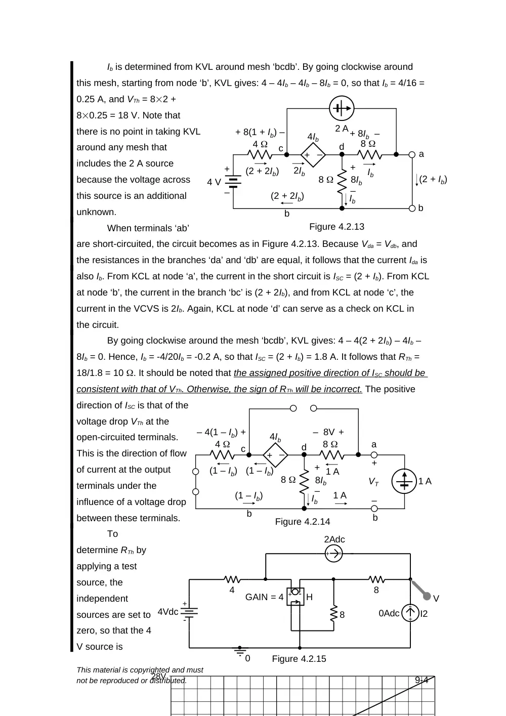
Ib is determined from KVL around mesh ‘bcdb’. By going clockwise around
this mesh, starting from node ‘b’, KVL gives: 4 – 4Ib – 4Ib – 8Ib = 0, so that Ib = 4/16 =
0.25 A, and VTh = 82 +
80.25 = 18 V. Note that
there is no point in taking KVL
around any mesh that
includes the 2 A source
because the voltage across
this source is an additional
unknown.
When terminals ‘ab’
are short-circuited, the circuit becomes as in Figure 4.2.13. Because Vda = Vdb, and
the resistances in the branches ‘da’ and ‘db’ are equal, it follows that the current Ida is
also Ib. From KCL at node ‘a’, the current in the short circuit is ISC = (2 + Ib). From KCL
at node ‘b’, the current in the branch ‘bc’ is (2 + 2Ib), and from KCL at node ‘c’, the
current in the VCVS is 2Ib. Again, KCL at node ‘d’ can serve as a check on KCL in
the circuit.
By going clockwise around the mesh ‘bcdb’, KVL gives: 4 – 4(2 + 2Ib) – 4Ib –
8Ib = 0. Hence, Ib = -4/20Ib = -0.2 A, so that ISC = (2 + Ib) = 1.8 A. It follows that RTh =
18/1.8 = 10 . It should be noted that the assigned positive direction of ISC should be
consistent with that of VTh. Otherwise, the sign of RTh will be incorrect. The positive
direction of ISC is that of the
voltage drop VTh at the
open-circuited terminals.
This is the direction of flow
of current at the output
terminals under the
influence of a voltage drop
between these terminals.
To
determine RTh by
applying a test
source, the
independent
sources are set to
zero, so that the 4
V source is
This material is copyrighted and must
not be reproduced or distributed.
9-4
+
–
8
8
2 A
4 V
4
–
+
Ib
4Ib
a
b
2Ib
c
d
Figure 4.2.13
b
Ib
(2 + Ib)
(2 + 2Ib)
(2 + 2Ib)
+ 8(1 + Ib) –
+ 8Ib –
+
–
8Ib
8
8
4
–
+
Ib
4Ib
a
b
+
–
VT
1 A
(1 – Ib)
c
d
Figure 4.2.14
b
1 A
1 A
(1 – Ib)
(1 – Ib)
– 4(1 – Ib) +
– 8V +
+
–
8Ib
4Vdc
4
8
8
0
GAIN = 4
2Adc
I2
0Adc
V
H
+ -
+
-
Figure 4.2.15
+
-
+
-
28V
Figure 4.2.17
+
–
5 V
25
10
30
15
20
b
c
d
(a)
+
–
5 V
30
20
a
b
c
d
(b)
+
–
+
–
3 V
3 V
10
15
replaced by a short circuit and the 2 A source by an open circuit, as shown in Figure
4.2.14. With a 1 A test source applied, KCL
is satisfied at node ‘d’ by having a current (1 – Ib) leaving this node through the VCVS
and the 4 resistor. Node ‘b’ can be used to check KCL. By going clockwise around
the mesh ‘bcdb’, KVL gives: 4(1 – Ib) – 4Ib – 8Ib = 0. Hence, Ib = 4/16 = 0.25 A, and VT
= 81 + 80.25 = 10 V. It follows that RTh = (10 V)/(1 A) = 10 , as before.
Simulation: The circuit is entered as in Figure 4.2.15. Proceeding as in Example
4.2.1, Figure 4.2.16 is displayed when the simulation is run. It is seen that VTh = 18 V
and RTh = 10 .
Problem-Solving Tip
In deriving TEC, the assigned positive direction of ISC should be in the direction of
the voltage drop VTh so as to obtain the correct sign of RTh = VTh/ISC.
Exercise 4.2.2
Determine RTh in Figure 4.2.14 by applying a 1 V test source rather than a 1 A
source.
Example 4.2.3
It is required to derive TEC seen by the 25 resistor in Figure 4.2.17a.
Solution: As mentioned previously, the circuit configuration is a bridge circuit, since
the 25 resistor between nodes ‘c’ and ‘d’ is a “crossover” element, like a bridge. To
derive TEC seen by the 25 resistor, the resistor is removed and Vbc determined
(Figure 4.2.17b). The voltages Vbd and Vcd in
Figure 4.2.17b can be determined from
voltage division, since the 10 resistor is in series with the 15 resistor, and the 20
resistor is in series with the 30 resistor. Hence, Vbd = 530/(20 + 30) = 3 V, and
Vcd = 515/(10 + 15) = 3 V.
When the two middle nodes of the bridge circuit are at the same voltage, that
This material is copyrighted and must
not be reproduced or distributed.
10-4
is, Vbd = Vcd, the bridge is said to be “balanced”, as will be discussed more fully in
Appendix 5A,
Chapter 5.
With the
bridge balanced, VTh
= Vbc = Vbd – Vcd = 0.
Moreover, when
nodes ‘b’ and ‘c’ are
at the same voltage,
then the current
through any resistor
connected between
these nodes is zero, because there is no voltage to drive such a current. The current
remains zero as the resistance is reduced to zero, that is, when nodes ‘b’ and ‘c’ are
short circuited. It follows that ISC = 0.
However, having VTh and ISC equal to
zero does not mean that RTh = 0,
because RTh = VTh/ISC is indeterminate
and could be finite.
To determine RTh, therefore, the
resistance looking into terminals ‘bc’
should be derived, with the independent
voltage source set
to zero, that is,
replaced by a short-
circuit (Figure
4.2.18a). To make it
easier to visualize
the connections, it
is helpful to redraw
the circuit as in
Figure 4.2.18b.
Clearly, the
resistance between
nodes ‘c’ and ‘d’ is
(10||15 + 20||30) = 18 . With VTh = 0, TEC reduces to an 18 resistor.
Simulation: The circuit is entered as in Figure 4.2.19. Proceeding as in Example
This material is copyrighted and must
not be reproduced or distributed.
11-4
0A
0.2A
0.4A
0.6A
0.8A
1.0A
0V
5V
10V
15V
20V
Test current
VT
Figure 4.2.20
30
20
a
b
c
d
(a)
10
15
Figure 4.2.18
c
a, d
10
15
30
20
b
(b)
5Vdc
20
10
30
15
0Adc
0
V
+
-
Figure 4.2.19
+
-
4.2.1, Figure 4.2.20 is displayed when the simulation is run. It is seen that VTh = 0
and RTh = 18 .
Example 4.2.4
It is required to determine IX in Figure 4.2.21
using TEC.
Solution: TEC will be derived in two steps. The first
step is to determine TEC as seen by the 3 A source
in parallel with the 6 resistor, as illustrated in
Figure 4.2.22a. The motivation for this step is that
the parallel combination of the 3 A source and the 6
resistor is connected between the terminals
where TEC is required. Under these conditions this
parallel combination can be temporarily removed,
resulting in a considerably simpler circuit for which
an intermediate
TEC can be more
easily derived. The
3 A source is then
be added to this
intermediate TEC
and a new TEC
derived, from which
IX is determined by
adding the 6 resistor.
It is seen from voltage division in Figure 4.2.22a that Vac = 96/9 = 6 V, and
Vbc = 93/9 = 3 V. It follows that VTh1 = Vac – Vbc = 6 – 3 = 3 V. RTh1 is most easily
found by determining the resistance between terminals ‘ab’ with the 9 V source set to
zero, that is, replaced by a short circuit. This makes RTh1 = Rab = (6||3) + (6||3) = 2 + 2
= 4 . The intermediate TEC will therefore consist of VTh1 = 3 V is series with RTh1 = 4
(Figure 4.2.22b).
The next step is to connect the 3 A current source and derive a second TEC
as seen by the 6 resistor (Figure 4.2.23a). The 3A current now flows through the 3
V source and the 4 resistor, so that the open-circuit voltage Vab = VTh2 = 3 + 12 =
This material is copyrighted and must
not be reproduced or distributed.
12-4
Figure 4.2.22
9 V
6
6
3
3
a
b
c
+
–
6 V
+
–
3 V
(a)
4
(b)
+
–
+
–
3 V
a
b
Figure 4.2.21
9 V
6
6
3
3
6
3 A
IX
+
–
15 V. When the 3 A
source is replaced by an
open circuit and the 3 V
source by a short circuit,
the resistance seen
between terminals ‘ab’ is
RTh2 = Rab = 4 as before
(Figure 4.2.23b). When
the 6 resistor is
connected to terminals
‘ab’, IX that flows is 15/(6 +
4) = 1.5 A (Figure 4.2.23c).
Simulation: Although the current IX can be derived
directly by simulating the circuit of Figure 4.2.21
without invoking TEC, it is instructive to derive by
simulation TEC as seen by the 6 resistor. The
circuit is entered as in Figure 4.2.24. Proceeding as in
Example 4.2.1, Figure 4.2.21 is displayed when the
simulation is run. It is seen that VTh = 15 V and RTh = 4
, as
determined
previously.
Problem-
Solving Tips
When a
voltage or a
current in a
circuit is
required, it
can often be
conveniently
determined
by deriving TEC at the terminals associated with this voltage or current.
In deriving TEC it is often advantageous to temporarily remove elements that
appear in parallel or in series with the terminals between which TEC is required,
derive an intermediate TEC, then restore the removed elements to this
intermediate TEC in order to derive the final TEC.
This material is copyrighted and must
not be reproduced or distributed.
13-4
0A
0.2A
0.4A
0.6A
0.8A
1.0A
15V
16V
17V
18V
19V
Test current
VT
Figure 4.2.25
Figure 4.2.24
9Vdc
6
3
0
3
6
3Adc
0Adc
V
+
-
+
-
+
-
Figure 4.2.23
(a)
4
(b)
+
–
3 V
a
b
4
+
–
15 V
a
b
3 A
3 A
+
–
12 V
(c)
4
+
–
15 V
a
b
6
IX
Exercise 4.2.3
Determine RTh in Figure 4.2.22a by deriving ISC.
Primal Exercise 4.2.4
Determine TEC between nodes ‘a’
and ‘b’ in Figure 4.2.26: (a) without including
the 60 resistance between these nodes;
(b) including this resistance.
Ans.
(a) 12 V in series with 30 ;
(b) 8 V in series with 20 .
4.3
Norton’s Theorem
In the context of resistive circuits, Norton’s theorem can be stated as follows:
Statement: A circuit consisting of ideal resistors and sources is equivalent, at
a specified pair of terminals, to a linear-output current source.
It is
seen that
Norton’s
equivalent
circuit (NEC)
is in fact the
linear-
output current
source
equivalent of TEC. The two equivalent circuits are related by source transformation,
as illustrated in Figure 4.3.1. The ideal current source IN is referred to as Norton’s
current and is the short-circuit current of TEC, that is, VTh/RTh, in accordance with
source transformation. The source resistance that is in parallel with IN is Norton’s
resistance RN, and is the same as RTh in TEC.
It is sometimes more convenient to derive NEC rather than TEC, as in
Example 4.3.1. Moreover, some circuits may have an NEC but not a TEC, or
conversely, as in the case of ideal voltage sources and ideal current sources. Thus,
an ideal voltage source can be considered to be its own TEC, with RTh = 0. IN = VTh/0
, which means that NEC does not exist. Similarly, an ideal current source can be
regarded as its own NEC, with RN = , so that VTh , which means that TEC does
not exist. This is in accordance with the fact that an ideal voltage source cannot be
This material is copyrighted and must
not be reproduced or distributed.
14-4
a
RL
+
–
VTh
RTh
b
(a)
(b)
a
b
RL
IN
RN
RTh = RN
VTh = RNIN
Figure 4.3.1
Figure 4.2.26
+
–
20 V
6
60
60
40
a
b
transformed to an ideal current source, and conversely, as explained in Section 3.6,
Chapter 3. Circuits that have TEC but not NEC generally reduce to an ideal voltage
source between the terminals involved, whereas circuits that have NEC but not TEC
generally reduce to an ideal current source between these terminals. Examples of
these are given in the problems at the end of the chapter.
The procedure for deriving NEC is essentially the same as that for TEC.
When independent sources are set to zero in Figure 4.3.1, the ideal voltage source in
TEC is replaced by a short circuit and the ideal current source in NEC is replaced by
an open circuit. The resistance looking into terminals ‘ab’ is RTh = RN in both cases. In
the case of TEC, VTh is generally determined directly, and the short-circuit current, IN,
is determined as an alternative method for finding RTh. In the case of NEC, IN is
generally determined directly, and the open-circuit voltage, VTh, is determined as an
alternative method for finding RN.
Derivation of NEC with PSpice
NEC can
be derived in a
single
simulation,
analogous to
that described
for TEC, and
explained in Figure 4.3.2a. A test source VT is connected between these terminals
with the circuit left as is, that is with the independent sources retained, so that IN 0.
KCL gives:
(4.3.1)
If VT is varied between 0 and 1 V, and IT is plotted against VT, a straight line
graph is obtained having a current intercept IN at VT = 0. The difference between IT1,
which is IT at VT = 1 V, and IN is numerically equal to GN (Figure 4.3.2b). VT is
conveniently varied in PSpice over a desired range of values, using the “DC Sweep”
feature.
Example 4.3.1
It is required to
determine IL in Figure
4.3.3 using NEC.
This material is copyrighted and must
not be reproduced or distributed.
15-4
(a)
+
–
VT
(b)
VT
IN
Slope = GN
1 A
0
IT1 = IN + GN1
IT
Figure 4.3.2
GN
IN
GN
GNVT
IT
IT1
–
–
+
+
15
10
5 A
2VX
VX
IS
3IS
50
IL
Figure 4 3 3
a
b
Solution: When terminals ‘ab’ are short circuited, VX = 0 and the VCVS becomes a
short circuit (Figure 4.3.4a). The 15 and 10 resistors are paralleled. By current
division, the currents in these two resistors are 2 A and 3 A as shown. IS = -2 A and
the CCCS becomes 6 A directed upwards. It follows that ISC = IN = 3 + 6 = 9 A. Note
that the 6 A source
current only adds to the
current in the short
circuit between nodes ‘a’
and ‘b’ in Figure 4.3.4a
and does not affect
current division.
To determine RN,
a test source IT is
applied, with the 5 A
current source replaced
by an open circuit
(Figure 4.3.4b). KVL
gives:
2VT – 25IS –VT = 0,
or
VT = 25IS
(4.3.2)
From KCL, IS + IT = 3IS, or,
IT = 2IS
(4.3.3)
Dividing Equation 4.3.3 by Equation 4.3.2,
(4.3.4)
NEC therefore consists of a 9 A source in parallel with a 12.5 resistor
(Figure 4.3.5a). When the 50 resistor is connected between terminals ‘ab’, it
follows from current division that:
= 1.8 A
(4.3.5)
It may be
noted that
determining the
open-circuit
voltage in Figure
4.3.3 in order to
work with TEC is
slig