
EECE 210 Lecture Circuit Elements, Spring 2012
American University of Beirut · Electric Circuits · 48 pages
Showing the first 10 of 48 pages. Download the PDF to see all of it.
More EECE 210 files
Show the text of this lab
Chapter 2
Circuit Elements
Voltage and current sources
An electrical source is a device that is capable of converting
nonelectric energy to electric energy and vice versa.
A discharging battery converts chemical energy to electric
energy, whereas a battery being charged converts electric
energy to chemical energy.
The important thing to remember about these sources is that
they can either deliver or absorb electric power, generally
maintaining either voltage or current.
An ideal voltage source is a circuit element that maintains a
prescribed voltage across its terminals regardless of the current
flowing in those terminals.
Voltage and current sources
An ideal current source is a circuit element
that maintains a prescribed current through
its terminals regardless of the voltage across
those terminals.
These circuit elements do not exist as
practical devices they are idealized models of
actual voltage and current sources
Dependent or Independent Sources
Ideal voltage and current sources can be either independent
sources or dependent sources.
An independent source establishes a voltage or current in a
circuit without relying on voltages or currents elsewhere in the
circuit. The value of the voltage or current supplied is specified
by the value of the independent source alone.
A dependent source establishes a voltage or current whose
value depends on the value of a voltage or current elsewhere in
the circuit. You cannot specify the value of a dependent source
unless you know the value of the voltage or current on which it
depends.
Ideal Independent Sources
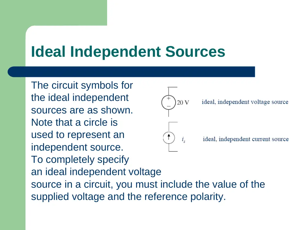
The circuit symbols for
the ideal independent
sources are as shown.
Note that a circle is
used to represent an
independent source.
To completely specify
an ideal independent voltage
source in a circuit, you must include the value of the
supplied voltage and the reference polarity.
Dependent Sources
As for the dependent sources, both the
dependent current and voltage sources
maybe controlled by either a current or a
voltage elsewhere in the circuit, so there are
a total of four variation.
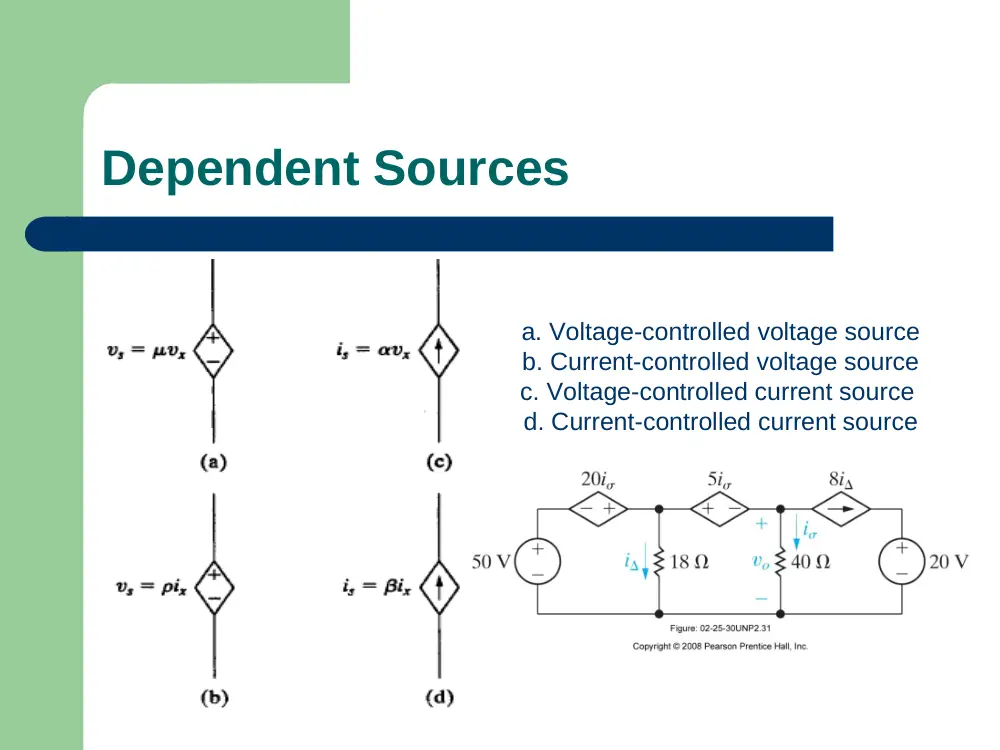
Dependent Sources
a. Voltage-controlled voltage source
b. Current-controlled voltage source
c. Voltage-controlled current source
d. Current-controlled current source
Active and Passive Elements
An active element is one that models a
device capable of generating electric energy.
Passive elements model physical devices
that cannot generate electric energy.
Resistors, inductors, and capacitors are
examples of passive elements.
Electrical Resistance (Ohm's Law)
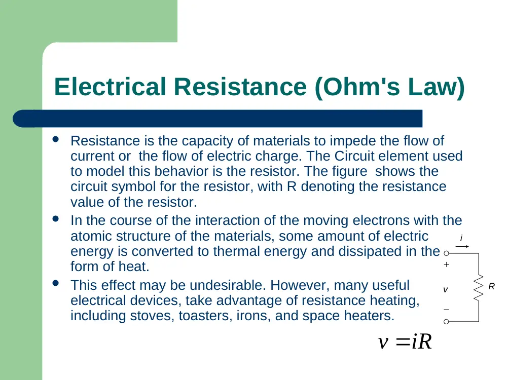
Resistance is the capacity of materials to impede the flow of
current or the flow of electric charge. The Circuit element used
to model this behavior is the resistor. The figure shows the
circuit symbol for the resistor, with R denoting the resistance
value of the resistor.
In the course of the interaction of the moving electrons with the
atomic structure of the materials, some amount of electric
energy is converted to thermal energy and dissipated in the
form of heat.
This effect may be undesirable. However, many useful
electrical devices, take advantage of resistance heating,
including stoves, toasters, irons, and space heaters.
v
R
i
+
–
v iR
Conductance
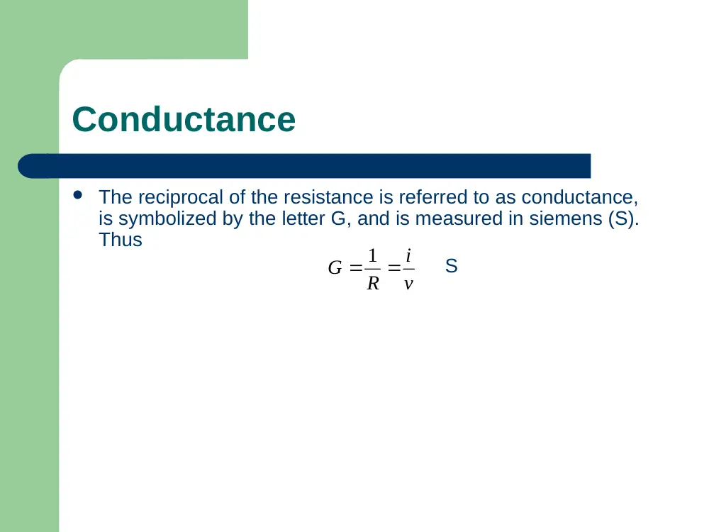
The reciprocal of the resistance is referred to as conductance,
is symbolized by the letter G, and is measured in siemens (S).
Thus
S
v
i
R
G
1
Ohm’s Law
For purposes of circuit analysis, we must
reference the current in the resistor to
the terminal voltage. The relationship
between the voltage and the current is:
v = R i
Where v = the voltage in volts, i = the
current in amperes, and R = the
resistance in ohms (Ω).
Power
We may calculate the power at the terminals of a
resistor in several ways. The first approach is to use the
defining equation and simply calculate the product of
the terminal voltage and current. We write
Pdissipated = vi
A second method of writing the power is in term of
current and resistance:
P= vi = (iR)i=
A third method of writing the power is in term of voltage
and resistance:
P
2
Ri
2
R
v
Power dissipated or generated?
If the current direction through an element
is going through a voltage drop, then
Pdissipated = v.i
If the current direction through an element
is going through a voltage rise, then
Pdissipated = -v.i
If Pdissipated is negative, then that element is
actually generating (not dissipating) power.
Example: Find the Power dissipated by each
element.
V (V)
I (A)
Pdiss (W)
V1=5
I1=2
V2=2
I1=2
V3=-3
I3=-3
V4=-1
I2=1
V5=4
I2=1
+
V1
-
+
V5
-
-
V3
+
+ V2 -
+ V4 -
I3
I1
I2
Example: Find the Power dissipated by each
element.
V (V)
I (A)
Pdiss (W)
V1=5
I1=2
P1diss = -V1*I12=-5*2=-10
→ P1gen = 10w
V2=2
I1=2
P2diss=V2*I1=2*2=4
V3=-3
I3=-3
P3diss=V3*I3=(-3)(-3)=9
V4=-1
I2=1
P4diss=-V4*I2=-(-1)(1)=1
V5=4
I2=1
P5diss=-V5*I2=-(4)(1)=-4
→ P5gen = 4w
+
V1
-
+
V5
-
-
V3
+
+ V2 -
+ V4 -
I3
I1
I2
PTgenerated = 10 + 4 = 14W
PTdissipated = 4 + 9 + 1 = 14W
PTgenerated = PTdissipated
Circuit Terminology
A circuit is an interconnection of circuit elements
that provides one or more closed paths for the flow
of current. A network is generally more complex
than a circuit and can include several simpler
circuits.
A node in a circuit is the junction of two or more
circuit elements. An essential node is the junction of
three or more circuit elements. The definition of a
node includes that of an essential node, but not
conversely. Normally, an essential node is indicated
on circuit diagrams by a filled circle.
Circuit Terminology
A path in a circuit is a set of one or more adjoining circuit
elements that may be traversed in succession without passing
through the same node more than once. A path generally has
an initial node at its beginning and a final node at its end. If the
initial and final nodes are the same, the path is closed and
becomes a loop. A mesh is a loop that does not enclose any
other loop.
A branch is a path that connects two consecutive nodes. An
essential branch is a branch that connects two consecutive
essential nodes (without passing through an essential node). The
definition of a branch includes that of an essential branch, but
not conversely.
Example: Bridge circuit
vSRC
a
b
c
d
1
2
3'
4
R1
R4
R3
R5
R2
–
+
–
+
Rsrc
5
3
1
R
3
R
4
R
Nodes a, b, c, and d are essential
nodes
vSRC
a
b
c
d
1
2
3'
4
R1
R4
R3
R5
R2
–
+
–
+
Rsrc
5
3
1
R
3
R
4
R
Nodes 1, 2 and 4 are not essential
nodes
vSRC
a
b
c
d
1
2
3'
4
R1
R4
R3
R5
R2
–
+
–
+
Rsrc
5
3
1
R
3
R
4
R
Nodes 3 and b are one and the same
because no circuit element is
connected between them
vSRC
a
b
c
d
1
2
3'
4
R1
R4
R3
R5
R2
–
+
–
+
Rsrc
5
3
1
R
3
R
4
R
Nodes 5, d and 3’ are one and the
same because no circuit element is
connected between them
vSRC
a
b
c
d
1
2
3'
4
R1
R4
R3
R5
R2
–
+
–
+
Rsrc
5
3
1
R
3
R
4
R
Rsrc, vSRC, R’1, R1, R’4, R4, R’3, R3,
R2 and R5 taken individually, are
branches
vSRC
a
b
c
d
1
2
3'
4
R1
R4
R3
R5
R2
–
+
–
+
Rsrc
5
3
1
R
3
R
4
R
The combinations Rsrc-VSRC, R’1-R1, R’4-R4,
and the individual branches R’3, R3, R2 and
R5 are essential branches
vSRC
a
b
c
d
1
2
3'
4
R1
R4
R3
R5
R2
–
+
–
+
Rsrc
5
3
1
R
3
R
4
R
The closed paths d-5-1-a-b-d and d-5-1-
a-c-b-d are loops
vSRC
a
b
c
d
1
2
3'
4
R1
R4
R3
R5
R2
–
+
–
+
Rsrc
5
3
1
R
3
R
4
R
The paths d-5-1-a-c-d, a-b-c-a, d-c-b-d
(through R’3) and 3-3’-3 are meshes.
vSRC
a
b
c
d
1
2
3'
4
R1
R4
R3
R5
R2
–
+
–
+
Rsrc
5
3
1
R
3
R
4
R
Kirchhoff’s Laws
There are two Kirchhoff’s laws: Kirchhoff’s
current law (KCL) and Kirchhoff’s voltage
law (KVL). These laws are basic circuit laws
that must be satisfied under all conditions,
because they derive from conservation of
charge and conservation of energy
Kirchhoff’s Current Law
KCL may be stated as follows: at any instant of time,
the sum of currents entering a node is equal to the
sum of currents leaving the node. At node N, for
example, KCL gives: iA + iB = iC + iD. Alternatively, iA +
iB – iC – iD = 0, where currents flowing towards a node
have been arbitrarily assigned a positive sign, which
means that currents flowing away from a node
should be assigned a negative sign.
N
iA
iC
iB
iD
Kirchhoff’s Voltage Law
KVL may be stated as
follows:
At any instant of time,
the sum of the voltage
rises around any loop
is equal to the sum of
the voltage drops around the loop
v1
v5
v2
v4
v3
q
+
+
+
+
+
–
–
–
–
–
+
Kirchhoff’s Voltage Law
An equivalent statement
of KVL is:
At any instant of time,
the algebraic sum of the
voltages around any loop
is zero, since voltage drops and voltage
rises are assigned opposite signs
v1
v5
v2
v4
v3
q
+
+
+
+
+
–
–
–
–
–
+
In the circuit shown, if the loop is traversed
clockwise, then v1, v2, and v3 are voltage
rises, whereas v4 and v5 are voltage drops.
According to the first statement of KVL: v1 +
v2 + v3 = v4 + v5, whereas according to the
second statement v1 + v2 + v3 – v4 – v5 = 0,
which is evidently an equivalent statement.
v1
v5
v2
v4
v3
q
+
+
+
+
+
–
–
–
–
–
+
Example: KVL and KCL
–
–
–
–
–
–
–
+
+
+
+
+
+
+
+
2 V
1 V
1 V
4 V
4.5 V
4.5 V
10 V
3 V
16 V
20
20
10
10
20
0.1 A
0.05 A
200
18
18
0.2 A
0.25 A
0.05 A
–
0.3 A
1
2
3
4
5
6
7
8
–
+
–
+
0.3 A
Find io
Solve
Solve for i0 and i∆
Equivalence of Sources
Independent current sources in parallel add
up (algebraically).
Independent voltage sources in series add up
(algebraically).
Equivalence of Sources
Current sources in series or
voltage sources in parallel are
forbidden unless the sources
are pointing in the same
direction and have exactly the
same values
invalid
valid
valid
State whether the following
connections are valid or not
In each circuit, if the connection is valid, find the power dissipated (or
generated) by each source. If the connection is not valid, explain why.
Find v1 and vg if vo = 250mV (hint: start at vo and
work back toward vg)
P2.30 solution
P2.31 Find i and vo, and show that power
generated (or developed) equals power
dissipated (or absorbed).
Avoid writing KVL
around a mesh or
loop containing a
current source
(unless we need to
find the voltage
across that current
source).
Avoid writing KCL on a
node connected to a
branch containing only
a voltage source
(unless we need to
solve for the current in
that branch).
P2.31 Find i and vo, and show that power
generated (or developed) equals power
dissipated (or absorbed).
50 + 20i -5i -40i =0; i = 2A
P2.31 Find i and vo, and show that power
generated (or developed) equals power
dissipated (or absorbed).
50 + 20 i -18 i =0;
i = 2A, i = 5A
P2.31 Find i and vo, and show that power
generated (or developed) equals power
dissipated (or absorbed).
50 + 20 i -18 i =0;
i = 2A, i = 5A
ig
i1
8i=40A, i1 = 2+40=42A, ig = 5+42=47A
40i -vd -20 =0; vd = 60V
+ vd -
Power dissipated or generated?
If the current direction through an element is
going through a voltage drop, then Pdissipated =
v.i
If the current direction through an element is
going through a voltage rise, then Pdissipated =
-v.i
If Pdissipated is negative, then that element is
actually generating (not dissipating) power.
Pgenerated = Pdissipated
element
v
i
Pdissipated
50V V. source
50V
47A
-50*47= -2350W Pgenerated=2350W
20 i V. source
40V
47A
-40*47= -1880W Pgenerated=1880W
5 i V. source
10V
42A
10*42= 420 W
20V V. source
20V
40A
20*40= 800 W
8 i C. source
60V
40A
60*40= 2400W
18 Resistor
18*5=90V
5A
90*5 = 450W
40 Resistor
40*2=80V
2A
80*2 = 160W
Pdissipated = 420+800+2400+450+160=4230W
Pgenerated = 2350+1880 = 4230W
Pdissipated = Pgenerated