
EECE 210 Lecture, Spring 2012
American University of Beirut · Electric Circuits · 45 pages




Showing the first 10 of 45 pages. Download the PDF to see all of it.
More EECE 210 files
Show the text of this lab
1
Chapter 3
Simple Resistive Circuits
2
Resistors in Series
In a series connection of resistors, the same current
flows through all the resistors, and voltages across the
individual resistors may be added algebraically to
obtain the total voltage across the series combination
R1
R2
Rn
+ v2
–
+ v1
–
vn
+
–
i
+
–
v
+
–
v
i
3
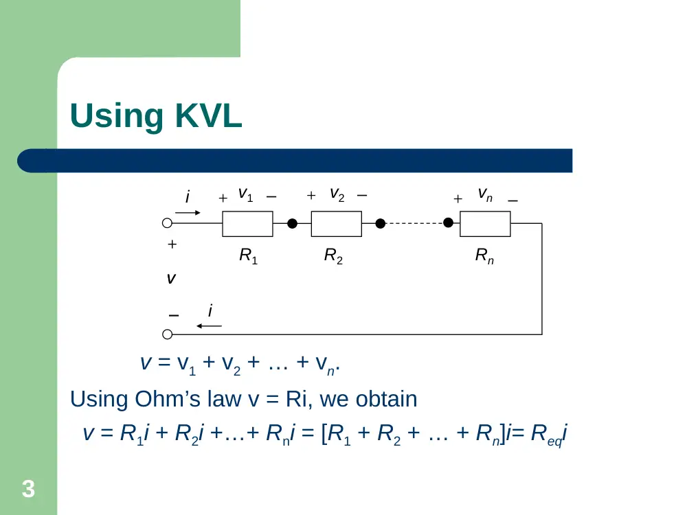
Using KVL
v = v1 + v2 + … + vn.
Using Ohm’s law v = Ri, we obtain
v = R1i + R2i +…+ Rni = [R1 + R2 + … + Rn]i= Reqi
R1
R2
Rn
+ v2
–
+ v1
–
vn
+
–
i
+
–
v
+
–
v
i
4
In general
In general, if k resistors are connected in
series, then
Req = R1 + R2 +… + Rk
5
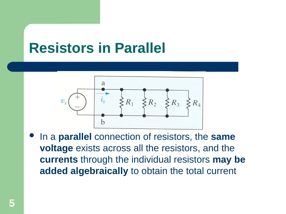
Resistors in Parallel
In a parallel connection of resistors, the same
voltage exists across all the resistors, and the
currents through the individual resistors may be
added algebraically to obtain the total current
6
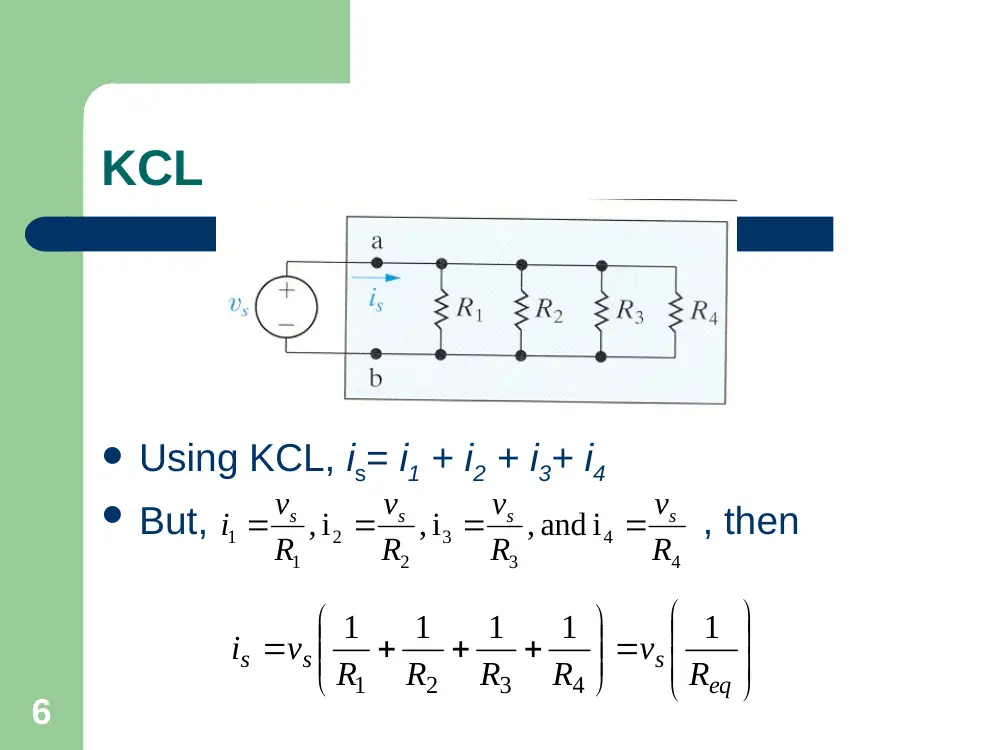
KCL
Using KCL, is= i1 + i2 + i3+ i4
But, , then
4
4
3
3
2
2
1
1
, and i
i ,
i ,
R
v
R
v
R
v
R
v
i
s
s
s
s
eq
s
s
s
R
v
R
R
R
R
v
i
1
1
1
1
1
4
3
2
1
7
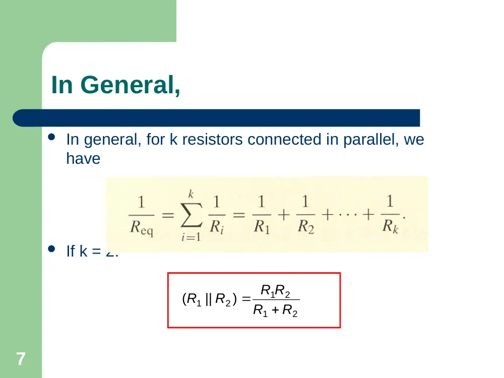
In General,
In general, for k resistors connected in parallel, we
have
If k = 2:
2
1
2
1
2
1
)
(
R
R
R R
R || R
8
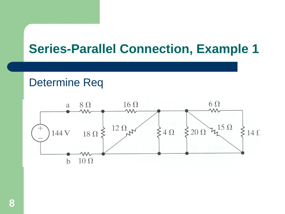
Series-Parallel Connection, Example 1
Determine Req
9
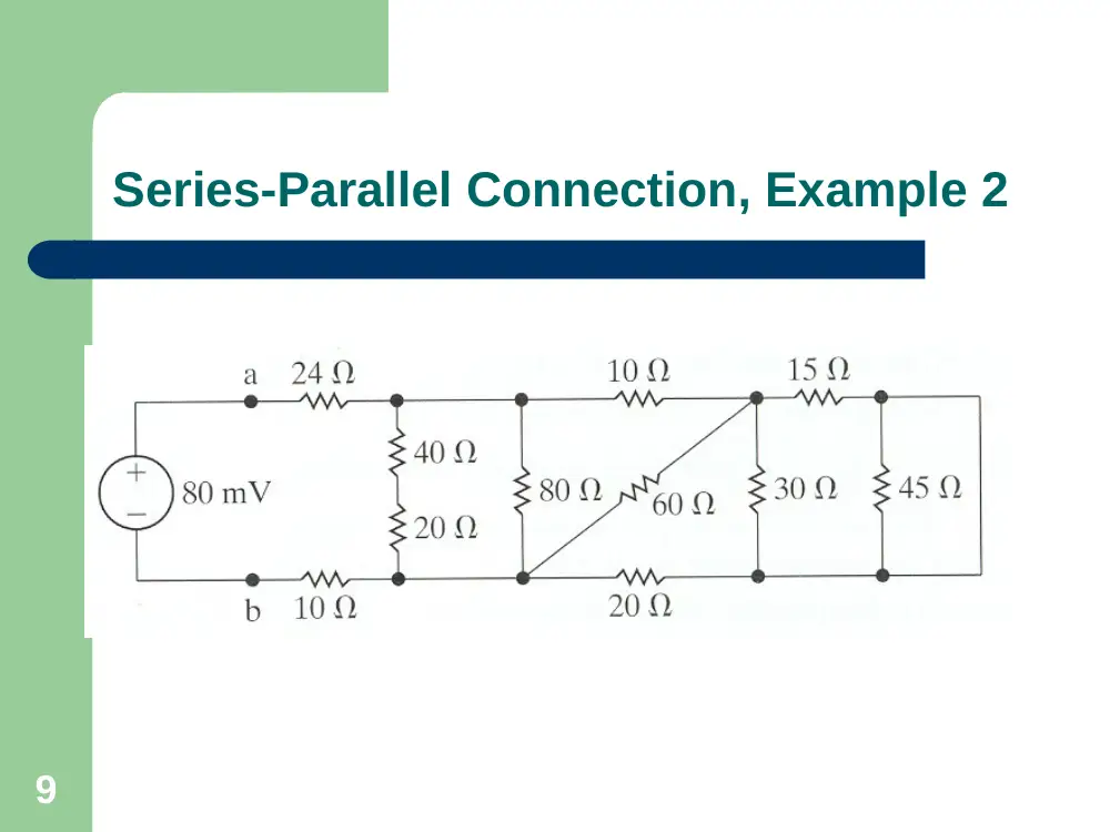
Series-Parallel Connection, Example 2
10
Voltage Divider Rule
Determine Vk ?
1. KCL is satisfied by having a
common current i through
all the resistors
2. From Ohm’s law: vk = Rki,
and vSCR = (R1+ R2 +…+Rk)i
vSRC
R1
i
R2
–
+
Rk
Rn
+
+
v1
v2
–
–
+
vk
–
+
vn
–
11
Voltage Divider Rule
Hence
vSRC
R1
i
R2
–
+
Rk
Rn
+
+
v1
v2
–
–
+
vk
–
+
vn
–
n
k
k
SRC
k
R
R
R
R
R
v
v
...
...
2
1
12
Example: Voltage Divider Rule
If a load RL is
connected across
R2, then
vSRC
R1
+
+
v1
R2
RL
iL
vL
–
+
–
+
–
–
)
||
(
)
||
(
2
1
2
L
L
SRC
L
R
R
R
R
R
v
v
13
Current Divider Rule
– A resistive current divider, consists of two or more resistors
in parallel. In the case of only two resistors, the current i
divides into two components i1 and i2. From KCL: i = i1 +
i2.
– By assigning a common voltage v = vSRC across the three
parallel elements, KVL is automatically satisfied around the
two meshes, one consisting of vSRC and R1 and the other
consisting of R1 and R2. In going around the mesh formed
by R1 and R2, for example, there is a voltage rise vSRC
across one of the resistors and an equal voltage drop vSRC
in the other resistor.
R1
R2
vSRC
–
+
–
+
i1
i2
i
14
Current Divider Rule
From Ohm’s law:
(1)
where
is the parallel resistance of R1 and R2.
Dividing (1) by R1R2, we obtain
(2)
R1
R2
vSRC
–
+
–
+
i1
i2
i
i
R
R
R i
R i
vSRC
)
||
(
2
1
2 2
1 1
2
1
2
1
2
1
)
(
R
R
R R
R || R
2
1
1
2
2
1
R
R
i
R
i
R
i
15
Current Divider Rule
(2)
From (2), we obtain
2
1
1
2
2
1
R
R
i
R
i
R
i
R1
R2
vSRC
–
+
–
+
i1
i2
i
2
1
1
2
2
1
2
1
1
2
1
2
2
1
2
1
R
R
R i
R i
R
R i
i
or
R i
R
R i i
R
i
16
Example
17
Example: Find the voltage across the 4Ω resistor.
18
Example: Find the current through the 12Ω resistor.
19
Measurement of DC Currents and
Voltages
Ammeters. An ammeter is an instrument that
measures current through a circuit element
when inserted in series with that element
Voltmeters. A voltmeter is an instrument that
measures the voltage across a circuit
element.
Example
20
100 identical lamps rated at 12 V, 6 W
each are to be connected across a 240 V
supply such that the rated voltage of 12 V
is applied to each lamp. Design an
appropriate arrangement of the lamps and
calculate the equivalent resistance, the
total current drawn from the supply and the
total power dissipated/generated in the
circuit.
21
Solution: Since 240/12= 20, then 20 lamps may be connected
in series across the supply. The voltage across each lamp will
be the rated voltage of 12 V, assuming the lamp resistances
are all equal. To accommodate 100 lamps, 5 such series
combinations will have to be paralleled across the supply. The
resistance of each lamp is R=v2/P=122/6=24 . The equivalent
series resistance of 20 lamps is 2420 = 480. The equivalent
parallel resistance of five of these series combinations is
480/5=96. The lamp current at 12 V is 6W/12V=0.5 A, which
is also the current in each series combination. The total current
drawn from the supply is 50.5 = 2.5 A.
we may calculate P, the total power supplied: from the total
current, P = 2402.5 = 600 W. From the total resistance,
Psupplied =Pgenerated =2.52 96=600W . From the total number of
lamps and their individual ratings: P = 1006 W = 600 W.
22
Measuring Resistance
The Wheatstone Bridge
Many different circuit configuration are used
to measure resistance
Here, we focus on just one; The Wheatstone
Bridge which is used to precisely measure
resistances of medium values, that is, in the
range of 1 Ohm to 1 Mega Ohm.
In Commercial models of the Wheatstone
Bridge, accuracies on the order of ± 0.1 %
are possible.
23
The Wheatstone Bridge
The Wheatstone bridge is
a useful circuit for
determining the value of
an unknown resistance Rx
in terms of known
resistances. R3 is varied
until the ammeter current
becomes zero, which is
the condition for bridge
balance.
R1
R2
R3
Rx
a
b
c
d
VSRC
–
+
A
I = 0
24
The Wheatstone Bridge
When the bridge is
balanced, nodes b and c
are at the same voltage
and no current flows
between them. The branch
bc could be considered an
open circuit, or a short
circuit, without disturbing
the rest of the circuit
R1
R2
R3
Rx
a
b
c
d
VSRC
–
+
A
I = 0
25
The Wheatstone Bridge
If bc is open circuited, then from voltage
division,
and
At bridge balance, Vcd = Vbd, so that
That is =
R1
R2
R3
Rx
a
b
c
d
VSRC
–
+
A
I = 0
SRC
x
x
cd
R V
R
R
V
2
SRC
bd
R V
R
R
V
3
1
3
R2
R
R
x
x
3
1
3
R
R
R
3
2
1
R R
R R
x
Since bc can be considered a short circuit: Vc=Vb
26
Example
R1
R2
R3
Rx
a
b
c
d
VSRC
–
+
A
I = 0
27
Question: Is there an electrically equivalent
circuit that can simplify the analysis?
28
-Y Transformation (other names)
The -Y Transformation is also known as -T
transformation.
29
30
31
Find R1, R2 and R3 in terms of Ra, Rb, Rc
Rab
Rab
32
33
In Short
c
R1
R2
a
b
Rc
Ra
Rb
R3
∆ to Y conversion
Y to ∆ conversion
34
35
36
37
Example:
It is required to obtain the resistance seen
between terminals cd in the circuit
38
39
Solution: The lower abc is transformed to its
equivalent Y.
This gives: R1=25*10/50 =5, R2=25*15/50=7.5,
and R3=10*15/50=3. The 5 resistance is then
added to the 9 to give 14 , and the 7.5
resistance is added to the 6.5 to give 14 . The
two 14 resistors in parallel give 7 , which is added
to the 3 to give 10 between terminals cd.
What is the resistance seen between terminals
ab?
40
41
42
Find vx
43
44
45