
EECE 210 Lecture, Spring 2008
American University of Beirut · Electric Circuits · 8 pages


More EECE 210 files
Show the text of this lab
Chapter 1
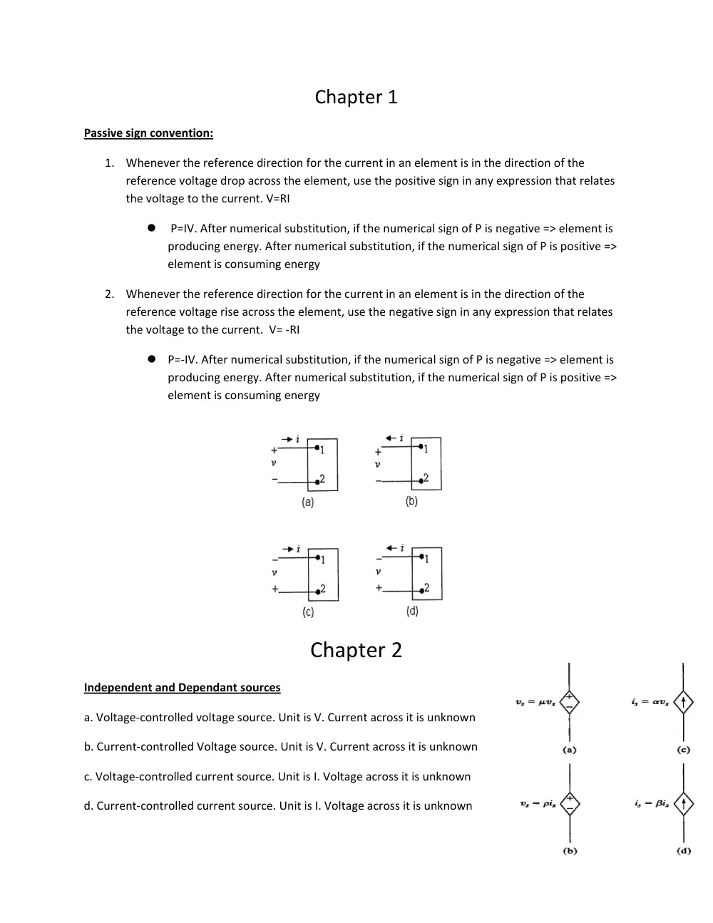
Passive sign convention:
1. Whenever the reference direction for the current in an element is in the direction of the
reference voltage drop across the element, use the positive sign in any expression that relates
the voltage to the current. V=RI
� P=IV. After numerical substitution, if the numerical sign of P is negative => element is
producing energy. After numerical substitution, if the numerical sign of P is positive =>
element is consuming energy
2. Whenever the reference direction for the current in an element is in the direction of the
reference voltage rise across the element, use the negative sign in any expression that relates
the voltage to the current. V= ‐RI
� P=‐IV. After numerical substitution, if the numerical sign of P is negative => element is
producing energy. After numerical substitution, if the numerical sign of P is positive =>
element is consuming energy
Chapter 2
Independent and Dependant sources
a. Voltage‐controlled voltage source. Unit is V. Current across it is unknown
b. Current‐controlled Voltage source. Unit is V. Current across it is unknown
c. Voltage‐controlled current source. Unit is I. Voltage across it is unknown
d. Current‐controlled current source. Unit is I. Voltage across it is unknown
N
iA
iC
iB
iD
v1
v5
v2
v4
v3
q
+
+
+
+
+
–
–
–
–
–
+
Circuit Terminologies:
•
An essential node is the junction of three or more circuit elements.
•
An essential branch is a branch that connects two essential nodes without passing through an
essential node.
•
A mesh is a loop that does not enclose any other loop.
KCL:
KCL may be stated as follows: at any instant of time, the sum of currents entering a
node is equal to the sum of currents leaving the node. At node N, for example, KCL
gives: iA + iB = iC + iD. Alternatively, iA + iB – iC – iD = 0, where currents flowing towards a
node have been arbitrarily assigned a positive sign, which means that currents flowing
away from a node should be assigned a negative sign.
KVL:
KVL may be stated as follows: At any instant of time, the sum of the voltage rises
around any loop is equal to the sum of the voltage drops around the loop. An
equivalent statement of KVL is: At any instant of time, the algebraic sum of the
voltages around any loop is zero, since voltage drops and voltage rises are assigned
opposite signs
Chapter 3
•
In a series connection of resistors, the same current flows through all the resistors, and voltages
across the individual resistors may be added algebraically to obtain the total voltage across the
series combination
•
In a parallel connection of resistors, the same voltage exists across all the resistors, and the
currents through the individual resistors may be added algebraically to obtain the total current
Voltage divider
•
If a load RL is connected across R2, then
)
||
(
)
||
(
2
1
2
L
L
SRC
L
R
R
R
R
R
v
v
+
=
vSRC
R1
+
+
v1
R2
RL
iL
vL
–
+
–
+
–
–
R1
R2
vSRC
–
+
–
+
i1
i2
i
R1
R2
R3
Rx
a
b
c
d
VSRC
–
+
A
I = 0
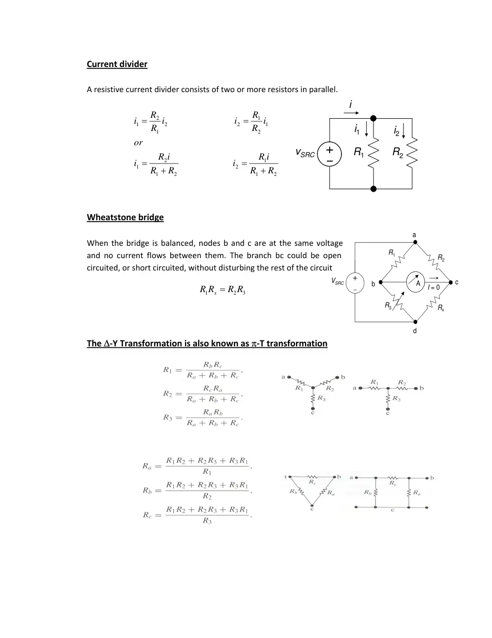
Current divider
A resistive current divider consists of two or more resistors in parallel.
Wheatstone bridge
When the bridge is balanced, nodes b and c are at the same voltage
and no current flows between them. The branch bc could be open
circuited, or short circuited, without disturbing the rest of the circuit
The Δ‐Y Transformation is also known as π‐T transformation
2
1
1
2
2
1
2
1
1
2
1
2
2
1
2
1
R
R
R i
i
R
R
R i
i
or
R i
R
i
R i
R
i
+
=
+
=
=
=
3
2
1
R R
R R
x =
VSRC
RSRC
R5
I1
I3
R1
R3
R4
R2
I2
a
b
c
d
–
+
Chapter 4
Number of equations to solve for independent sources only = number of essential nodes‐1
Number of equations to solve for independent sources + dependant sources = number of essential
nodes‐1+ equation relating the dependant variables of the source to the other circuit variables
Mesh‐Current Method
Equations based on KVL are then written for each mesh directly in terms of the V‐I relations
Number of equations to solve for independent sources only = number of meshes
Number of equations to solve for independent sources + dependant sources = number of meshes +
equation relating the dependant variables of the source to the other circuit variables
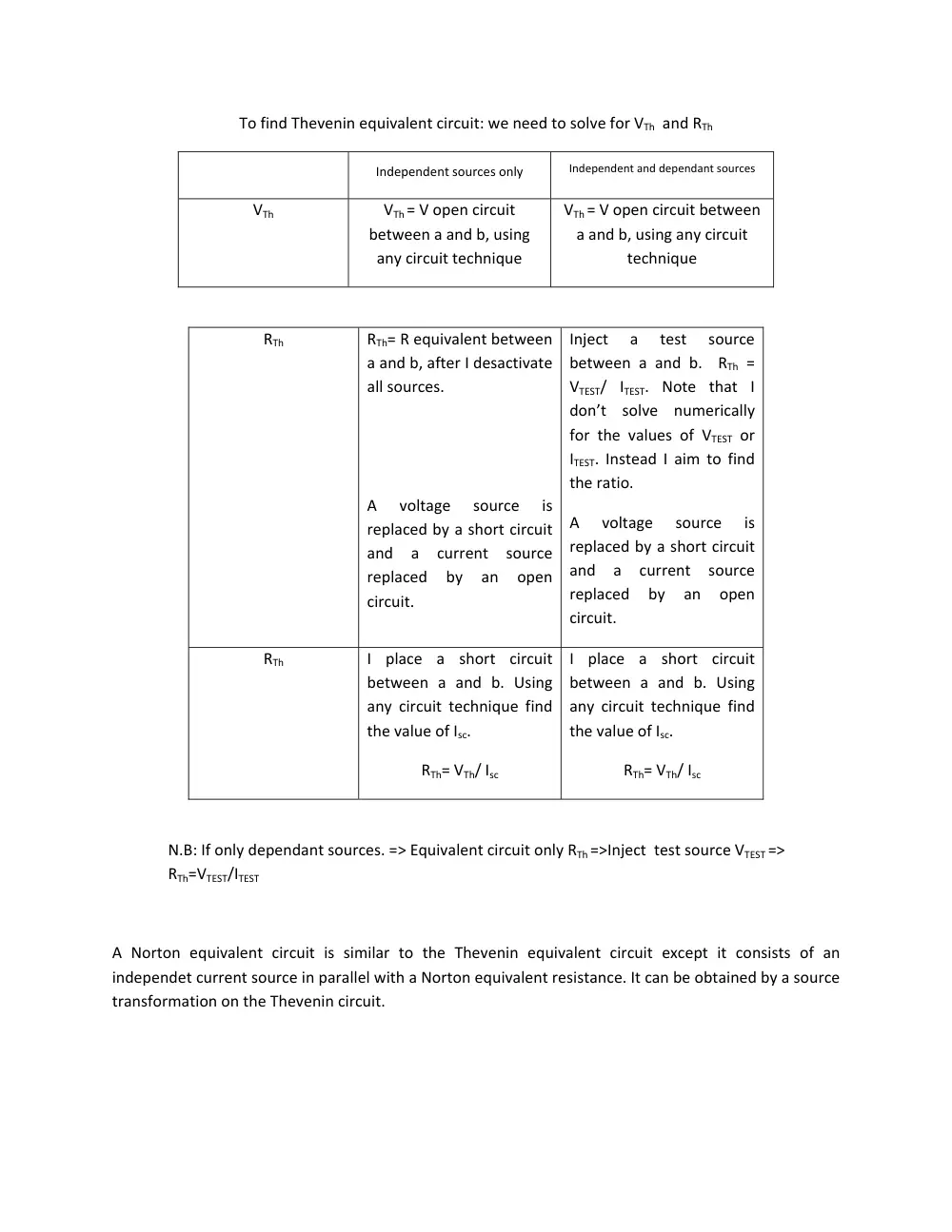
To find Thevenin equivalent circuit: we need to solve for VTh and RTh
Independent sources only
Independent and dependant sources
VTh
VTh = V open circuit
between a and b, using
any circuit technique
VTh = V open circuit between
a and b, using any circuit
technique
RTh
RTh= R equivalent between
a and b, after I desactivate
all sources.
A
voltage
source
is
replaced by a short circuit
and
a
current
source
replaced
by
an
open
circuit.
Inject
a
test
source
between a and b. RTh =
VTEST/ ITEST. Note that I
don’t solve numerically
for the values of VTEST or
ITEST. Instead I aim to find
the ratio.
A
voltage
source
is
replaced by a short circuit
and
a
current
source
replaced
by
an
open
circuit.
RTh
I place a short circuit
between a and b. Using
any circuit technique find
the value of Isc.
RTh= VTh/ Isc
I place a short circuit
between a and b. Using
any circuit technique find
the value of Isc.
RTh= VTh/ Isc
N.B: If only dependant sources. => Equivalent circuit only RTh =>Inject test source VTEST =>
RTh=VTEST/ITEST
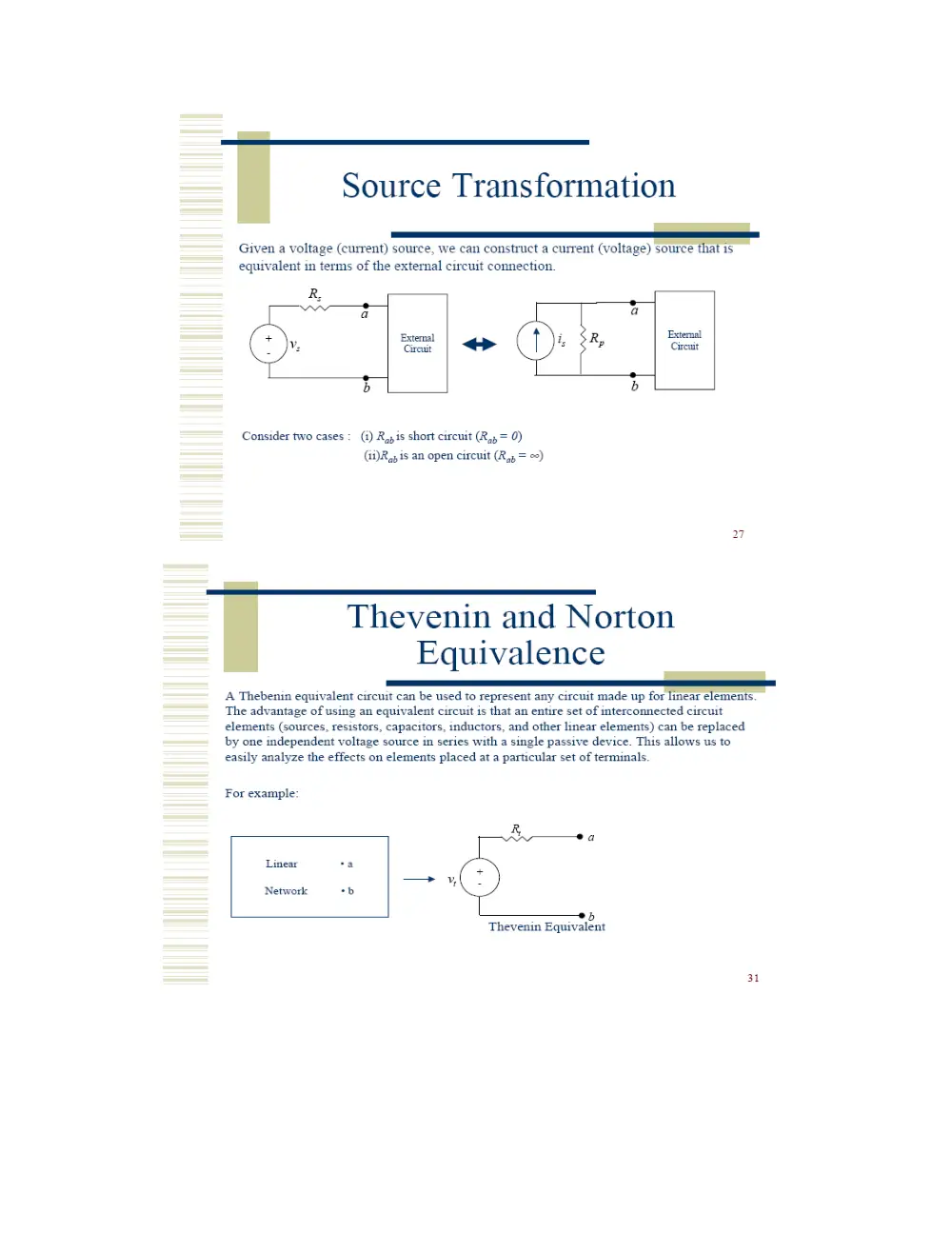
A Norton equivalent circuit is similar to the Thevenin equivalent circuit except it consists of an
independet current source in parallel with a Norton equivalent resistance. It can be obtained by a source
transformation on the Thevenin circuit.
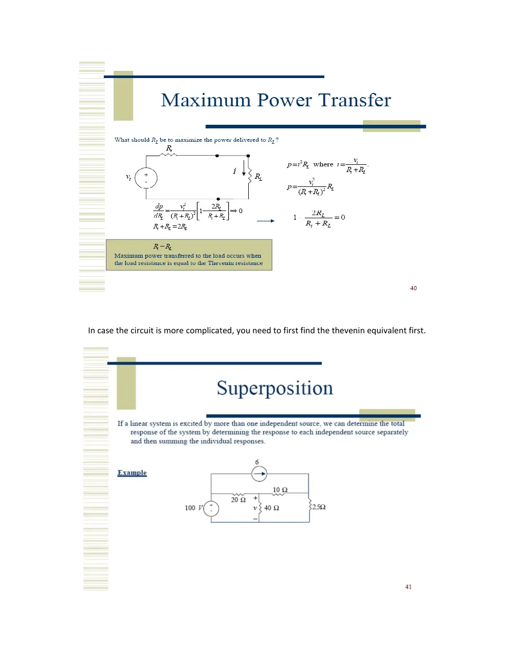
In case the circuit is more complicated, you need to first find the thevenin equivalent first.
Chapter 5
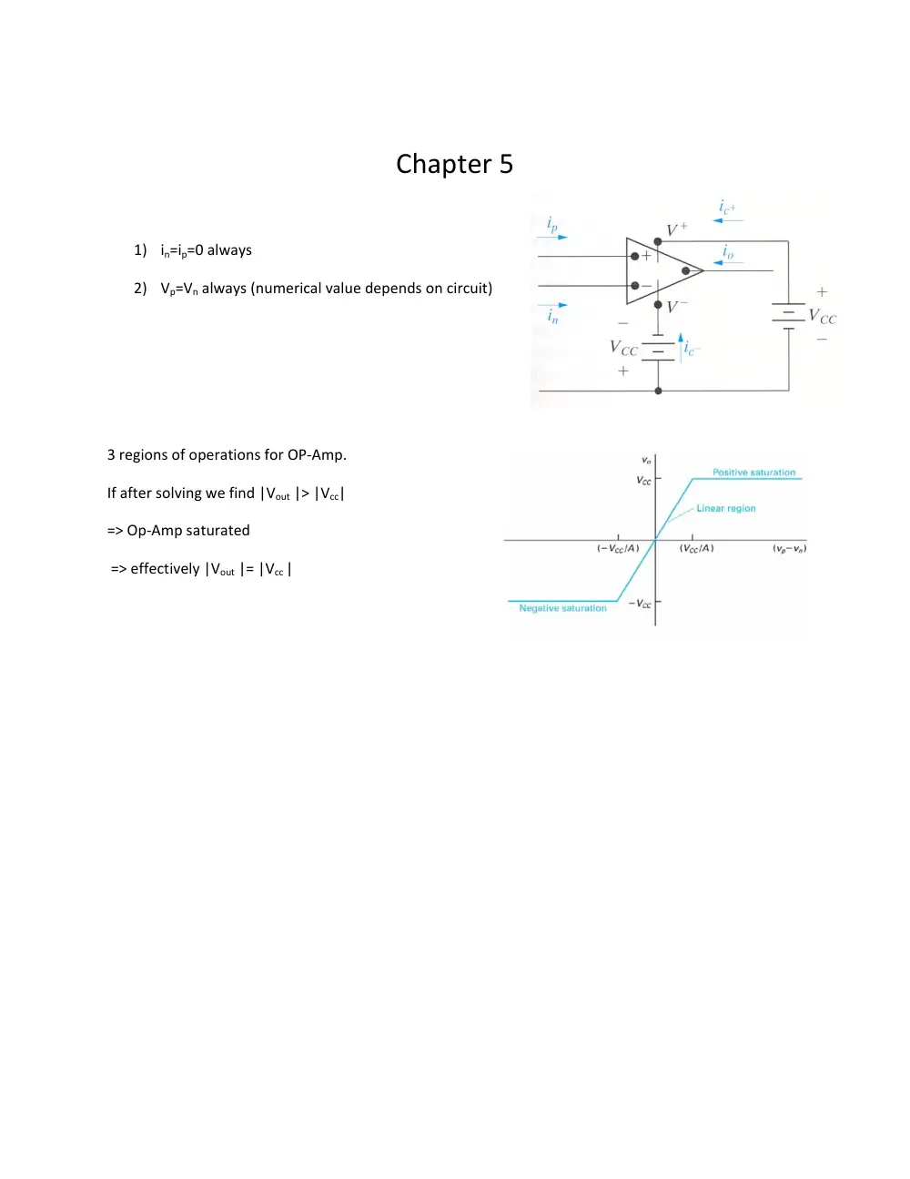
1) in=ip=0 always
2) Vp=Vn always (numerical value depends on circuit)
3 regions of operations for OP‐Amp.
If after solving we find |Vout |> |Vcc|
=> Op‐Amp saturated
=> effectively |Vout |= |Vcc |