
EECE 210 Syllabus, Fall 2011
American University of Beirut · Electric Circuits · 3 pages


More EECE 210 files
Show the text of this lab
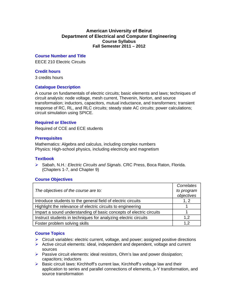
American University of Beirut
Department of Electrical and Computer Engineering
Course Syllabus
Fall Semester 2011 – 2012
Course Number and Title
EECE 210 Electric Circuits
Credit hours
3 credits hours
Catalogue Description
A course on fundamentals of electric circuits; basic elements and laws; techniques of
circuit analysis: node voltage, mesh current, Thevenin, Norton, and source
transformation; inductors, capacitors, mutual inductance, and transformers; transient
response of RC, RL, and RLC circuits; steady state AC circuits; power calculations;
circuit simulation using SPICE.
Required or Elective
Required of CCE and ECE students
Prerequisites
Mathematics: Algebra and calculus, including complex numbers
Physics: High-school physics, including electricity and magnetism
Textbook
Sabah, N.H.: Electric Circuits and Signals. CRC Press, Boca Raton, Florida.
(Chapters 1-7, and Chapter 9)
Course Objectives
The objectives of the course are to:
Correlates
to program
objectives
Introduce students to the general field of electric circuits
1, 2
Highlight the relevance of electric circuits to engineering
1
Impart a sound understanding of basic concepts of electric circuits
1
Instruct students in techniques for analyzing electric circuits
1,2
Foster problem solving skills
1,2
Course Topics
Circuit variables: electric current, voltage, and power; assigned positive directions
Active circuit elements: ideal, independent and dependent, voltage and current
sources
Passive circuit elements: ideal resistors, Ohm’s law and power dissipation;
capacitors; inductors
Basic circuit laws: Kirchhoff’s current law, Kirchhoff’s voltage law and their
application to series and parallel connections of elements, -Y transformation, and
source transformation
Basic analysis of resistive circuits: node-voltage and mesh-current methods;
superposition
Circuit simplification techniques: Thevenin’s and Norton’s equivalent circuits;
substitution theorem; source rearrangement; removal of redundant elements
Sinusoidal steady-state: response to complex excitation; phasors and phasor
relations of circuit elements; impedance and reactance; circuit representation in the
frequency domain; phasor diagrams
Mutual inductance, linear and ideal transformers; reflection of circuits; transformer
imperfections
Power relations: instantaneous and average power, complex power, power factor
correction, maximum power transfer
Measurement of current, voltage and power; effect of finite resistance of measuring
instruments
Responses to periodic inputs: Fourier series; symmetry properties; circuit responses
to periodic inputs; average power and rms values
Course Learning Outcomes
At the end of the course, students should be able to:
Correlates to program
outcomes*
H
M
L
Understand the concepts of current, voltage, power,
and energy and their interrelations
A
Understand the basic attributes of voltage sources,
current sources, resistors, capacitors, inductors and
their voltage-current relations
a, e
Apply KCL and KVL to basic analysis of electric
circuits
K
Analyze resistive circuits by the node-voltage
method, mesh-current method, or superposition
K
e
Derive TEC and NEC between specified terminals of
an electric circuit
K
e
Simplify a circuit by using the substitution and source
absorption theorems, or by rearranging sources, or
by removing redundant elements
K
e
Represent circuits in the frequency domain in terms
of phasors and impedances or admittances
K
e
m
Apply circuit relations and theorems in the frequency
domain in order derive steady-state sinusoidal
responses
K
e
Analyze circuits that include linear or ideal
transformers
K
e
a
Analyze power circuits in terms of real, reactive, and
complex power and apply these to power factor
correction
K
e, m
Apply the condition for maximum power transfer and
determine the maximum power transferred
K
h
Derive the Fourier series expansion of a periodic
function
K
m
a
Determine the response of a circuit to a periodic input
K
a
Simulate basic electric circuits using PSpice
K
a
* H: High correlation, M: Medium correlation, L: Low correlation
Resources
Textbook
PSpice
Moodle
Evaluation Methods
Final exam
40%
Quizzes (3)
48%
PSpice Quiz
12%
Professional Components
Engineering topics: 90%
General education: 0%
Mathematics and basic sciences: 10%
Person(s) who prepared this description and date of preparation
Karim Kabalan, Fadi Karameh and Nassir Sabah, Sept 2008
Date of last revision
Sep 2009