
EECE 312L Notes Experiment 3 Notes, Fall 2013
American University of Beirut · Circuits and Electronics Lab · 6 pages
More EECE 312L files
- Notes Experiment 2 Notes · Fall 2013NotesView
- Notes Experiment 4 Notes · Fall 2013NotesView
- Notes Experiment 11 Notes · Fall 2013NotesView
- Notes Experiment 7 Noes · Fall 2013NotesView
- Notes Experiment 5 Notes · Fall 2013NotesView
- Notes Experiment 6 Notes · Fall 2013NotesView
- Notes Experiment 10 Notes · Fall 2013NotesView
- Notes Experiment 1 Notes · Fall 2013NotesView
Show the text of this notes
Experiment 3
Voltage Dividers and Thévenin’s Theorem
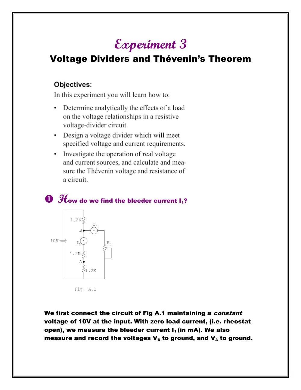
How do we find the bleeder current I1?
We first connect the circuit of Fig A.1 maintaining a constant
voltage of 10V at the input. With zero load current, (i.e. rheostat
open), we measure the bleeder current I1 (in mA). We also
measure and record the voltages VB to ground, and VA to ground.
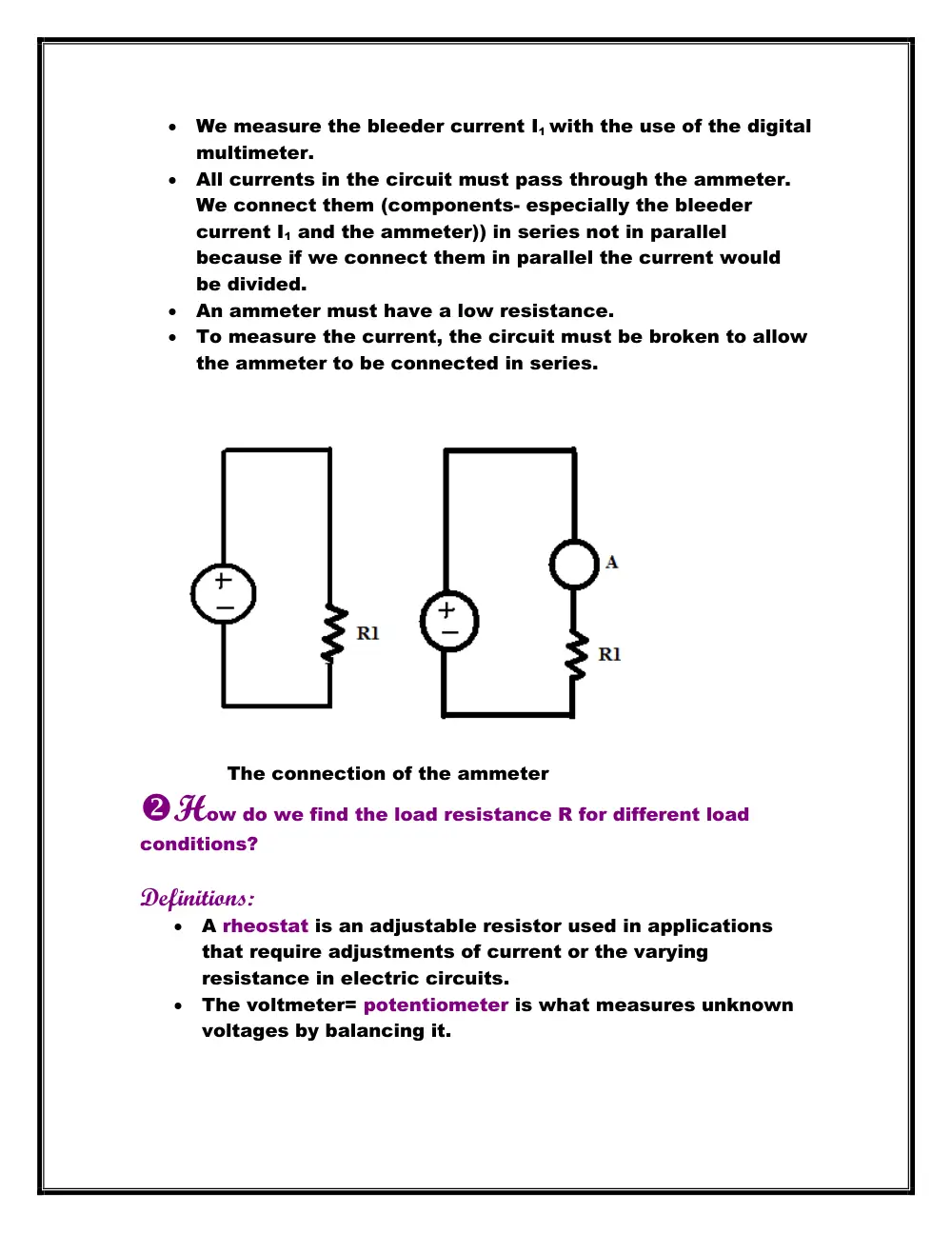
We measure the bleeder current I1 with the use of the digital
multimeter.
All currents in the circuit must pass through the ammeter.
We connect them (components- especially the bleeder
current I1 and the ammeter)) in series not in parallel
because if we connect them in parallel the current would
be divided.
An ammeter must have a low resistance.
To measure the current, the circuit must be broken to allow
the ammeter to be connected in series.
The connection of the ammeter
How do we find the load resistance R for different load
conditions?
Definitions:
A rheostat is an adjustable resistor used in applications
that require adjustments of current or the varying
resistance in electric circuits.
The voltmeter= potentiometer is what measures unknown
voltages by balancing it.
We connect the rheostat in the circuit and adjust it to draw 2 mA
by the digital multimeter of load current while maintaining
V=10V, measured. We measure and record the bleeder current
and the voltages VB and VA. We open the load resistor RL, with out
varying the setting of the arm. We measure and record the
resistance to which it was set to draw 2 mA of load current. We
reconnect RL after this measurement (by the digital multimeter).
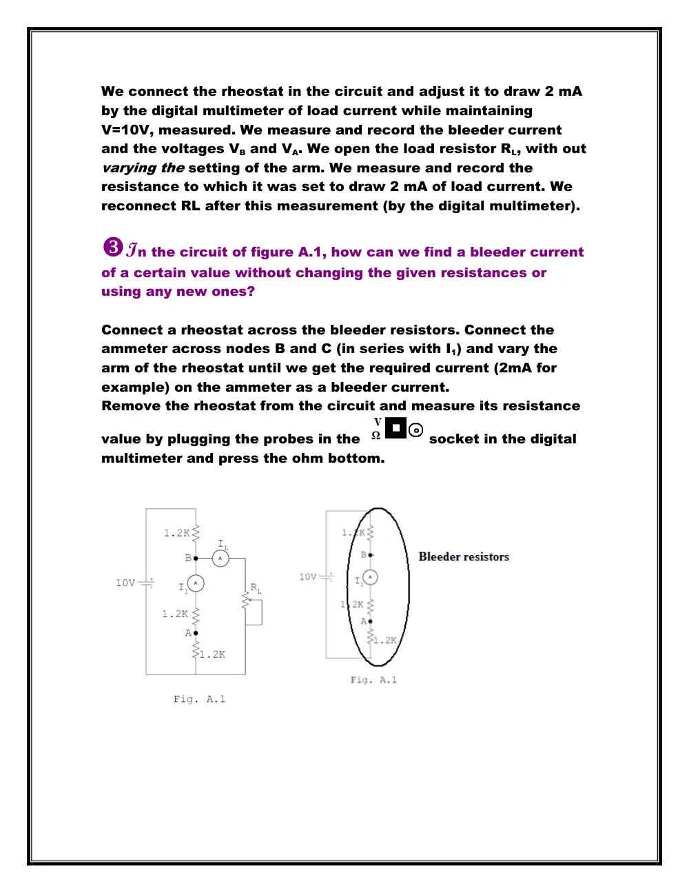
In the circuit of figure A.1, how can we find a bleeder current
of a certain value without changing the given resistances or
using any new ones?
Connect a rheostat across the bleeder resistors. Connect the
ammeter across nodes B and C (in series with I1) and vary the
arm of the rheostat until we get the required current (2mA for
example) on the ammeter as a bleeder current.
Remove the rheostat from the circuit and measure its resistance
value by plugging the probes in the
socket in the digital
multimeter and press the ohm bottom.
How do we get the required value of a certain resistor?
If we didn’t have the required design-value resistor, we adjust a
potentiometer connected as a rheostat to the desired value, or
make up the resistor from a combination (series, parallel) of the
other resistors. Or simply measure the value using a digital
multimeter (according to the current value).
How does the load current vary with the load resistance R?
Explain why.
The load current decreases as the load resistance increases.
This is a logical observation since current and resistance are
inversely proportional with respect to voltage (By Ohm's law).
What is the effect on bleeder current I1 as the load current
increases? Explain why.
As the load current increases, the bleeder current I1 decreases.
Even though the source current is not constant, we can see that
the general sense of linear relationship between the three
currents conserved: IS = I1 + IL.
What is the effect on the voltages VA and VB at the divider
taps as the load current increases? Explain why.
Both VA and VB decrease as the load current increases. This is
valid since these voltages are constant multiples of the bleeder
current and the bleeder current decreases with the increase in
load current.
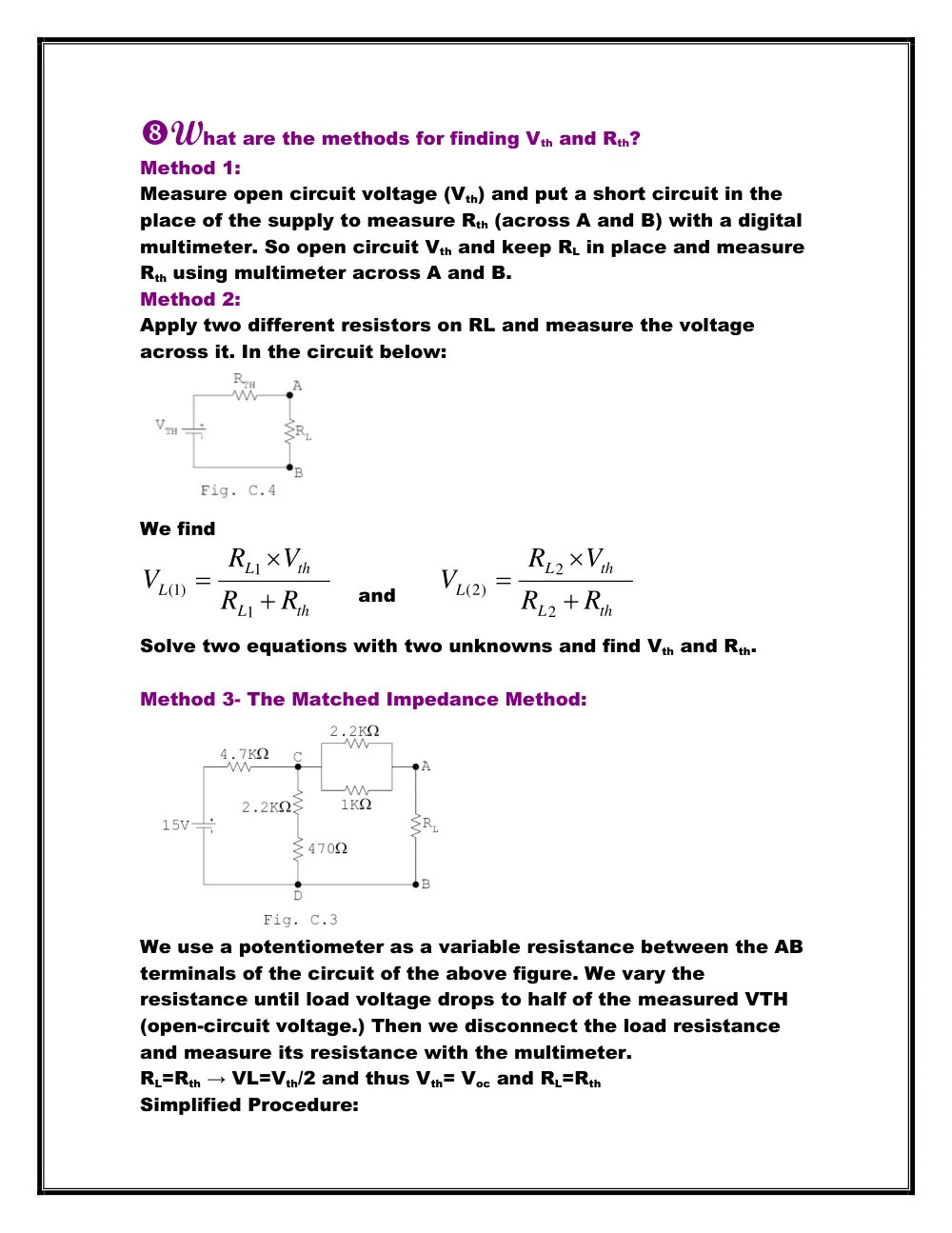
What are the methods for finding Vth and Rth?
Method 1:
Measure open circuit voltage (Vth) and put a short circuit in the
place of the supply to measure Rth (across A and B) with a digital
multimeter. So open circuit Vth and keep RL in place and measure
Rth using multimeter across A and B.
Method 2:
Apply two different resistors on RL and measure the voltage
across it. In the circuit below:
We find
th
L
th
L
L
R
R
V
R
V
1
1
1( )
and
th
L
th
L
L
R
R
V
R
V
2
2
(2)
Solve two equations with two unknowns and find Vth and Rth.
Method 3- The Matched Impedance Method:
We use a potentiometer as a variable resistance between the AB
terminals of the circuit of the above figure. We vary the
resistance until load voltage drops to half of the measured VTH
(open-circuit voltage.) Then we disconnect the load resistance
and measure its resistance with the multimeter.
RL=Rth → VL=Vth/2 and thus Vth= Voc and RL=Rth
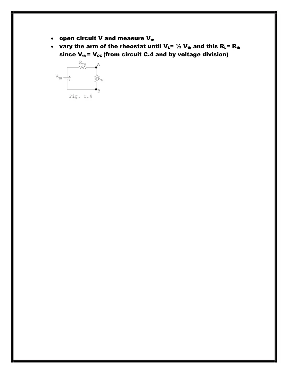
Simplified Procedure:
open circuit V and measure Vth
vary the arm of the rheostat until VL= ½ Vth and this RL= Rth
since Vth = VOC (from circuit C.4 and by voltage division)