
EECE 312L Notes Experiment 5 Notes, Fall 2013
American University of Beirut · Circuits and Electronics Lab · 9 pages


More EECE 312L files
- Notes Experiment 2 Notes · Fall 2013NotesView
- Notes Experiment 3 Notes · Fall 2013NotesView
- Notes Experiment 11 Notes · Fall 2013NotesView
- Notes Experiment 7 Noes · Fall 2013NotesView
- Notes Experiment 4 Notes · Fall 2013NotesView
- Notes Experiment 6 Notes · Fall 2013NotesView
- Notes Experiment 10 Notes · Fall 2013NotesView
- Notes Experiment 1 Notes · Fall 2013NotesView
Show the text of this notes
Experiment 5
Diode Rectifier Circuits
Define a rectifier.
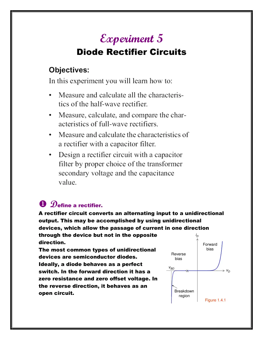
A rectifier circuit converts an alternating input to a unidirectional
output. This may be accomplished by using unidirectional
devices, which allow the passage of current in one direction
through the device but not in the opposite
direction.
The most common types of unidirectional
devices are semiconductor diodes.
Ideally, a diode behaves as a perfect
switch. In the forward direction it has a
zero resistance and zero offset voltage. In
the reverse direction, it behaves as an
open circuit.
Figure 1.4.1
vD
iD
Forward
bias
Reverse
bias
Breakdown
region
vBD
The half-wave rectifier blocks the negative variations of the
input; the output is approximately equal to the input when the
input is positive, and is zero otherwise. In the full-wave rectifier,
on the other hand, the output is approximately equal to the
absolute value of the input.
What are the important characteristics of the rectifier?
The most important characteristics which must be specified for a
rectifier circuit are:
1. DC output voltage.
The DC output voltage VDC is: (from the highest to the lowest)
center-tapped full- wave rectifier, bridge full-wave rectifier (the
output is always approximately equal to the absolute value of
the input), and then half-wave rectifier (DC output is zero half
of the time). The full wave-rectifiers have a greater DC output
voltage than the half-wave rectifier.
2. ripple-factor, defined as a ratio of the peak-to-peak ripple
(voltage variation in the output) to the average voltage across
the load.
The three circuits have approximately the same ripple peak-to-peak
voltage. However, the bridge rectifier has a ripple peak-to-peak
voltage Vpp slightly less due to the two diodes that are conducting at
any time.
3. Average and peak currents in each diode.
The average and peak currents in the rectifiers are the greatest in
the half-wave rectifier, and they are approximately equal in both
full-wave rectifiers since power used is relatively the same
amount at the output resistance which is approximately = P=
V2rms2 / R.
4. Peak inverse voltage (PIV) for each diode.
The descending order is by the value of the PIV is: center-tapped
full- wave rectifier, half-wave rectifier where the PIV equals the
peak input voltage; bridge rectifier (equals half that of the
center-tap full- wave).
5. Percent regulation, defined as (VL – Vo / Vo) x 100, where V0 is
the no-load voltage and VL is the full-load voltage.
The percent regulation could be represented in the following
descending order: the bridge full-wave rectifier, the half-wave
rectifier and the center-tapped full-wave rectifier.
6. Transformer requirements, such as the secondary winding
voltage and current ratings.
According to the current ratings, we have seen that the half-wave
rectifier requires the greatest secondary current while the other two
require only half of that value. Therefore, the magnetic
polarization is strongest in the half-wave rectifier and the center-
tap rectifier.
Notes:
It should be carefully noted that these characteristics, depend, in
general, upon the type of load connected to the rectifier output,
i.e., whether it is resistive, capacitive or inductive.
A transformer is used for stepping-down the input AC voltage. It
is a device that transmits AC power from one circuit to another
through magnetic coupling, often with no conductive connection.
The transformation process obeys the relationships: and, where
subscripts 1 and 2 refer to the primary and secondary sides,
respectively.
A capacitor can be connected in parallel at the output of the
rectifier to smooth the voltage variations. An approximate
analysis for a full-wave rectifier with a capacitor filter gives the
following:
Where V2max is the peak AC input voltage (at the secondary of the
transformer), RL is the load resistance, C is the filter
capacitance, and f is the frequency of the AC voltage.
Definition: rectifier circuit converts an alternating, or
bidirectional, current or voltage to a unidirectional one.
Half- Wave Rectifier:
iL
vL
RL
Vmsint
VD0
rD
(a)
_
+
_
+
vL
Vm
t
Figure 1.3.1
(b)
-
VD0
Vmsint
2
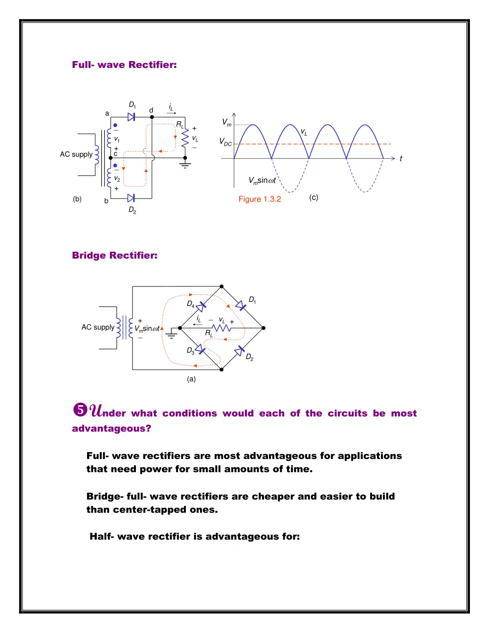
Full- wave Rectifier:
Bridge Rectifier:
Under what conditions would each of the circuits be most
advantageous?
Full- wave rectifiers are most advantageous for applications
that need power for small amounts of time.
Bridge- full- wave rectifiers are cheaper and easier to build
than center-tapped ones.
Half- wave rectifier is advantageous for:
vL
v1
v2
D1
D2
RL
c
a
b
d
iL
(b)
AC supply
_
+
_
+
_
+
VDC
Vm
vL
t
Figure 1.3.2
(c)
Vmsint
D4
D1
D2
D3
vL
RL
(a)
AC supply
Vmsint
_
+
+
_
iL
Applications such as charging a battery because this
operation takes more time (twice the time of a full-wave
rectifier.
Simplicity and cheap cost.
Note:
For each of the circuits in Figs 1, 2, and 3 we adjust the load
resistor to get IDC = 50 mA and we observe the output across the
load on the oscilloscope.
How do we find the different quantities mentioned in the
Theory section?
VDC: DC output voltage measured by the mean value on the
oscilloscope screen
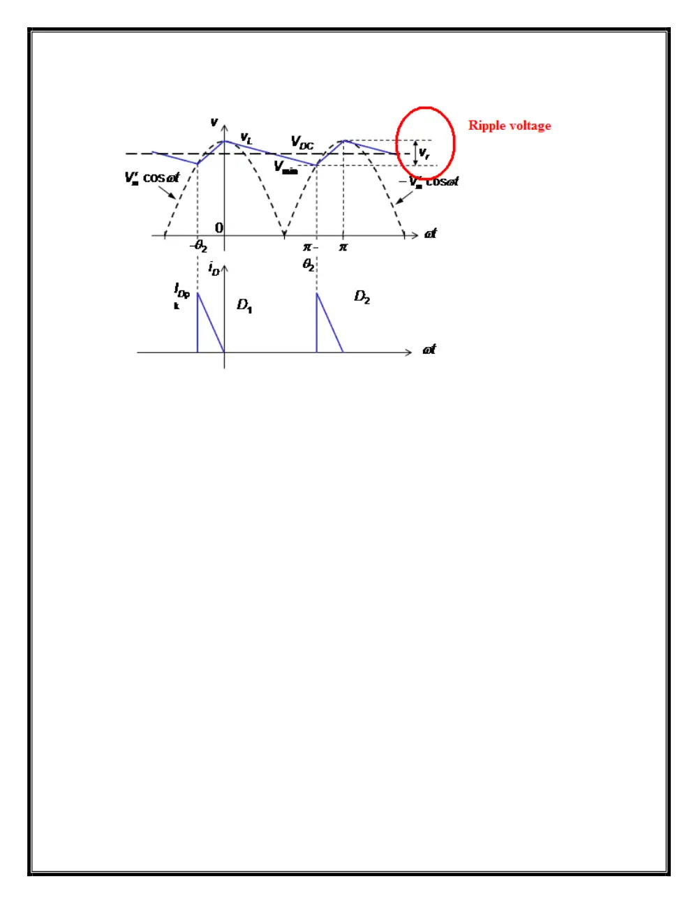
V ripple: peak to peak value on the oscilloscope screen
IDC= 50 mA (given) determined by the digital multimeter
I peak= V peak/R (R found by adjusting the rheostat)
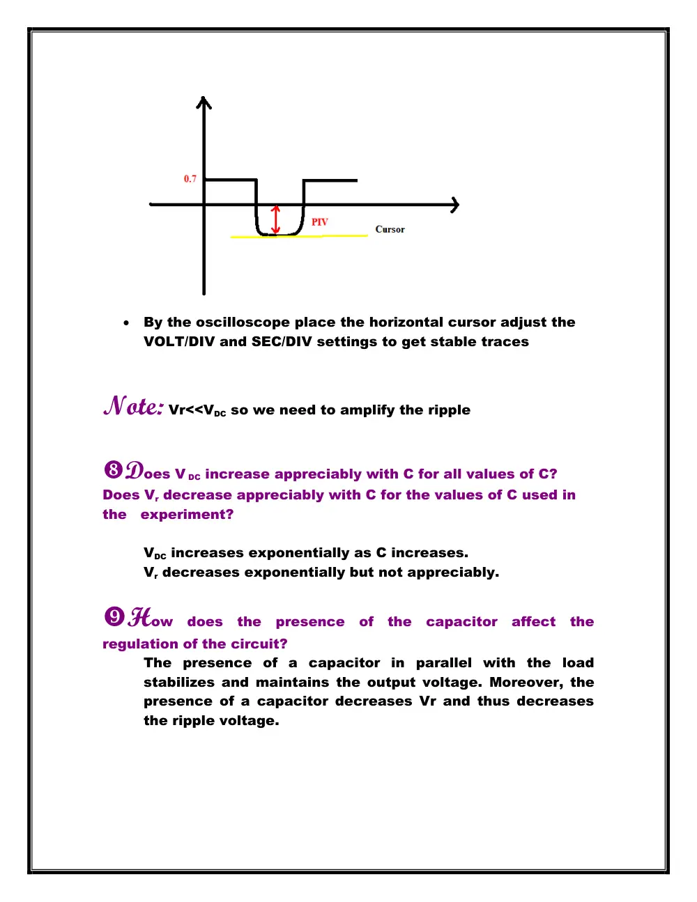
PIV: peak inverse voltage. It could be calculated by the
oscilloscope across the diode
By the oscilloscope place the horizontal cursor adjust the
VOLT/DIV and SEC/DIV settings to get stable traces
Note: Vr<<VDC so we need to amplify the ripple
Does V DC increase appreciably with C for all values of C?
Does Vr decrease appreciably with C for the values of C used in
the experiment?
VDC increases exponentially as C increases.
Vr decreases exponentially but not appreciably.
How does the presence of the capacitor affect the
regulation of the circuit?
The presence of a capacitor in parallel with the load
stabilizes and maintains the output voltage. Moreover, the
presence of a capacitor decreases Vr and thus decreases
the ripple voltage.
How do we measure the DC open circuit voltage?
Remove the resistor
Measure the mean value across the output by the
oscilloscope
JOUJOU
For certain required ripple voltage and DC voltage/current at the
load:
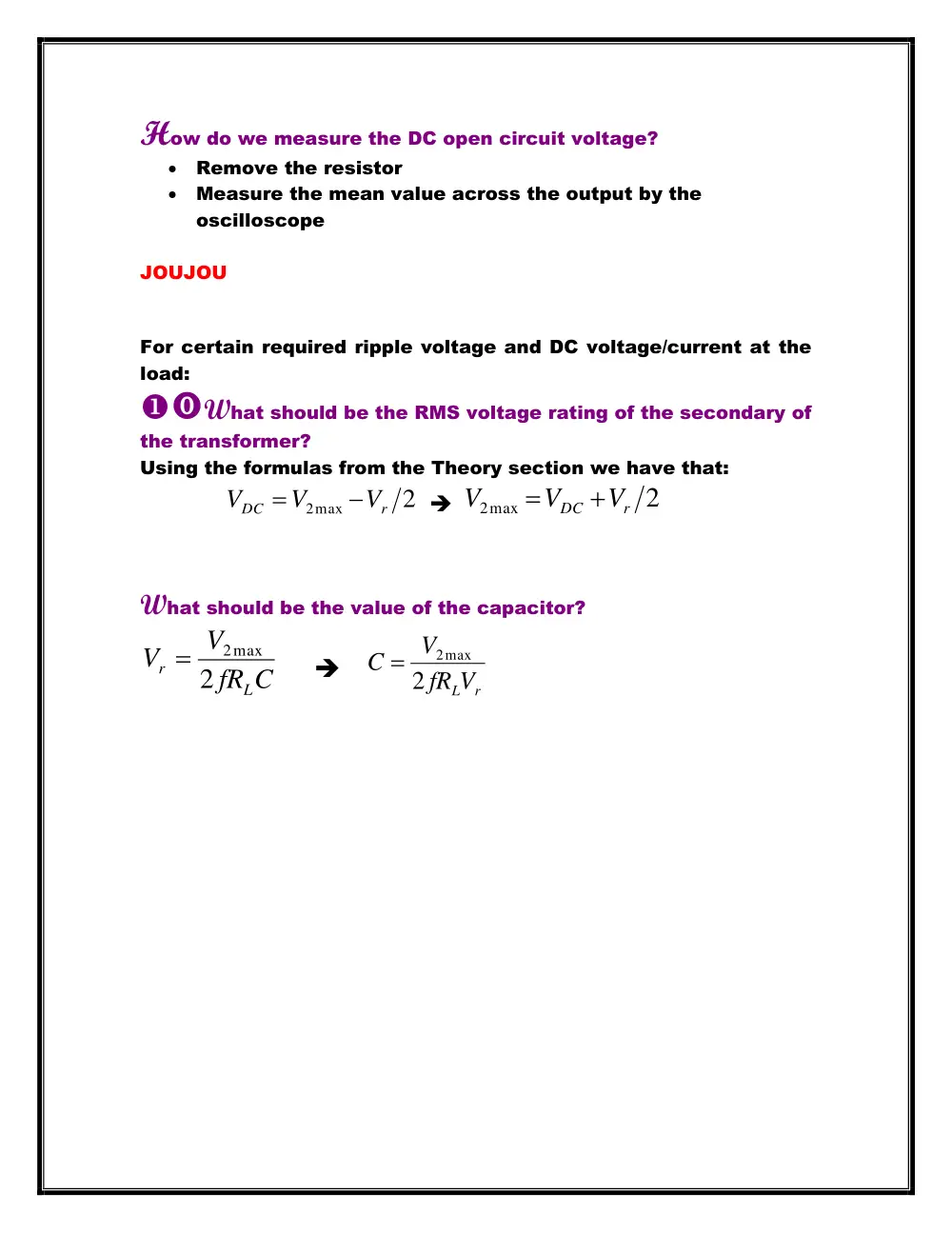
What should be the RMS voltage rating of the secondary of
the transformer?
Using the formulas from the Theory section we have that:
2
2max
r
DC
V
V
V
2
2max
r
DC
V
V
V
What should be the value of the capacitor?
fR C
V
V
L
r
2
2max
fRLVr
V
C
2
2max