
EECE 312L Notes Experiment 6 Notes, Fall 2013
American University of Beirut · Circuits and Electronics Lab · 7 pages


More EECE 312L files
- Notes Experiment 2 Notes · Fall 2013NotesView
- Notes Experiment 3 Notes · Fall 2013NotesView
- Notes Experiment 11 Notes · Fall 2013NotesView
- Notes Experiment 7 Noes · Fall 2013NotesView
- Notes Experiment 4 Notes · Fall 2013NotesView
- Notes Experiment 5 Notes · Fall 2013NotesView
- Notes Experiment 10 Notes · Fall 2013NotesView
- Notes Experiment 1 Notes · Fall 2013NotesView
Show the text of this notes
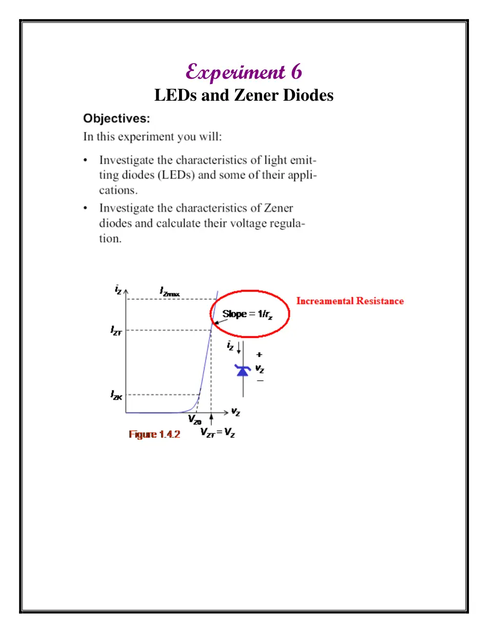
Experiment 6
LEDs and Zener Diodes
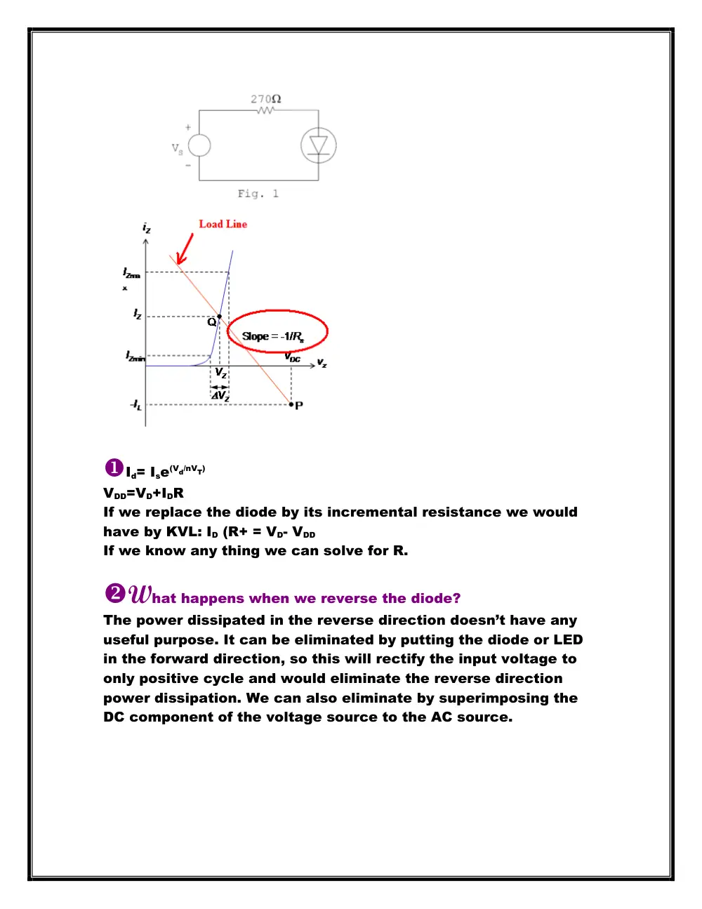
Id= Ise(Vd/nVT)
VDD=VD+IDR
If we replace the diode by its incremental resistance we would
have by KVL: ID (R+ = VD- VDD
If we know any thing we can solve for R.
What happens when we reverse the diode?
The power dissipated in the reverse direction doesn’t have any
useful purpose. It can be eliminated by putting the diode or LED
in the forward direction, so this will rectify the input voltage to
only positive cycle and would eliminate the reverse direction
power dissipation. We can also eliminate by superimposing the
DC component of the voltage source to the AC source.
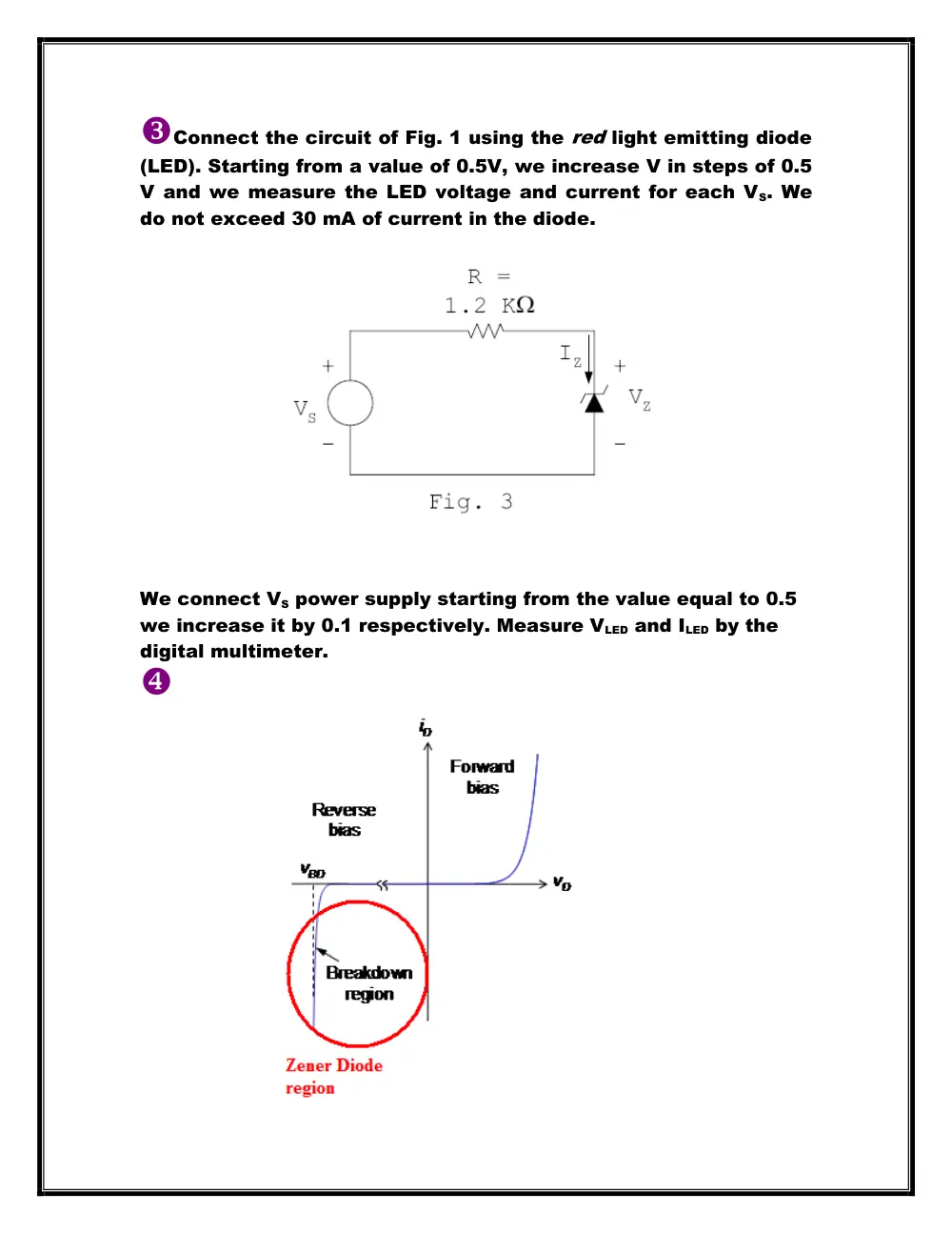
Connect the circuit of Fig. 1 using the red light emitting diode
(LED). Starting from a value of 0.5V, we increase V in steps of 0.5
V and we measure the LED voltage and current for each VS. We
do not exceed 30 mA of current in the diode.
We connect VS power supply starting from the value equal to 0.5
we increase it by 0.1 respectively. Measure VLED and ILED by the
digital multimeter.
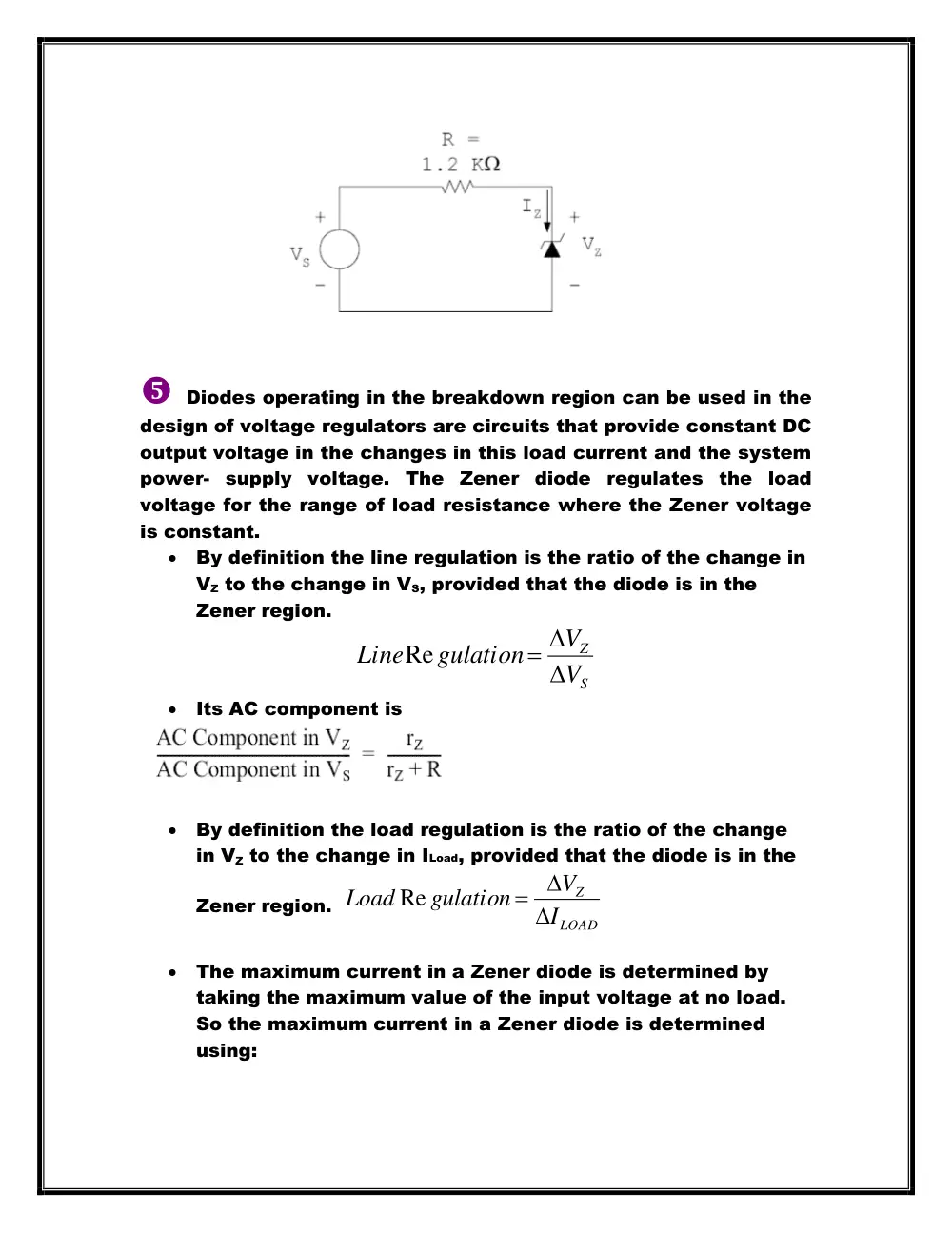
Diodes operating in the breakdown region can be used in the
design of voltage regulators are circuits that provide constant DC
output voltage in the changes in this load current and the system
power- supply voltage. The Zener diode regulates the load
voltage for the range of load resistance where the Zener voltage
is constant.
By definition the line regulation is the ratio of the change in
VZ to the change in VS, provided that the diode is in the
Zener region.
S
Z
V
V
gulation
Line
Re
Its AC component is
By definition the load regulation is the ratio of the change
in VZ to the change in ILoad, provided that the diode is in the
Zener region.
LOAD
Z
I
V
gulation
Load
Re
The maximum current in a Zener diode is determined by
taking the maximum value of the input voltage at no load.
So the maximum current in a Zener diode is determined
using:
Z
Z
R
P
I
max
max
The minimum current in the Zener diode is determined by
taking the minimum value of the input voltage with a very
small resistance connected to the load. Therefore, the
current in the load is at its maximum value thus the
minimum Zener current in the diode can be calculated by
the equation:
Iz min = I total – I loadmax
Thus, operating in the region close to the knee region allows us
to determine the minimum value of the Zener current.
Show that for a Zener voltage regulator, the value of the
resistor R should be chosen using the equation:
For the Zener diode to conduct VZK, IZK, and VS must be at a
certain minimum value. Thus, the load current is at its maximum
value. From the Zener voltage regulator circuit we get:
VS = RIS + VL
VS = R (IZK + IL) + (VZK + rZ IZK)
Due to the above discussed minimum current limit for the Zener
diode we replace VS by its minimum value and IL by its maximum
value and solving for R we obtain the equation:
We connect the circuit and measure VZ when VS is 15 V by a
digital multimeter.
Reduce the value of VS in steps of 0.5 V, and measure V Z
and I Z
VZ is measured by the digital multimeter. To measure the IZ we
remove on leg of the resistor and place it somewhere else.
Measure IZ by the multimeter placed across the two legs of the
resistor.
Measure VZ. What is the DC (average) value of VZ? What is the AC
component in VZ?
By the function generator:
Press on the offset bottom
Put all the other factors (amplitude…)
DC Vz value is measured by the mean value on the oscilloscope.
AC Vz values is the ripple value .We measure it by placing
the horizontal axis and adjust the VOLT/DIV and SEC/DIV
settings to get stable traces.
Joujou