
EECE 320 Final with Solutions, Fall 2009
American University of Beirut · Digital Systems Design · 10 pages · Prof. Mohammad Mansour · with solution

More EECE 320 files
- Final · Fall 2011Final examView
- Final · Fall 2010Final examView
- Problems For Final · Fall 2008Final examView
- Final · Fall 2005Final examView
- Final with Solution · Fall 2005Final exam · with solutionView
- Homework 2 and 3 · Summer 2016HomeworkView
- Homework 1 · Summer 2016HomeworkView
- Homework 1 · Fall 2016HomeworkView
Show the text of this final exam
L
=| Glo 161 01 OIN
00 01
qe D lip Flops, design a sequence detector that would output a Z=1 only after detecting
Se seqeeece TE oe i See inpet X. Call the states SO, S1 etc. (use don’t cares for illegal states and use
Ss Sar oor
B. Fill as much as needed in the corresponding state and transition tables shown below.
C. The excitation equations are given by: [3 points]
10
rn I
Dl= iS ne a
a at
al 2% 2g fe
D2=_Q@ } ee DE
(@) Q fo
Page 2 of 11
Lo x
Q1Q2Q3 0 1 Z
Mov [WSS ICs oe
Oe |SSe |ovne ©
AQV\Plo NV ION S| ©
| OVNI SSloo’s| &
Loeloed [Voi] ©
Yon [eeO[OVol] &
“esx | {Ds Ox
Q1Q2 Q1Q2
00 Of 11 #10 Q3x 00
Oo \ A © 00; <
P1eIATA 11, O
ole }|s]o 101 ©
D3
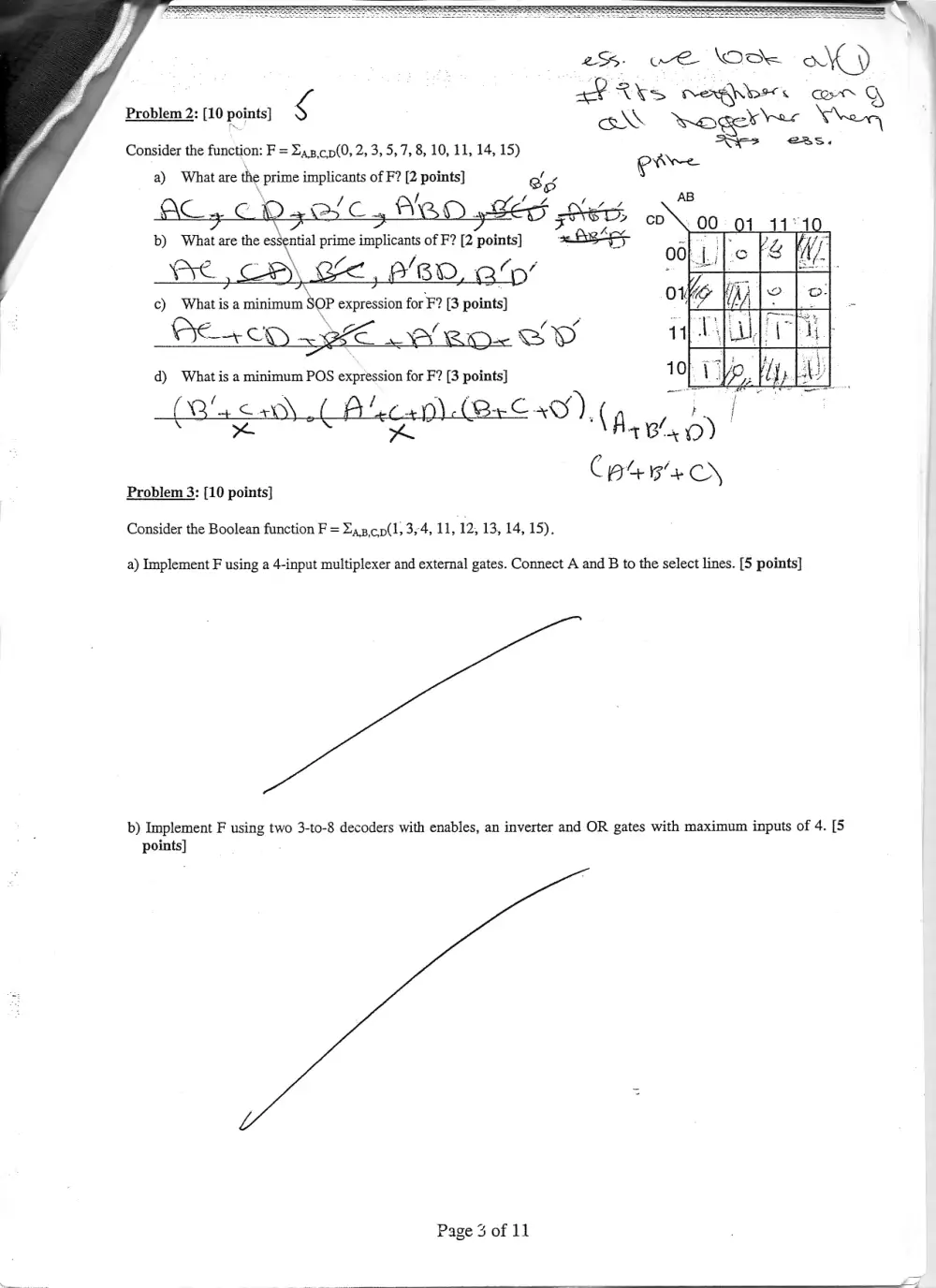
Problem 2: [10 points] g cad\ mogerres Veen
. . Ars «ea;
Consider the function: F = Z4z,cp(0, 2, 3, 5,7, 8, 10, 11, 14, 15)
a) What are the prime implicants of F? [2 points]
AB
AC CD sGC, BO EE Sie Ny
b) dee are the es prime <a of F? [2 points] 7. teh : : L Wr
OO} I. ; ‘ofS t/
AC, CB) of, 9/80, 3’ of baile Le]
c) Whatis a minimum n SOP Pegs for F? [3 points]
ReaD pee ee fall
d) What is a minimum POS expression for F? [3 points] 10} Le.
ack aco) ( Ai! 2G (On€ Cay), Ag y ts
* 1B x oD)
Cpe e+ >
Problem 3: [10 points]
Consider the Boolean function F = Zap.cp(1, 3,4, 11, 12, 13, 14, 15).
a) Implement F using a 4-input multiplexer and external gates. Connect A and B to the select lines. [5 points]
b) Implement F using two 3-to-8 decoders with enables, an inverter and OR gates with maximum inputs of 4. [5
points]
Page 3 of 11
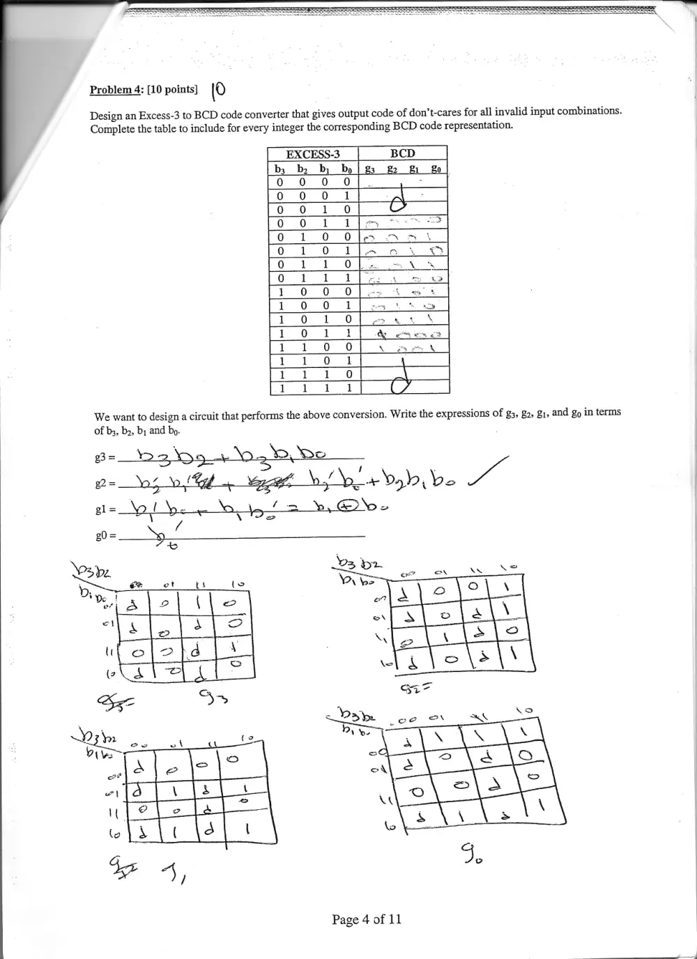
Problem 4: [10 points] [0
Design an Excess-3 to BCD code converter that gives output code of don’t-cares for all invalid input combinations.
Complete the table to include for every integer the corresponding BCD code representation.
EXCESS-3 BCD
b3__bz_ bi bo | 83 120
0 0 0 0 :
0 0 0 1 rat
0 oOo 1 0
0 021 1a oe
0 1.0 Of a mh
0 1 01a ne i eS
Oo 1 #1 £=+0 7 AK
0 1 1 14 e: ae)
1 0 0 0 ~ =<» *
1 0 0 1
1 0 1 +O
1 0 1 12
1 1 +O O
1 1 0 2
1 1 #1 +O
1 1 1 1
We want to design a circuit that performs the above conversion. Write the expressions of g3, 22, 21, and go in terms
of b3, bz, by and bo.
Page 4 of 11
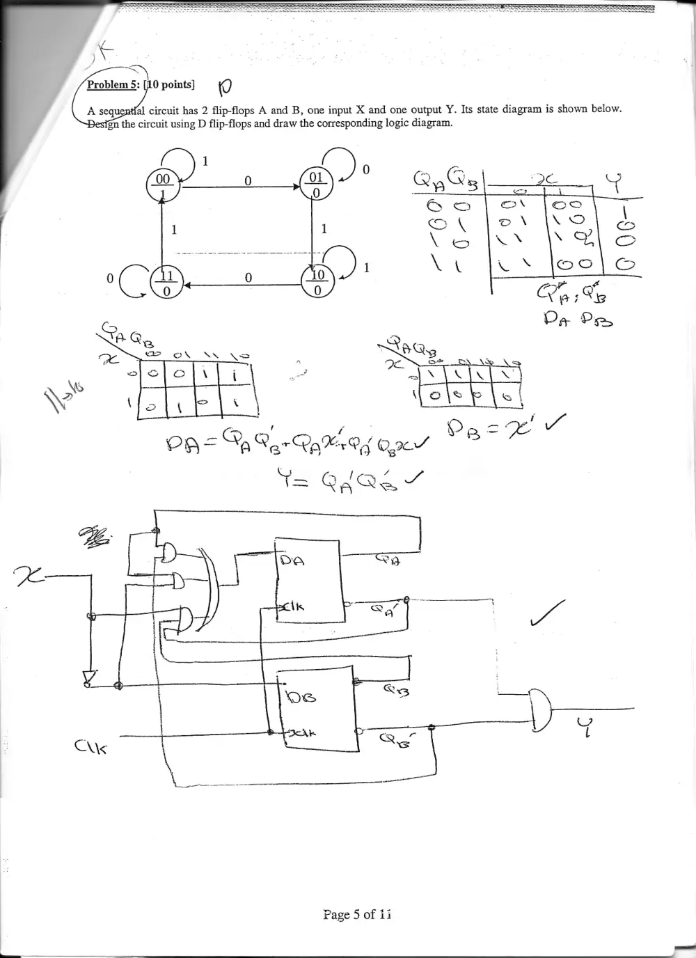
Page 5 of ii
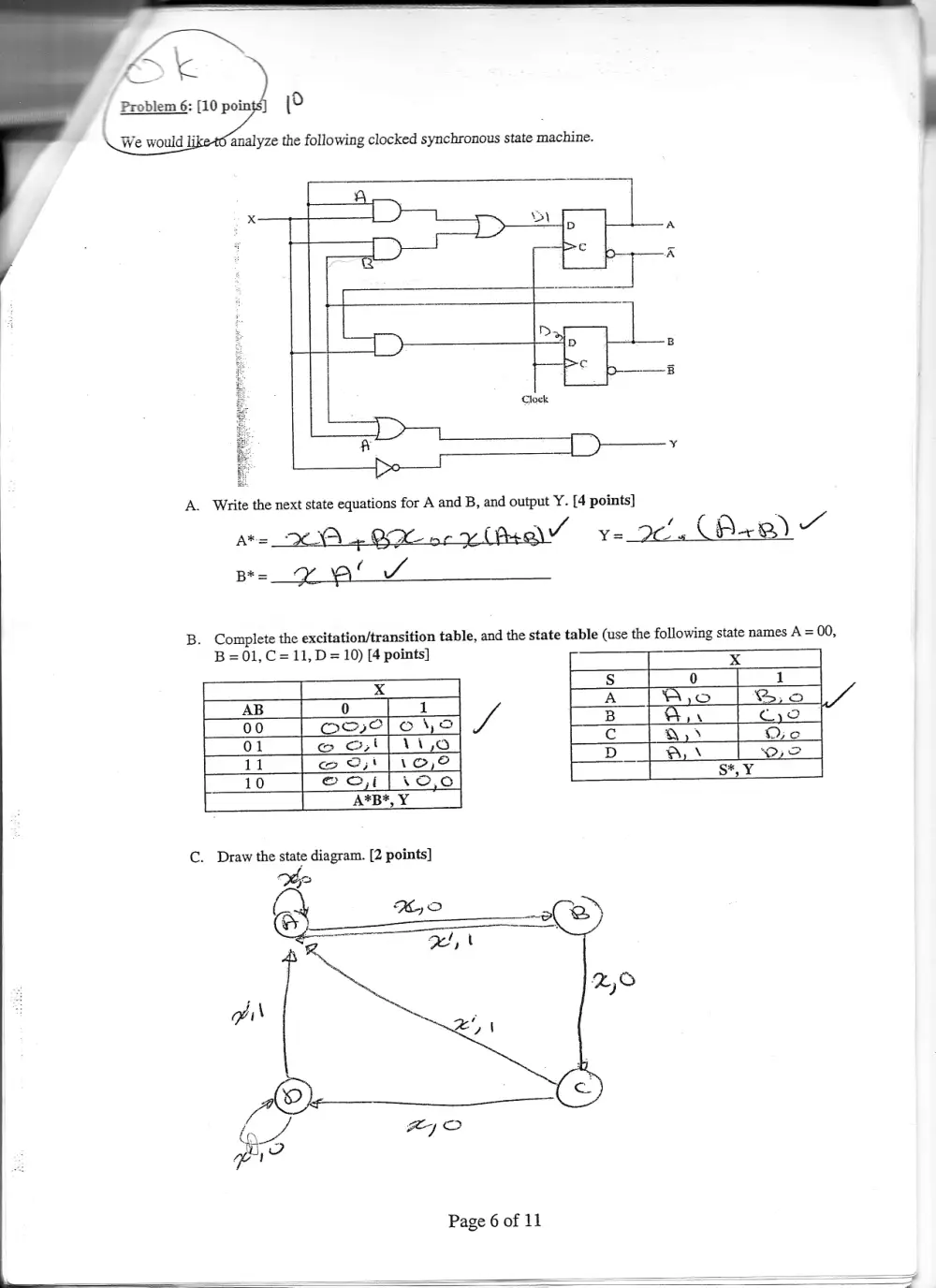
Problem 6: [10 =, \o ‘
\ We would li analyze the following clocked synchronous state machine.
Dd
Ip
= _
t |_ >
TPs er)
Clock
2 a" —_—_[ >—*
A. Write the next state equations for A and B, and output Y. [4 points]
At= CA 4 OR oe PY ¥e van CA) x“
Be= aan WA
B. Complete the excitation/transition table, and the state table (use the following state names A = 00,
B =01, C= 11, D= 10) [4 points] - x
4 5 0 1
ra =
AB 0 I A [Wo |So ly
00 Oove| eye J 2 is G12
01 ce | i1,0 c Q) Die
11 cw Oo; |i o,e dD | A - De
r__10 © 2,1[1o,0 Sy,
A*B*, Y
C. Draw the state diagram. [2 points]
7
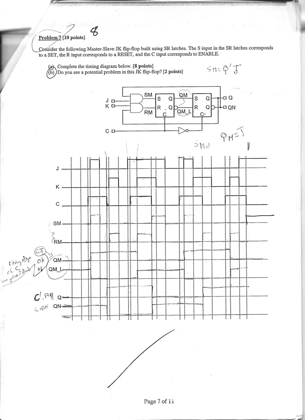
/ Problem 7[10 points}
!
\. Consider the following Master-Slave JK flip-flop built using SR latches. The S input in the SR latches corresponds
to a SET, the R input corresponds to a RESET, and the C input corresponds to ENABLE.
a}, Complete the timing diagram below. [8 points] wo. (
(e)) Do you see a potential problem in this JK flip-flop? [2 points] St 7) 7
cl. os
a wr On} .
Page 7 of 11
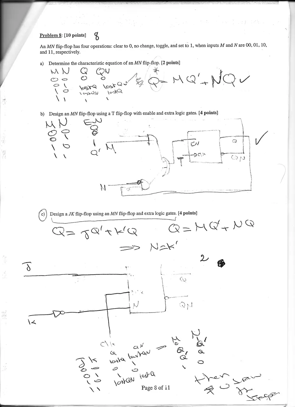
Problem 8: [10 points] %
An MN flip-flop has four operations: clear to 0, no change, toggle, and set to 1, when inputs M and N are 00, 01, 10,
and 11, respectively.
a) Determine the characteristic equation of an MN flip-flop. [2 points]
WN @ @N
() Design a JK flip-flop using an MN flip-flop and extra logic
\
Fcc BEN YS
i ae ?
5
gates. [4 points]
CQ=> toe ~aKQ
—S
Qa r=
¢
=> Nek
pr We bebe bee d
j
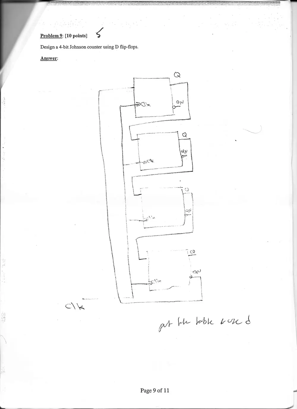
Design a 4-bit Johnson counter using D flip-flops.
Problem 9: [10 points] g
Answer:
Page 9 of 11
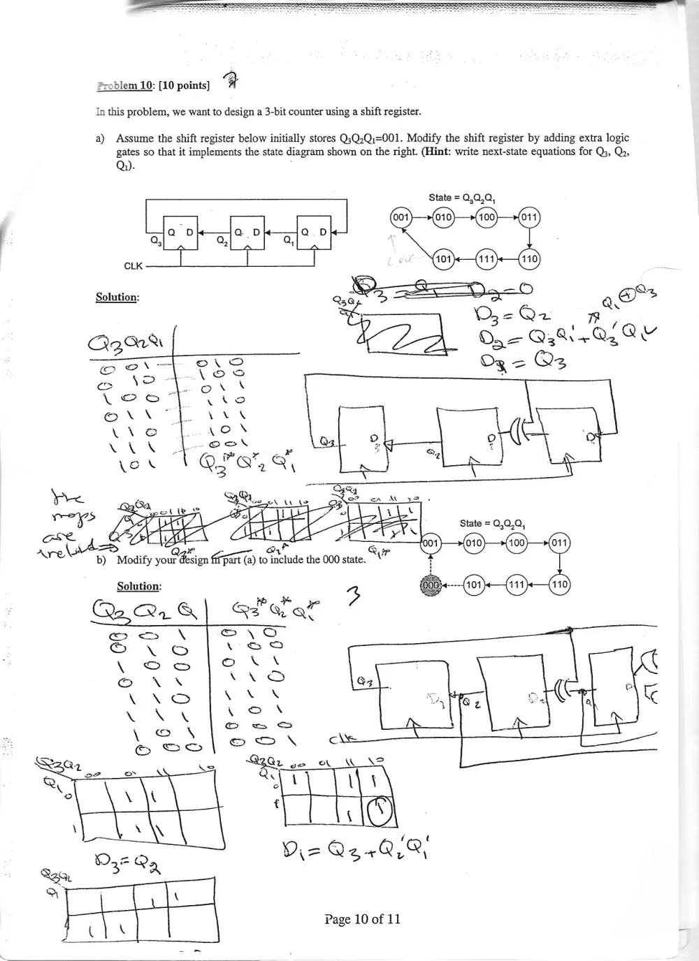
Problem 10: [10 points] i
In this problem, we want to design a 3-bit counter using a shift register.
a) Assume the shift register below initially stores Q;Q.Q:=001. Modify the shift register by adding extra logic
gates so that it implements the state diagram shown on the right. (Hint: write next-state equations for Q3, Qo,
Qi).
State = Q,Q,Q,
beet Se-ee
Solution: % &; aaa ai *
ay a
Qgart So Q: Wn QiQs
= = = Qs
aa
AS
ay cal
b) Modify your Piece kao to include the 000 state.
Solution:
Page 10 of 11
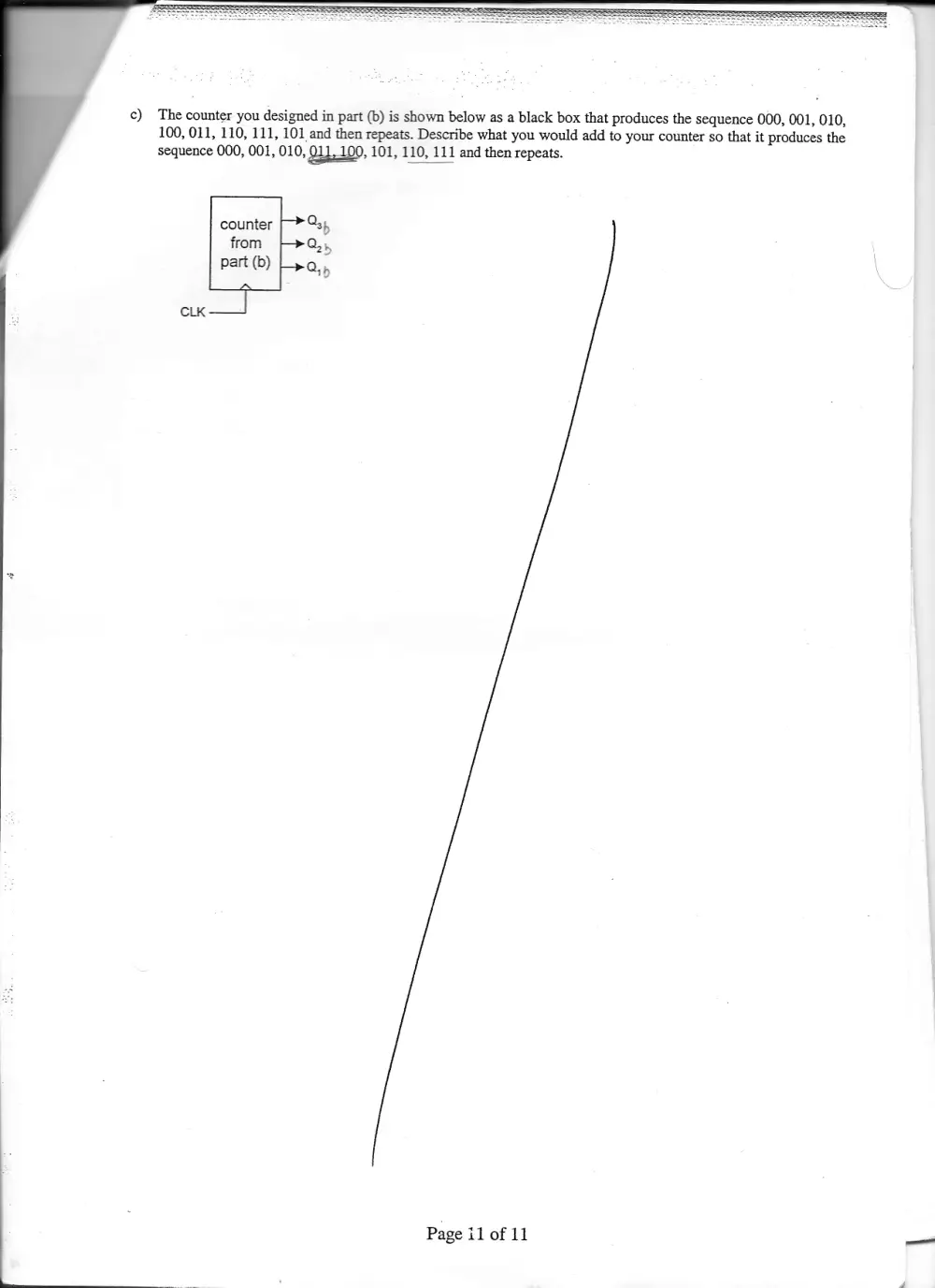
c) The counter you designed in part (b) is shown below as a black box that produces the sequence 000, 001, 010,
100, 011, 110, 111, 101 and then repeats. Describe what you would add to your counter so that it produces the
sequence 000, 001, 010, 011,100, 101, 110, 111 and then repeats.
counter
from -}>Q,,
part (b)
cLK ——
Page il of 11 _