
EECE 433 Chapter 2, Spring 2012
American University of Beirut · Database Systems · 36 pages

Showing the first 10 of 36 pages. Download the PDF to see all of it.
More EECE 433 files
- Problems Chapter 3 · Spring 2012ChapterView
- Chapter 7 · Spring 2012ChapterView
- Chapter 8 · Spring 2012ChapterView
- Problems Chapter 1 & 2 · Spring 2012ChapterView
- Problems Chapter 5 · Spring 2012ChapterView
- Problems Chapter 6 Handout · Spring 2012ChapterView
- Chapter 19 · Spring 2012ChapterView
- Problems Chapter 4 · Spring 2012ChapterView
Show the text of this chapter
Database Management Systems 3ed, R. Ramakrishnan and J. Gehrke
The Entity-Relationship Model
Chapter 2
Database Management Systems 3ed, R. Ramakrishnan and J. Gehrke
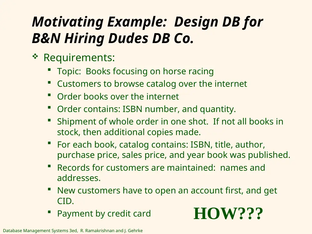
Motivating Example: Design DB for
B&N Hiring Dudes DB Co.
Requirements:
Topic: Books focusing on horse racing
Customers to browse catalog over the internet
Order books over the internet
Order contains: ISBN number, and quantity.
Shipment of whole order in one shot. If not all books in
stock, then additional copies made.
For each book, catalog contains: ISBN, title, author,
purchase price, sales price, and year book was published.
Records for customers are maintained: names and
addresses.
New customers have to open an account first, and get
CID.
Payment by credit card
HOW???
Database Management Systems 3ed, R. Ramakrishnan and J. Gehrke
Outline
Database Design and ER Diagram
Entities, Attributes, & Entity set
Relationships and relationship Set
Additional Features of the ER Model
Conceptual design with the ER Model
Conceptual Design for Large Enterprises
Case Study: Internet Shop
Database Management Systems 3ed, R. Ramakrishnan and J. Gehrke
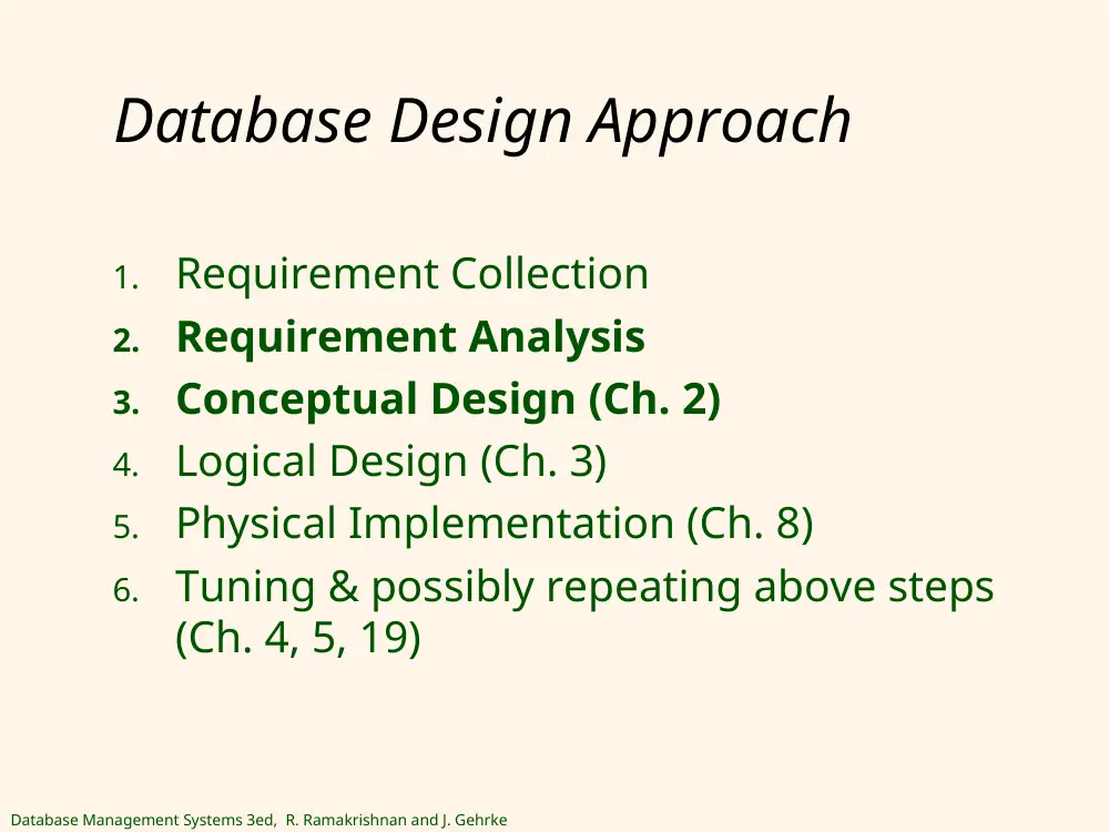
Database Design Approach
1.
Requirement Collection
2.
Requirement Analysis
3.
Conceptual Design (Ch. 2)
4.
Logical Design (Ch. 3)
5.
Physical Implementation (Ch. 8)
6.
Tuning & possibly repeating above steps
(Ch. 4, 5, 19)
Database Management Systems 3ed, R. Ramakrishnan and J. Gehrke
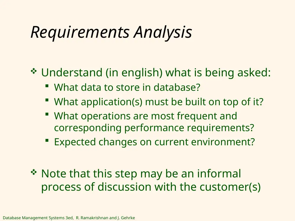
Requirements Analysis
Understand (in english) what is being asked:
What data to store in database?
What application(s) must be built on top of it?
What operations are most frequent and
corresponding performance requirements?
Expected changes on current environment?
Note that this step may be an informal
process of discussion with the customer(s)
Database Management Systems 3ed, R. Ramakrishnan and J. Gehrke
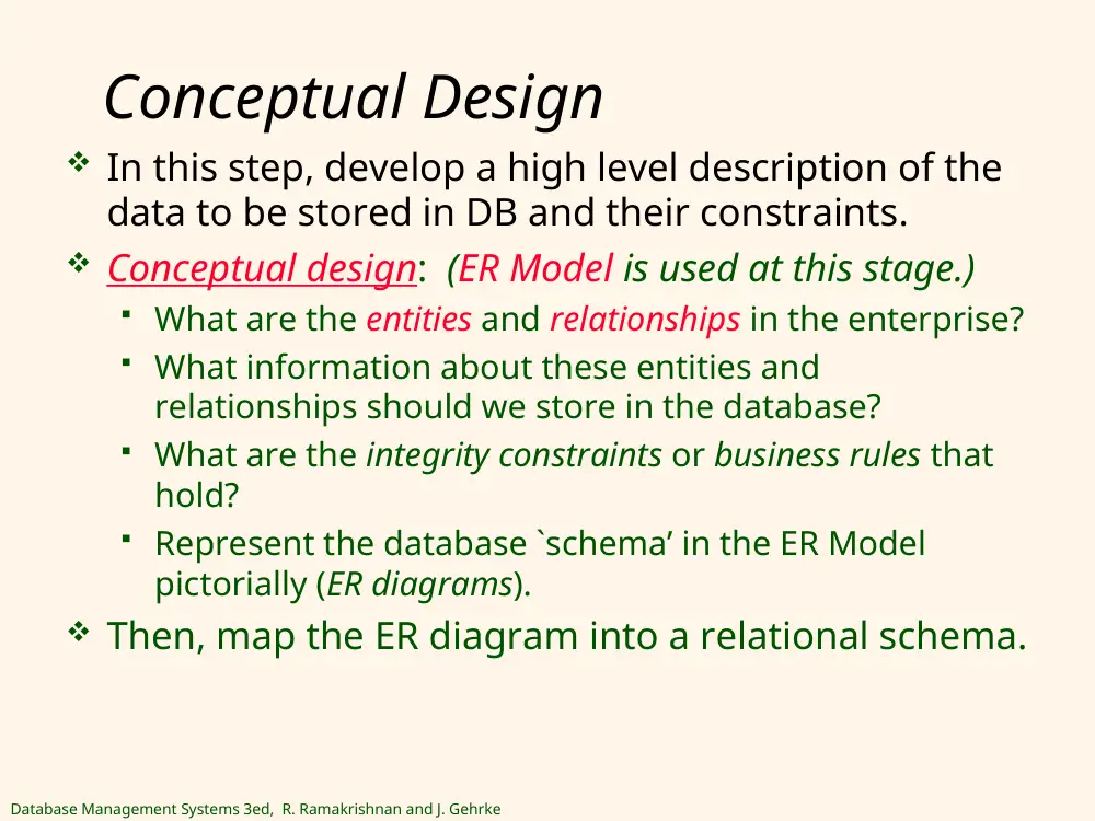
Conceptual Design
In this step, develop a high level description of the
data to be stored in DB and their constraints.
Conceptual design: (ER Model is used at this stage.)
What are the entities and relationships in the enterprise?
What information about these entities and
relationships should we store in the database?
What are the integrity constraints or business rules that
hold?
Represent the database `schema’ in the ER Model
pictorially (ER diagrams).
Then, map the ER diagram into a relational schema.
Database Management Systems 3ed, R. Ramakrishnan and J. Gehrke
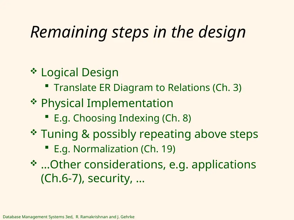
Remaining steps in the design
Logical Design
Translate ER Diagram to Relations (Ch. 3)
Physical Implementation
E.g. Choosing Indexing (Ch. 8)
Tuning & possibly repeating above steps
E.g. Normalization (Ch. 19)
…Other considerations, e.g. applications
(Ch.6-7), security, …
Database Management Systems 3ed, R. Ramakrishnan and J. Gehrke
Outline
Database Design and ER Diagram
Entities, Attributes, & Entity set
Relationships and relationship Set
Additional Features of the ER Model
Conceptual design with the ER Model
Conceptual Design for Large Enterprises
Case Study: Internet Shop
Database Management Systems 3ed, R. Ramakrishnan and J. Gehrke
Entity-Relationship Data Model
(ER)
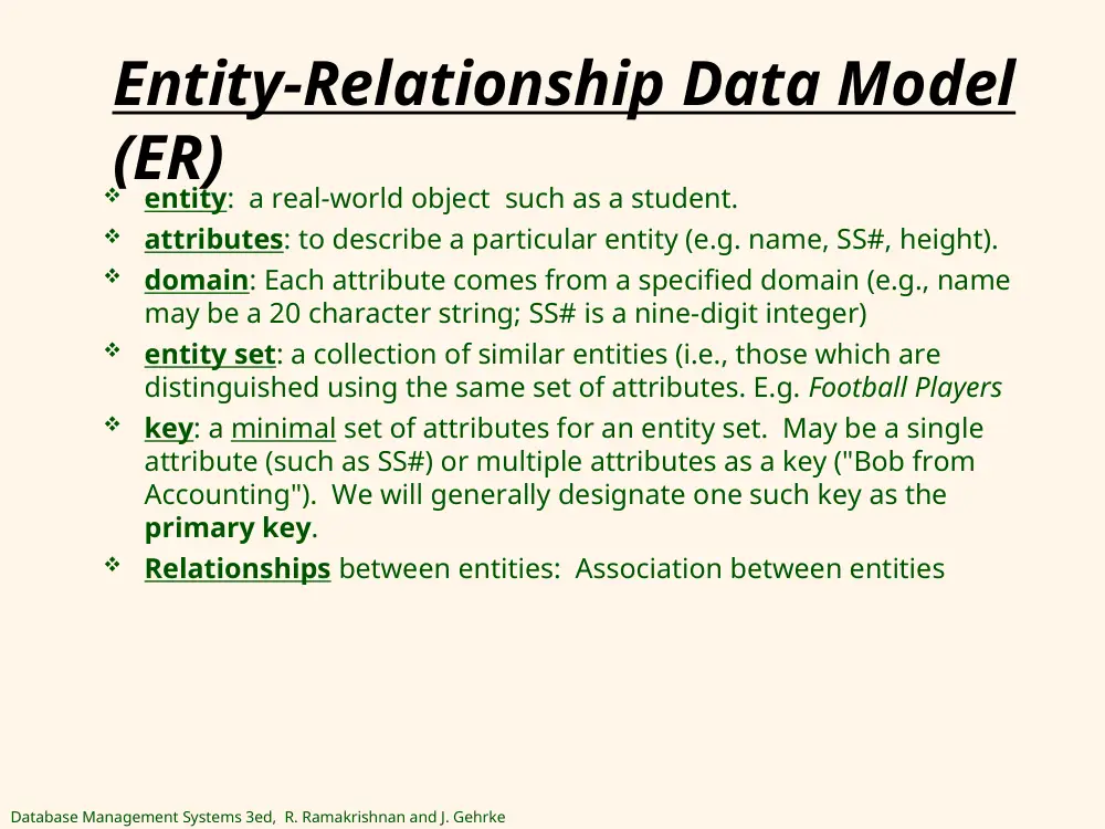
entity: a real-world object such as a student.
attributes: to describe a particular entity (e.g. name, SS#, height).
domain: Each attribute comes from a specified domain (e.g., name
may be a 20 character string; SS# is a nine-digit integer)
entity set: a collection of similar entities (i.e., those which are
distinguished using the same set of attributes. E.g. Football Players
key: a minimal set of attributes for an entity set. May be a single
attribute (such as SS#) or multiple attributes as a key ("Bob from
Accounting"). We will generally designate one such key as the
primary key.
Relationships between entities: Association between entities
Database Management Systems 3ed, R. Ramakrishnan and J. Gehrke
1
ER Diagram - Entities
An entity set is drawn as a rectangle.
Attributes are drawn as ovals.
Attributes which belong to the primary key
are underlined.
Employees
ssn
name
lot
Database Management Systems 3ed, R. Ramakrishnan and J. Gehrke
1
Outline
Database Design and ER Diagram
Entities, Attributes, & Entity set
Relationships and relationship Set
Additional Features of the ER Model
Conceptual design with the ER Model
Conceptual Design for Large Enterprises
Case Study: Internet Shop
Database Management Systems 3ed, R. Ramakrishnan and J. Gehrke
1
Relationships
Relationship: Association among two or more entities.
E.g., Mia works in the Pharmacy department. Ahmad reports to Mia.
Relationship Set: Collection of similar relationships.
An n-ary relationship set R relates n entity sets E1 ... En; each relationship
in R involves entities e1 є E1, ..., en є En. Example above: E1, E2 ==
Employees, Departments. Different types of employee entities working in
different department entities.
Same entity set could participate in different relationship sets, or in
different “roles” in same set. Example: Reports_To
lot
dname
budget
did
since
name
Works_In
Departments
Employees
ssn
Reports_To
lot
name
Employees
subor-
dinate
super-
visor
ssn
Database Management Systems 3ed, R. Ramakrishnan and J. Gehrke
1
ER Model Basics – Relationships
(cont-d)
Descriptive attribute for
relationship to record information
about the relationship.
An instance of a relationship: A
“snapshot” in time of the
relationship set.
since
Works_In
123
456
789
Employees
Works-in
Feb 08
Jan 09
1
2
3
Departments
Database Management Systems 3ed, R. Ramakrishnan and J. Gehrke
1
Types of relationships
Consider
Works_In: An
employee can
work in many
departments; a
dept can have
many employees.
Many-to-Many
1-to-1
1-to Many
Many-to-1
dname
budget
did
since
lot
name
ssn
Works_in
Employees
Departments
One
employee,
one dept
One employee,
works_in many
departments
One employee
works at most
in one dept
Different dept can
have different
employees
Database Management Systems 3ed, R. Ramakrishnan and J. Gehrke
1
Outline
Database Design and ER Diagram
Entities, Attributes, & Entity set
Relationships and relationship Set
Additional Features of the ER Model
Conceptual design with the ER Model
Case Study: Internet Shop
Database Management Systems 3ed, R. Ramakrishnan and J. Gehrke
1
Key Constraint
Assume each dept has at most one manager, according to the key constraint on Manages.
Given a department, we can uniquely identify the Manages relationship in which it appears
Key constraint represents a many (depts) to 1 (employee)
Represented by an arrow
dname
budget
did
since
lot
name
ssn
Manages
Employees
Departments
Database Management Systems 3ed, R. Ramakrishnan and J. Gehrke
1
Participation Constraints
Does every department have a manager?
If so, this is a participation constraint: the participation of
Departments in Manages is said to be total (vs. partial).
• Represented by “bold lines”
• Every did value in Departments table must appear in a
row of the Manages table (with a non-null ssn value!)
lot
name
dname
budget
did
since
name
dname
budget
did
since
Manages
since
Departments
Employees
ssn
Works_In
Also every employee
must be in a dept
Also every dept must
have employees
Database Management Systems 3ed, R. Ramakrishnan and J. Gehrke
1
Dependent “pname” is not unique, unless associated with employee sid
Weak Entities
A weak entity can be identified uniquely only by considering the
primary key of another (owner) entity.
Owner entity set and weak entity set must participate in a one-to-many
relationship set (one owner, many weak entities).
Weak entity set must have total participation in this identifying
relationship set.
Represented by bold boxes around them. Their key is dashed.
lot
name
age
pname
Dependents
Employees
ssn
Policy
cost
Database Management Systems 3ed, R. Ramakrishnan and J. Gehrke
1
Question
How do we represent many to 1, 1 to 1,
and many to many?
budget
did
pid
started_on
pbudget
dname
Departments
Projects
Sponsors
since
Stopped here in MWF section
Database Management Systems 3ed, R. Ramakrishnan and J. Gehrke
2
ISA (`is a’) Hierarchies
Contract_Emps
name
ssn
Employees
lot
hourly_wages
ISA
Hourly_Emps
contractid
hours_worked
• As in C++, or other PLs,
attributes are inherited.
• If we declare A ISA B, every A
entity is also considered to be a
B entity.
Reasons for using ISA:
To add descriptive attributes specific to a subclass.
To identify (specific sub-class) entitities that
participate in a relationship.
Database Management Systems 3ed, R. Ramakrishnan and J. Gehrke
2
Aggregation
Used when we
have to model a
relationship set
involved in another
relationship set.
Aggregation allows
us to treat a
relationship set as
an entity set for
purposes of
participation in
(other)
relationships.
Represented by
dashed box.
Aggregation vs. ternary relationship:
• Monitors is a distinct relationship,
with a descriptive attribute.
• Also, can say that each sponsorship
is monitored by at most one employee.
budget
did
pid
started_on
pbudget
dname
until
Departments
Projects
Sponsors
Employees
Monitors
lot
name
ssn
since
Other good
examples:
OGC vs RPD,
prog mgrs vs
people mgrs
Database Management Systems 3ed, R. Ramakrishnan and J. Gehrke
2
Outline
Database Design and ER Diagram
Entities, Attributes, & Entity set
Relationships and relationship Set
Additional Features of the ER Model
Conceptual design with the ER Model
Case Study: Internet Shop
Database Management Systems 3ed, R. Ramakrishnan and J. Gehrke
2
Conceptual Design Using the ER
Model
Design choices:
Should a concept be modeled as an entity or an
attribute?
Should a concept be modeled as an entity or a
relationship?
Identifying relationships: Binary or ternary?
Aggregation?
Constraints in the ER Model:
A lot of data semantics can (and should) be captured.
But some constraints cannot be captured in ER
diagrams.
Database Management Systems 3ed, R. Ramakrishnan and J. Gehrke
2
Entity vs. Attribute
Should address be an attribute of Employees or an
entity (connected to Employees by a relationship)?
Depends upon the use we want to make of
address information, and the semantics of the
data:
• If we have several addresses per employee,
address must be an entity (since attributes cannot be
set-valued).
• If the structure (city, street, etc.) is important,
e.g., we want to retrieve employees in a given city,
address must be modeled as an entity (since
attribute values are atomic).
Database Management Systems 3ed, R. Ramakrishnan and J. Gehrke
2
Entity vs. Attribute (Contd.)
Works_In4 does not
allow an employee to
work in a department
for two or more periods.
Similar to the problem
of wanting to record
several addresses for an
employee: We want to
record several values
of the descriptive
attributes for each
instance of this
relationship.
Accomplished by
introducing new entity
set, Duration.
name
Employees
ssn
lot
Works_In4
from
to
dname
budget
did
Departments
dname
budget
did
name
Departments
ssn
lot
Employees
Works_In4
Duration
from
to
Database Management Systems 3ed, R. Ramakrishnan and J. Gehrke
2
Entity vs. Relationship (1/2)
Above ER diagram OK if a manager gets a separate
discretionary budget for each dept.
What if a manager gets a (one) discretionary budget that
covers all managed depts?
Redundancy: dbudget stored for each dept managed by manager.
Misleading: Suggests dbudget associated with department-mgr
combination.
Manages2
name
dname
budget
did
Employees
Departments
ssn
lot
dbudget
since
Database Management Systems 3ed, R. Ramakrishnan and J. Gehrke
2
Entity vs. Relationship (2/2)
Fixing the problem:
Create a new entity and assign “dbudget” to the entity rather than the
realtionship.
Eliminates the redundancy
Clear association of “dbudget” to all
dname
budget
did
Departments
Manages2
Employees
name
ssn
lot
since
Managers
dbudget
ISA
How would we change the ER model to represent
one starting date for managing all departments?
Database Management Systems 3ed, R. Ramakrishnan and J. Gehrke
2
Binary vs. Ternary Relationships
If each policy is
owned by just 1
employee, and
each dependent
is tied to the
covering policy,
first diagram is
inaccurate.
What are the
additional
constraints in
the 2nd
diagram?
age
pname
Dependents
Covers
name
Employees
ssn
lot
Policies
policyid
cost
Bad design
Beneficiary
age
pname
Dependents
policyid
cost
Policies
Purchaser
name
Employees
ssn
lot
Better design
Database Management Systems 3ed, R. Ramakrishnan and J. Gehrke
2
Binary vs. Ternary Relationships
(Contd.)
Previous example illustrated a case when two
binary relationships were better than one
ternary relationship.
An example in the other direction: a ternary
relation Contracts relates entity sets Parts,
Departments and Suppliers, and has
descriptive attribute qty. No combination of
binary relationships is an adequate substitute:
S “can-supply” P, D “needs” P, and D “deals-with” S
does not imply that D has agreed to buy P from S.
How do we record qty?
Database Management Systems 3ed, R. Ramakrishnan and J. Gehrke
3
Aggregation vs
Ternary
budget
did
pid
started_on
pbudget
dname
until
Departments
Projects
Sponsors
Employees
Monitors
lot
name
ssn
since
Without “until” attribute, we could have a Ternary
relationship.
But can we say that each sponsorship is
monitored by at most one employee?
Database Management Systems 3ed, R. Ramakrishnan and J. Gehrke
3
Outline
Database Design and ER Diagram
Entities, Attributes, & Entity set
Relationships and relationship Set
Additional Features of the ER Model
Conceptual design with the ER Model
Conceptual Design for Large Enterprises
Case Study: Internet Shop
Database Management Systems 3ed, R. Ramakrishnan and J. Gehrke
3
Case Study: B&N Hiring Dudes DB Co.
Requirements:
Books focusing on horse racing
Customers to browse catalog over the internet
Order books over the internet
Order contains: ISBN number, and quantity.
Shipment of whole order in one shot. If not all books in
stock, then additional copies made.
For each book, catalog contains: ISBN, title, author,
purchase price, sales price, and year book was published.
Records for customers are maintained: names and
addresses.
New customers have to open an account first, and get
CID.
Payment by credit card
Database Management Systems 3ed, R. Ramakrishnan and J. Gehrke
3
Case Study (cont-d): Conceptual
Schema
address
cid
isbn
price
Yr_publish
cname
Customers
Books
Orders
Order_date
Ship_Date
qty
cardnum
Qty_in_stock
Author
title
How to handle?:
1. Same books in same day (qty), 2. diff books in same day (isbn)
3. Same books on different days problem (order = cid/isbn).
Database Management Systems 3ed, R. Ramakrishnan and J. Gehrke
3
Congratulations!!!!
You have just designed your first
Conceptual Database!
Though not optimal yet
Database Management Systems 3ed, R. Ramakrishnan and J. Gehrke
3
Summary of Conceptual Design
Conceptual design follows requirements analysis,
Yields a high-level description of data to be stored
ER model popular for conceptual design
Constructs are expressive, close to the way people think
about their applications.
Basic constructs: entities, relationships, and
attributes (of entities and relationships).
Some additional constructs: weak entities, ISA
hierarchies, and aggregation.
Database Management Systems 3ed, R. Ramakrishnan and J. Gehrke
3
Summary of ER (Contd.)
Several kinds of integrity constraints can be expressed in
the ER model: key constraints, participation constraints, and
overlap/covering constraints for ISA hierarchies
ER design is subjective. There are often many ways to
model a given scenario! Analyzing alternatives can be
tricky, especially for a large enterprise. Common choices
include:
Entity vs. attribute, entity vs. relationship, binary or n-ary
relationship, whether or not to use ISA hierarchies, and whether or
not to use aggregation.
Ensuring good database design: resulting relational
schema should be analyzed and refined further. FD
information and normalization techniques are especially
useful.