
PHYS 205 Chapter 19, Fall 2017
American University of Beirut · Modern Physics for Life Sciences · 42 pages · Mr. Roy Aad


Showing the first 10 of 42 pages. Download the PDF to see all of it.
More PHYS 205 files
Show the text of this chapter
Chapter 19
Electric Potential Energy
and
The Electric Potential
Outline
Outline
1.
Potential Energy
2.
The Electric Potential
Difference
3.
The Electric Potential
Difference Created by Point
Charges
4.
Equipotential Surfaces and
their Relation to the Electric
Field
5.
Capacitors and Dielectrics
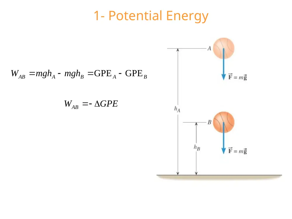
1- Potential Energy
B
A
B
A
AB
mgh
mgh
W
GPE GPE
GPE
WAB
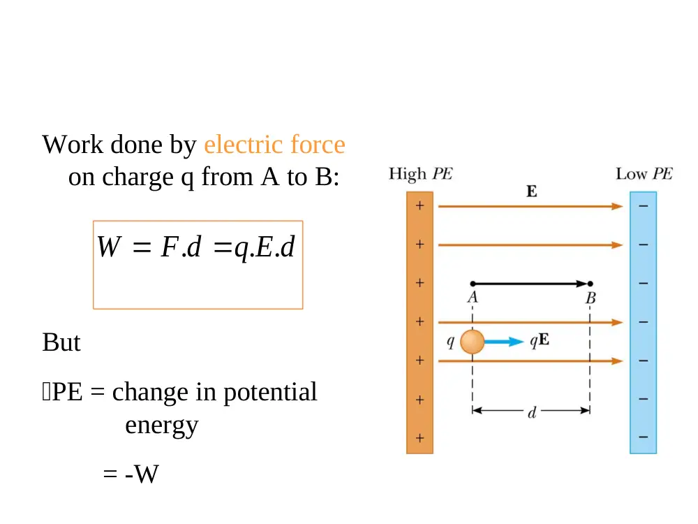
Work done by electric force
on charge q from A to B:
.
. .
W
F d
q E d
But
PE = change in potential
energy
= -W
-
B
A
PE
V
V
V
q
A
B
V
Electric potential at A in Volts (V)
V
Electric potential at B in Volts (V)
Change in potential energy
in Joules (J)
Charge of the particle in Coulombs (C)
PE
q
.
-
-
B
A
J
N m
V
V
Ed
Units Volts
C
C
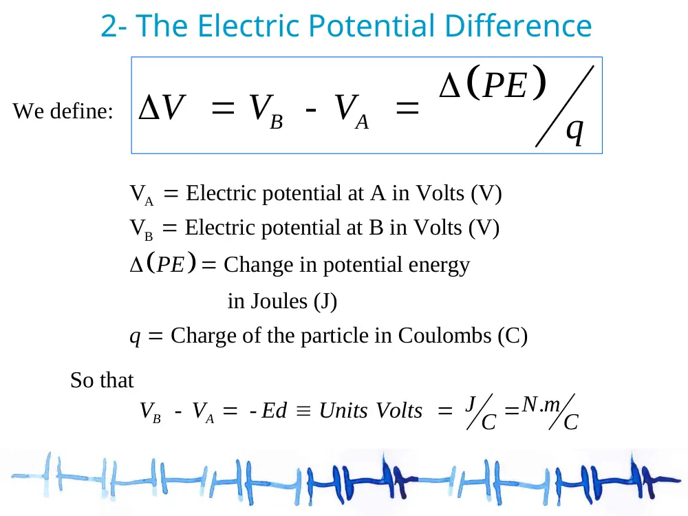
We define:
So that
2- The Electric Potential Difference
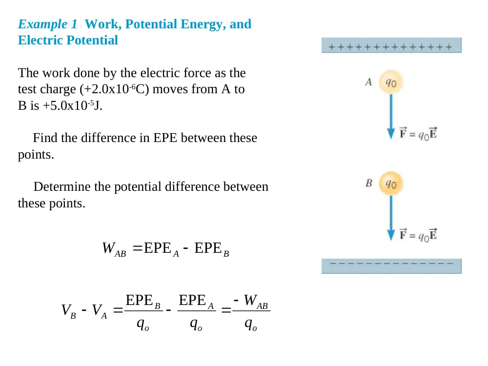
Example 1 Work, Potential Energy, and
Electric Potential
The work done by the electric force as the
test charge (+2.0x10⁻⁶C) moves from A to
B is +5.0x10⁻⁵J.
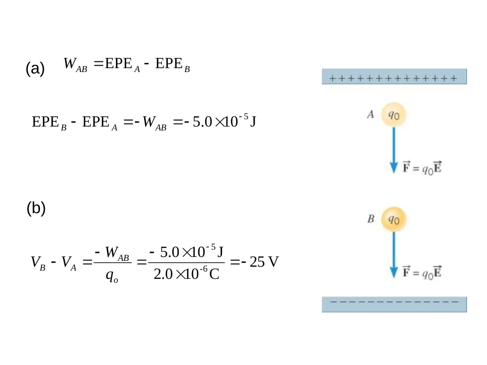
(a)Find the difference in EPE between these
points.
(b)Determine the potential difference between
these points.
B
A
WAB
EPE EPE
o
AB
o
A
o
B
A
B
q
W
q
q
V
V
EPE
EPE
B
A
WAB
EPE EPE
(a)
10 J
0.5
EPE
EPE
5
AB
A
B
W
(b)
25 V
10 C
2.0
10 J
0.5
6
-
5
o
AB
A
B
q
W
V
V
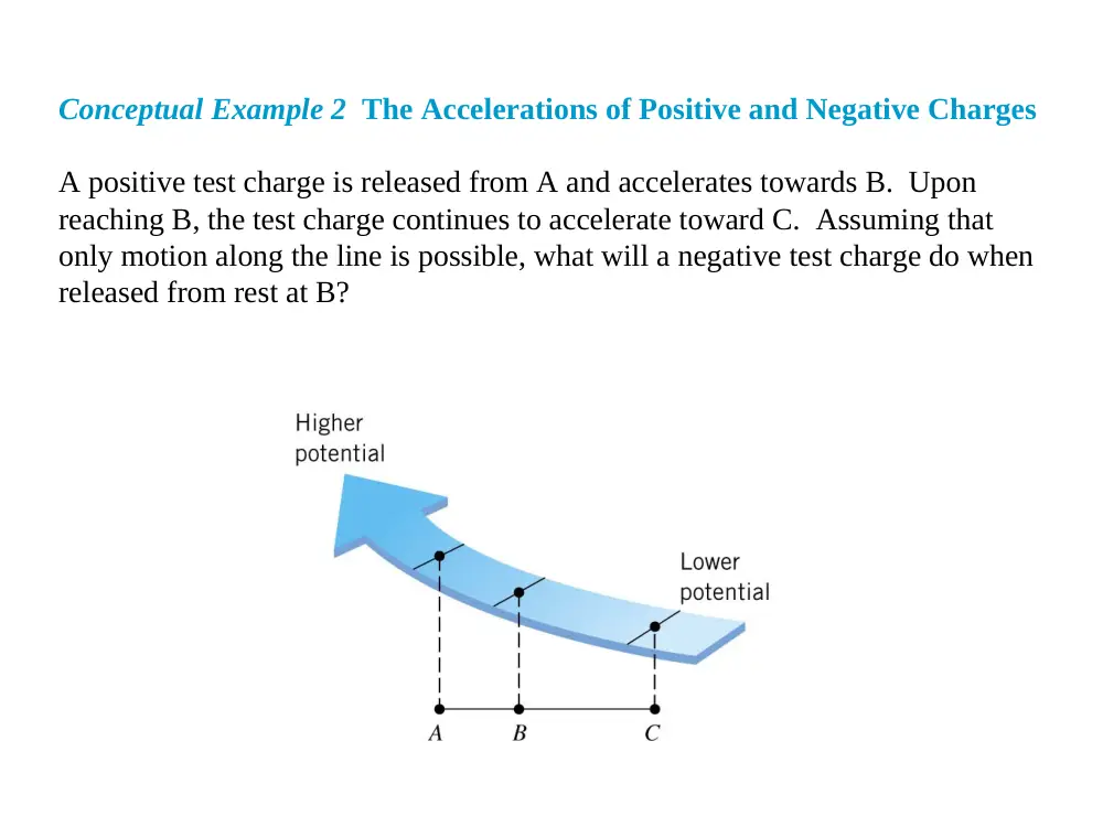
Conceptual Example 2 The Accelerations of Positive and Negative Charges
A positive test charge is released from A and accelerates towards B. Upon
reaching B, the test charge continues to accelerate toward C. Assuming that
only motion along the line is possible, what will a negative test charge do when
released from rest at B?
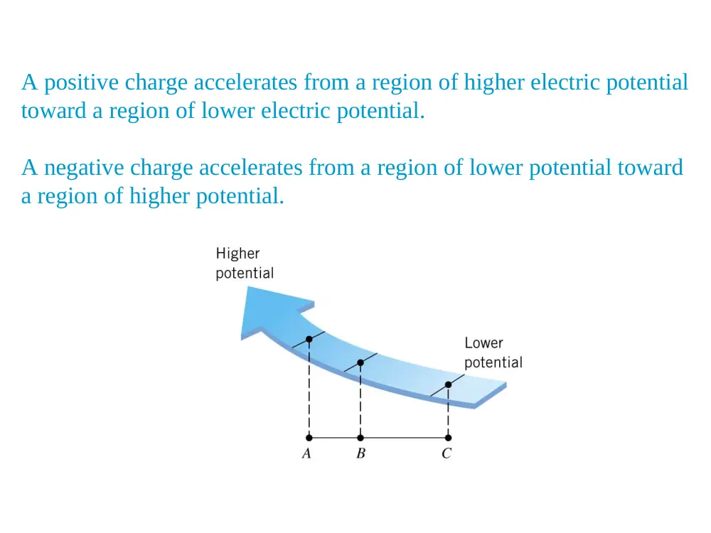
A positive charge accelerates from a region of higher electric potential
toward a region of lower electric potential.
A negative charge accelerates from a region of lower potential toward
a region of higher potential.
Conservation of Energy
EPE
kx
mgh
I
mv
E
2
2
1
2
2
1
2
2
1
Note: the eV electron Volt is defined as the energy
that the electron / proton gains when accelerated
through a potential difference of 1 Volt
Example 4 The Conservation of Energy
A particle has a mass of 1.8x10⁻⁵kg and a charge of +3.0x10⁻⁵C. It is released from
point A and accelerates horizontally until it reaches point B. The only force acting
on the particle is the electric force, and the electric potential at A is 25V greater than
at C. (a) What is the speed of the particle at point B? (b) If the same particle had a
negative charge and were released from point B, what would be its speed at A?
A
A
B
B
EPE
mv
EPE
mv
2
2
1
2
2
1
B
A
A
B
EPE
EPE
mv
mv
2
2
1
2
2
1
B
A
o
A
B
V
q V
mv
mv
2
2
1
2
2
1
B
A
o
B
V
q V
mv
2
2
1
(a)
1.9 m s
10 kg
8.1
10 C 25 V
0.3
2
2
5
5
m
V
q V
v
B
A
o
B
1.9 m s
10 kg
8.1
10 C 25 V
0.3
2
2
5
5
m
V
q V
v
B
A
o
A
(b)
When the electric field is
directed downward, point B
is at a lower potential than
point A
A positive test charge that
moves from A to B loses
electric potential energy
It will gain the same amount
of kinetic energy as it loses
potential energy
0
0
W
PE
W
PE
Electric field
Gravity
Uniform E
-
-
-
0
B
A
B
A
A
B
V
V
Ed
V
V
E
d
V
V
E
Field between two parallel plates
3- The Electric Potential Difference Created
by Point Charges
VA is a scalar quantity.
For several point charges qi ,
A
e
q
V
k r
algebraic sum
TOT
i
i
V
V
The electric potential created at A by a point charge q is:
Consider a charge q0 is brought from infinity to point A
.
.
e
final
initial
A
k q
ke q
V
V
V
V
r
r
0
0
.
.
.
electrical potential energy
of a pair of charges
ek q q
PE
q
V
r
If the charges have the same sign, PE is
positive
Positive work must be done to force the two
charges near one another
The like charges would repel
If the charges have opposite signs, PE is
negative
The Coulomb force does positive work
.
0
e
W
F d
Example 5 The Potential of a Point Charge
Using a zero reference potential at infinity,
determine the amount by which a point charge
of 4.0x10⁻⁸C alters the electric potential at a
spot 1.2m away when the charge is
(a) positive and (b) negative.
V
300
m
2.1
10 C
0.4
C
.8 99 10 N m
8
2
2
9
r
kq
V
(a)
(b)
V 300 V
Example 6 The Total Electric Potential
At locations A and B, find the total electric potential.
240 V
60 m
.0
10 C
0.8
C
99 10 N m
.8
20 m
.0
10 C
0.8
C
.8 99 10 N m
8
2
2
9
8
2
2
9
A
V
0 V
40 m
.0
10 C
0.8
C
99 10 N m
.8
40 m
.0
10 C
0.8
C
.8 99 10 N m
8
2
2
9
8
2
2
9
VB
Potentials and Charged
Conductors
No work is required to move a charge between two
points that are at the same electric potential
- .(
-
)
0
B
A
W
q V
V
Conductors in Equilibrium
E = 0 inside the conductor
The electric field just outside the
conductor is perpendicular to the
surface
The potential is a constant
everywhere on the surface of the
conductor
VA = VB = cst
The potential everywhere inside the
conductor is constant and equal to
its value at the surface
Vinside = Vsurface = cst
4- Equipotential Surfaces and
their relation to the Electric
Field
An equipotential surface is a surface on which all
points have the same electric potential.
Given some initial velocity, no work is required to
move a charge at a constant speed on an
equipotential surface.
The electric field at every point on an
equipotential surface is perpendicular to the
surface
rB
rA
.
e
B
B
k q
V
r
.
e
A
A
k q
V
r
Electric field lines
Equipotential lines
r1
r2
1
2
.
.
TOT
k
q
k q
V
r
r
s
V
E
Example 9 The Electric Field and Potential
Are Related
The plates of the capacitor are separated by
a distance of 0.032 m, and the potential difference
between them is VB-VA=-64V. Between the
two equipotential surfaces shown in color, there
is a potential difference of -3.0V. Find the spacing
between the two colored surfaces.
10 V m
0.2
m
0.032
64 V
3
s
V
E
10 m
5.1
10 V m
0.2
V
0.3
3
3
E
V
s
5- Capacitors and Dielectrics
Most common capacitors is the parallel plate
capacitor.
With A being the area of each plate and d being the
separation between the plates.
The capacitance, C, of a capacitor is defined as:
Q
C
V
Units: Farad (F), 1 F = 1 C / V
Where Q is the charge accumulated on each
plate and V is the potential difference between
the 2 plates.
• The symbol for a
capacitor is
• For a parallel-plate
capacitor whose plates are
separated by air:
o
A
C
d
2
12
2
is the permittivity of free space = 8.85 10
.
1
and Coulomb's constant
4
o
e
o
C
N m
k
Combination of Capacitors
In parallel:
1
2
1
2
1
2
(
)
(
)
but
(
)
TOT
TOT
TOT
TOT
Q
Q
Q
C
V
C
V
Q
C
V
C
C
C
For n capacitors in
parallel:
1
n
eq
i
i
C
C
In series:
1
2
1
2
1
2
and
1
1
1
eq
eq
Q
Q
Q
V
V
V
V
C
C
C
C
C
C
1
1
1
n
i
eq
i
C
C
For n capacitors in series:
Capacitors with Dielectrics
If a dielectric is inserted between the plates of
a capacitor, the capacitance can increase markedly.
Dielectric constant
E
Eo
d
V
E
E
o
A
q
E
o
o
V
d
A
q
o
d
A
C
o
Parallel plate capacitor
filled with a dielectric
Capacitance of Parallel Plate
Capacitor
Conceptual Example 11 The Effect of a Dielectric
When a
Capacitor Has a Constant Charge
An empty capacitor is connected to a battery and charged
up.
The capacitor is then disconnected from the battery, and a
slab
of dielectric material is inserted between the plates. Does
the
voltage across the plates increase, remain the same, or
decrease?
The dielectric becomes polarized.
The presence of the positive charge on the dielectric
effectively reduces some of the negative charge on the
metal
This allows more negative charge on the plates for a given
applied voltage, so Q increases due to the additional flow of
charges.
So the capacitance increases when the dielectric is inserted
between the plates.
Energy Stored in a Capacitor
At t=0, small charges dq are transferred from 1 plate to
another.
Work done by the battery =
.
.
but
dW
V dq
q
q dq
V
dW
C
C
0
0
.
where
.
Q
Q
TOT
batt
q dq
W
dW
Q
V
C
C
2
2
2
.
2
2
2
batt
TOT
CV
q
Q
W
C
C
2
.
energy stored in a capacitor
2
CVbatt
2
2
1
Energy
CV
2
2
1
Energy
Ed
d
o A
2
2
1
Volume
Energy
Energy density
o E
Volume Ad