
PHYS 205 Chapter 22, Fall 2017
American University of Beirut · Modern Physics for Life Sciences · 29 pages · Mr. Roy Aad
Showing the first 10 of 29 pages. Download the PDF to see all of it.
More PHYS 205 files
Show the text of this chapter
Chapter 23
Alternating Current Circuits
Outline
1.
Capacitors and
Capacitive Reactance
2.
Inductors and Inductive
Reactance
3.
Circuits Containing
Resistance, Capacitance,
and Inductance
4.
Resonance in Electric
Circuits
5.
Semiconductor Devices
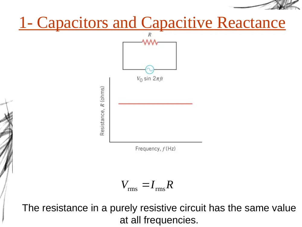
1- Capacitors and Capacitive Reactance
R
I
V
rms
rms
The resistance in a purely resistive circuit has the same value
at all frequencies.
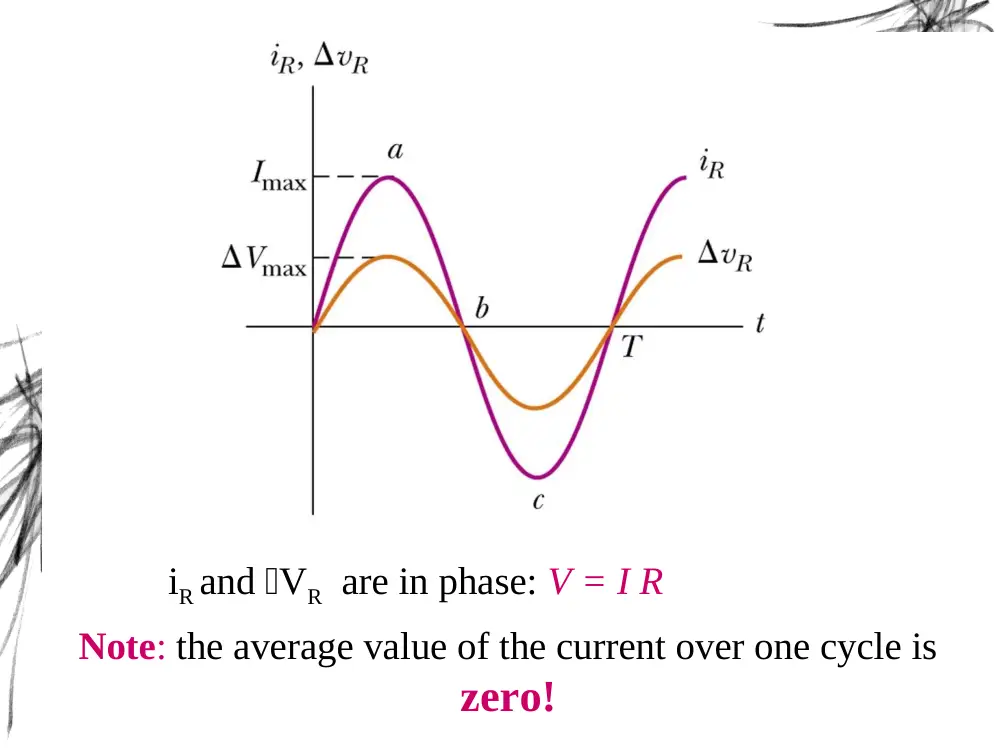
Note: the average value of the current over one cycle is
zero!
iR and VR are in phase: V = I R
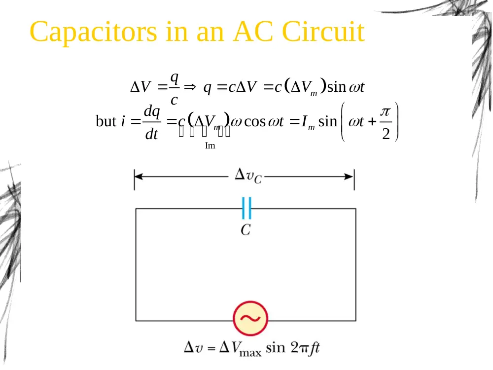
Capacitors in an AC Circuit
sin
m
q
V
q
c V
c
V
t
c
Im
but
cos
sin
2
m
m
dq
i
c
V
t
I
t
dt
m sin
V
V
t
sin
2
m
i
I
t
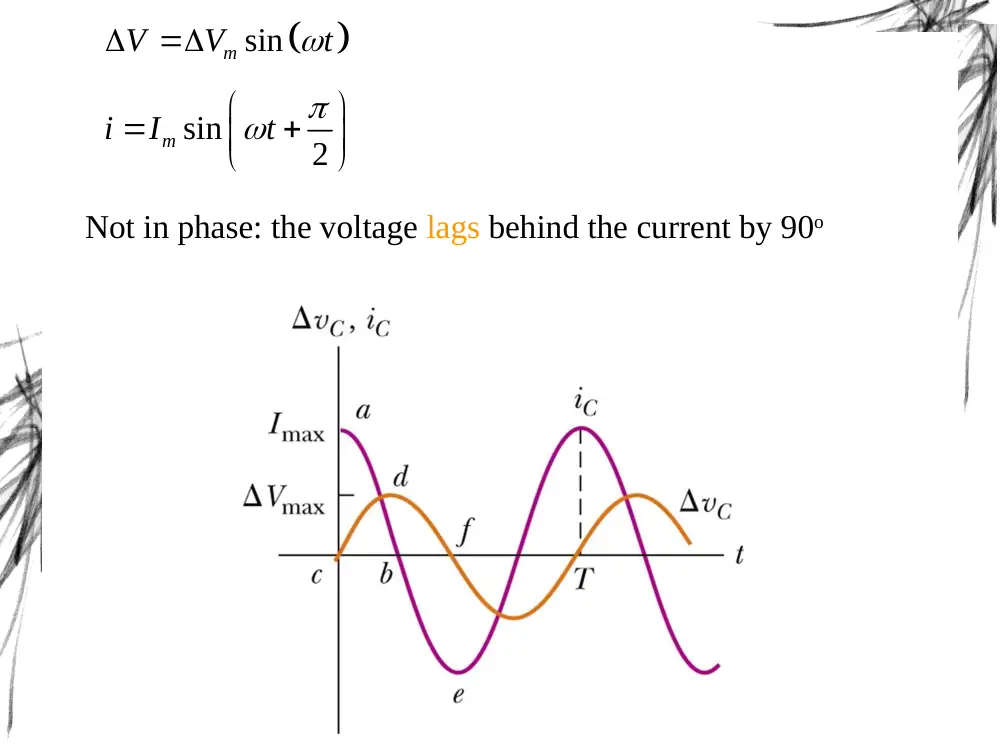
Not in phase: the voltage lags behind the current by 90o
1
1
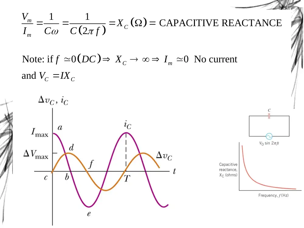
CAPACITIVE REACTANCE
2
m
C
m
V
X
I
C
C
f
Note: if
0
0 No current
and
C
m
C
C
f
DC
X
I
V
IX
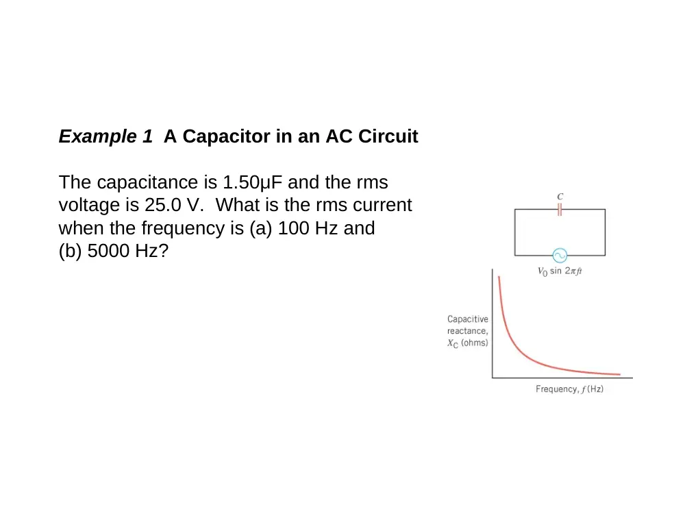
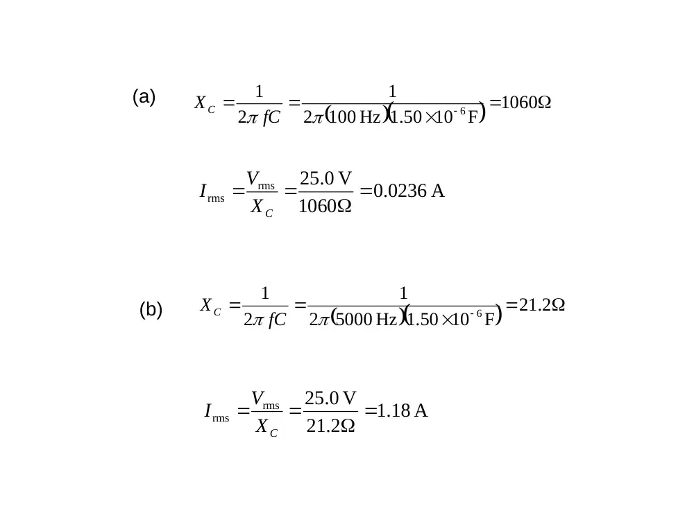
Example 1 A Capacitor in an AC Circuit
The capacitance is 1.50μF and the rms
voltage is 25.0 V. What is the rms current
when the frequency is (a) 100 Hz and
(b) 5000 Hz?
.0 0236 A
1060
0. V
25
rms
rms
XC
V
I
1060
F
.1 50 10
100 Hz
2
1
2
1
6
fC
X C
(a)
(b)
21 2.
F
.1 50 10
5000 Hz
2
1
2
1
6
fC
X C
.1 18 A
21.2
0. V
25
rms
rms
XC
V
I
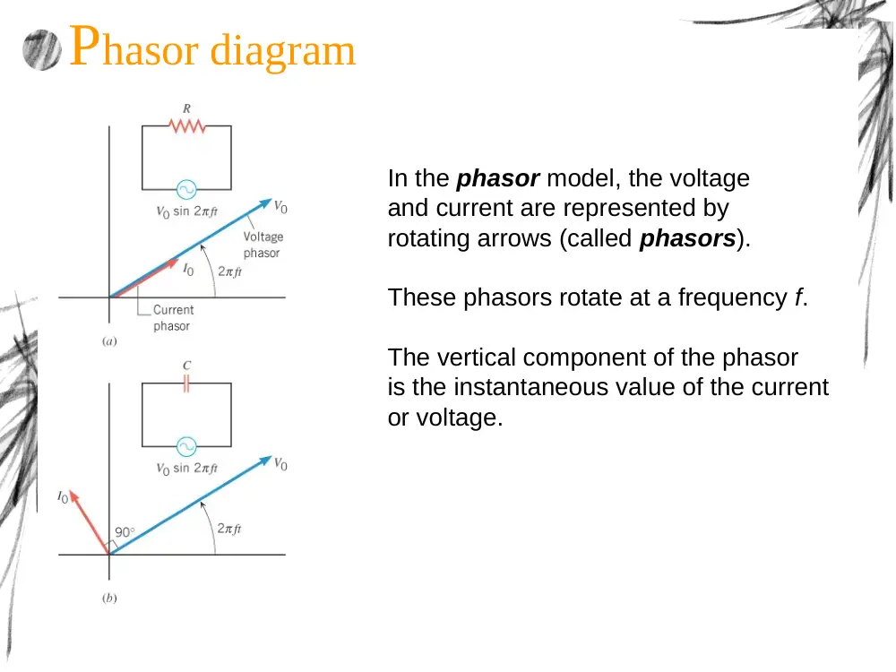
In the phasor model, the voltage
and current are represented by
rotating arrows (called phasors).
These phasors rotate at a frequency f.
The vertical component of the phasor
is the instantaneous value of the current
or voltage.
Phasor diagram
2- Inductors in an AC Circuit
0
L
di
V
L dt
sin
2
Vm
i
t
L
sin
.
cos
m
m
V
V
i
t dt
t
L
L
sin
L
m
di
V
L
V
t
dt
sin
L
m
V
V
t
sin
2
Vm
i
t
L
Not in phase: the voltage leads the current by 90o
INDUCTIVE REACTANCE
Also
m
m
m
L
m
L
V
V
I
X
L
L
I
V
X I
Phasor diagram
3- Circuits containing resistance,
capacitance, and inductance
= I XL
= I XC
= I R
Phasor diagram
Direction of
Current
Phasor diagram
2
2
TOT
L
C
R
V
V
V
V
tan
L
C
R
V
V
V
2
2
L
C
V
I
R
X
X
tan
L
C
X
X
R
2
2
Total impedance of RLC circuit
TOT
L
C
Z
R
X
X
With:
XL
L
1
XC
C
1
ZC
C
ZL
L
ZR
R
Sum
Leads i by 90o
In phase with i
Lags behind i by
90o
Conceptual Example 4 The Limiting Behavior of
Capacitors and Inductors
The rms voltage of the generator is the same in each
case. The values of the resistance, capacitance, and
inductance are the same. The frequency of the ac
generator is very near zero.
In which circuit does the generator supply more rms
current?
Equivalent to
Power in an AC Circuit
After 1 cycle, capacitors and inductors do not
dissipate energy. They actually store energy
during the first half cycle and the same amount
during the second half cycle.
The only power lost is across the resistor:
but
cos
av
R
R
P
IV
V
V
av
P is maximal for cos
1 ;
0
cos
cos
power factor
av
P
IV
4- Resonance in electric circuits
LC
2
1
ƒo
2
2
L
C
V
V
I
Z
R
X
X
For
L
C
X
X
1
L
C
0
0
1
1
and
2
f
LC
LC
Resonant frequency
5- Semiconductor devices
Semiconductor devices such as diodes and transistors are widely
used in modern electronics.
The semiconducting materials (silicon and
germanium) used to make diodes and
transistors are doped by adding small
amounts of an impurity element.
n type and p type
semiconductors
At the junction between the n and p materials, mobile electrons and
holes combine and create positive and negative charge layers.
The semiconductor diode
There is an appreciable current through the diode when the
diode is forward biased.
Under a reverse bias, there is almost no current through the
diode.