
PHYS 205 Chapter 20, Fall 2017
American University of Beirut · Modern Physics for Life Sciences · 45 pages · Mr. Roy Aad




Showing the first 10 of 45 pages. Download the PDF to see all of it.
More PHYS 205 files
Show the text of this chapter
Chapter 20
Electric Circuits
Outline
1.
Electromotive Force and Current
2.
Ohm’s Law
3.
Resistance and Resistivity
4.
Electric Power
5.
Alternating current
6.
Series Wiring
7.
Parallel Wiring
8.
Circuits Wired Partially in Parallel and Partially in
Series
9.
Internal Resistance
10.
Kirchhoff’s Rules
11.
The Measurement of Current and Voltage
12.
Capacitors in Series and in Parallel
13.
RC Circuits
14.
Safety and the Physiological Effects of Current
1- Electromotive Force and Current
Within a battery, a chemical reaction occurs that transfers electrons
from one terminal to another terminal.
The maximum potential difference across the terminals is called the
electromotive force (emf).
I is the amount of charges passing through A per unit time:
C
in A
Ampere (
)
A
Q
I
t
2
Current density:
(
)
I
A
J
A
m
Current and Drift Speed
-
drift speed = speed of e in a conductor
dv
. .
.
d
Q
I
n q v A
t
. .
.
. .
. charge in gray portion
d
Q
n A
x q
n Av
t q
n = number of mobile charges
unit volume
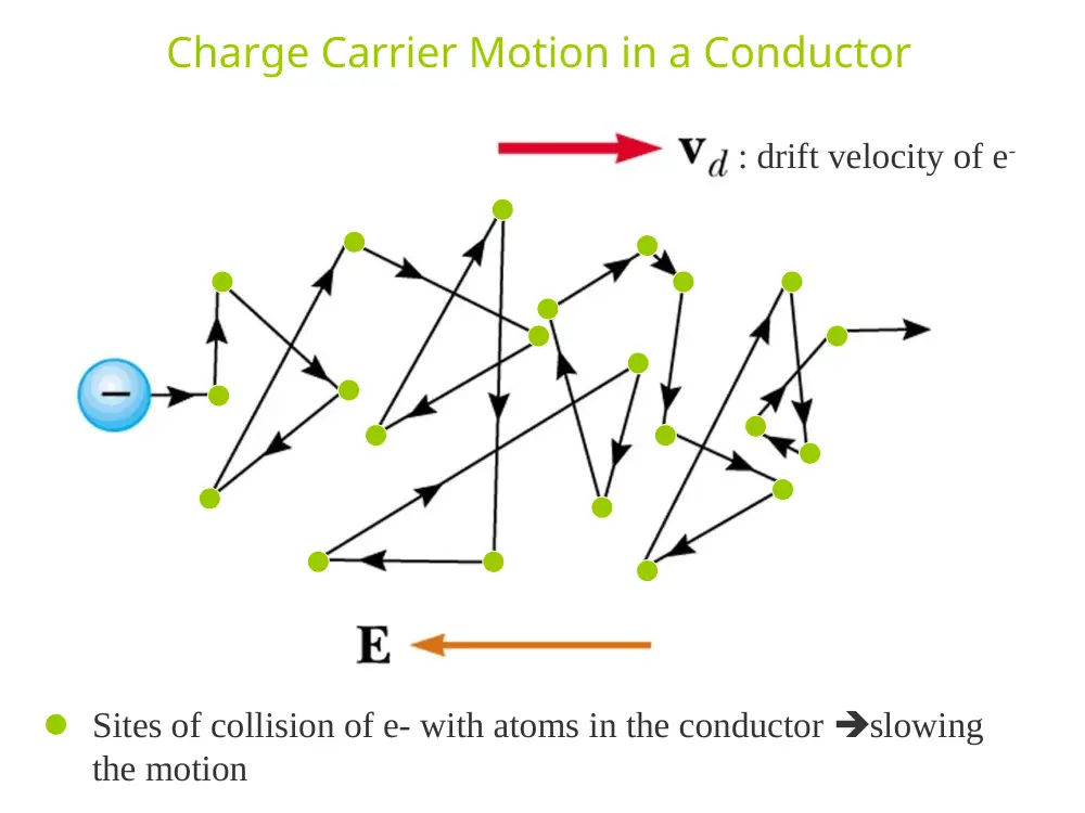
Charge Carrier Motion in a Conductor
: drift velocity of e-
Sites of collision of e- with atoms in the conductor slowing
the motion
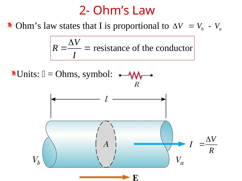
2- Ohm’s Law
Ohm’s law states that I is proportional to
I
V
R
resistance of the conductor
V
R
I
V
R
b -
a
V
V
V
Units: = Ohms, symbol:
Ohmic material
V
I R
V
I R
Non-Ohmic material
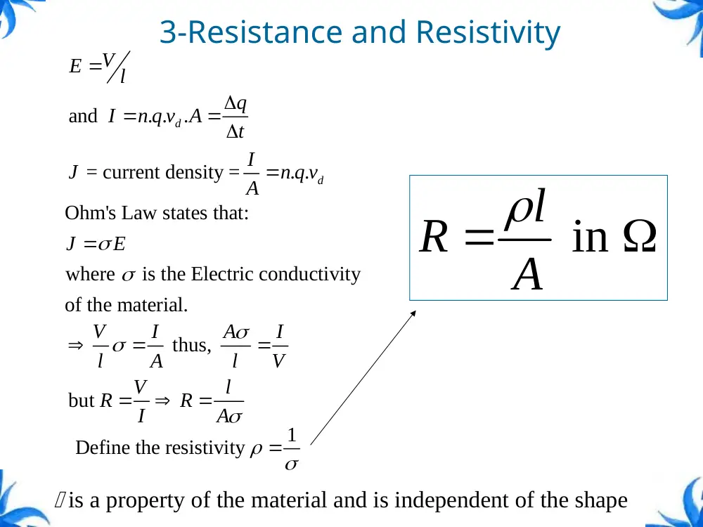
3-Resistance and Resistivity
A
L
R
and
. .
.
d
V
E
l
q
I
n q v A
t
= current density =
. . d
I
J
n q v
A
Ohm's Law states that:
where
is the Electric conductivity
of the material.
J
E
thus,
but
V
I
A
I
l
A
l
V
V
l
R
R
I
A
1
Define the resistivity
l in
R
A
is a property of the material and is independent of the shape
Temperature Variation of
Resistivity
The resistivity of a metal depends on temperature.
0
0
1
T
T
0
0
1
R
R
T
T
Where:
is the resistivity at temperature T
0 is the resistivity at temperature T0
is the temperature coefficient of resistivity
Superconductors
A class of materials and
compounds whose resistances fall
to virtually zero below a certain
temperature, TC, , the critical
temperature.
The critical temperatures of:
Al is 1.2 K, He liquid is 4.2 K.
YBa2Cu3O7 is 90 K, N2 liquid is
80 K.
Once a current is set up in a
superconductor, it persists without
any applied voltage, since R = 0
4- Electrical Power
Consider the motion of a charge Q,
Ground: reference for voltage
From A to B, Q gains in
potential energy:
From C to D, Q loses in
potential energy because of
the heating of the resistor
.
Epot
q
V
The rate at which the energy is lost when going
through the resistor is:
Q
V
I V
Power
t
2
2
(
V )
P
I R
R
3
6
1
10
3600
3.6 10
1 Kilowatt-hour
kWh
W
s
J
From Ohm’s Law, alternate forms of power are:
5- Alternating Current
In an AC circuit, the charge flow reverses direction periodically.
ft
V
V
o
sin 2
In circuits that contain only resistance, the current reverses direction
each time the polarity of the generator reverses.
ft
I
ft
R
V
R
V
I
o
o
sin 2
sin 2
peak
current
ft
I V
IV
P
o o
sin 2 2
ft
I
I
o
sin 2
ft
V
V
o
sin 2
rms rms
2
2
2
V
I
V
I
I V
P
o
o
o o
Root-mean-square (rms)
current and voltage
R
I
V
rms
rms
VrmsIrms
P
R
I
P
2
rms
R
V
P
2
rms
6- Series Wiring
Resistors are connected end to end.
Potentials add
ΔV = IR1 + IR2 = I (R1+R2)
Consequence of Conservation of Energy
The equivalent resistance, Requ , has the effect on the circuit as the
original combination of resistors
Requ = R1 + R2
Example 8 Resistors in a Series Circuit
A 6.00 Ω resistor and a 3.00 Ω resistor are connected in series with
a 12.0 V battery. Assuming the battery contributes no resistance to
the circuit, find (a) the current, (b) the power dissipated in each resistor,
and (c) the total power delivered to the resistors by the battery.
(a)
(b)
(c)
.9 00
.3 00
.6 00
RS
.1 33 A
00
.9
12 0. V
RS
V
I
10 6. W
.6 00
33 A
.1
2
2
I R
P
.5 31 W
.3 00
33 A
.1
2
2
I R
P
15 9. W
.5 31 W
10 6. W
P
7 – Parallel Wiring
Resistors are connected across each other.
Equivalent resistance replaces the two
original resistances
V = I1R1 = I2 R2 = Req I
I = I1 +I2
ΔV/Req = ΔV/R1 + ΔV/R2
1
2
1
1
1
Requ
R
R
8 – Circuits Wired Partially in
Parallel and Partially in Series
The schematic shows the internal resistance, r
The terminal voltage,
ΔV = Vb-Va
ΔV = ε – Ir
For the entire circuit:
ε = IR + Ir
R = load resistor
9- Internal resistance
10- Kirchhoff’s Rules
There are ways in which resistors can be
connected so that the circuits formed cannot
be reduced to a single equivalent resistor
Two rules, called Kirchhoff’s Rules can be
used to solve the problem.
Statement of Kirchhoff’s Rules
Junction Rule
The sum of the currents entering any junction
must equal the sum of the currents leaving that
junction
A statement of Conservation of Charge
Loop Rule
The sum of the potential differences across all the
elements around any closed circuit loop must be
zero
A statement of Conservation of Energy
I1 = I2 + I3
From Conservation of
Charge
Diagram b shows a
mechanical analog
The junction
rule:
Potential difference across R and ε
Junction Equations from
Kirchhoff’s Rules
In general, the number of times the junction rule
can be used is one fewer than the number of
junction points in the circuit
The loop rule can be used as often as needed so
long as a new circuit element (resistor or battery)
or a new current appears in each new equation
You need as many independent equations as you
have unknowns
Junction rule at C:
I1 +I2 = I3
Loop rule:
Loop abcda:
10V - (6)I1 - (2)I3 = 0
Loop befcb:
-14V + (6)I1 - 10V – (4)I2 = 0
So that I1=2 A; I2=-3 A & I3=-1 A
When a current is found to have a negative value, its direction on
the circuit diagram should be reversed.
Example 14 Using Kirchhoff’s Loop Rule
Determine the current in the circuit.
potential rises
drops
potential
24 V
0.8
V
0.6
12
I
I
I .0 90 A
Determine the current through the car battery, the headlights, and
the alternator
11- The Measurement of Current and
Voltage
An ammeter must be inserted into
a circuit so that the current passes
directly through it.
To measure the voltage between two points
in a circuit, a voltmeter is connected between
the points.
12- Capacitors in Series and
in Parallel
Parallel capacitors
3
2
1
C
C
C
CP
C V
C
C V
C V
q
q
q
2
1
2
1
2
1
2
1
2
1
2
1
1
1
C
q C
C
q
C
q
V
V
V
Series capacitors
3
2
1
1
1
1
1
C
C
C
CS
13- RC Circuits
When the switch is closed, a current is induced
and charge accumulate on the capacitor.
The capacitor continues to charge until it
reaches its maximum charge (Q = Cε) and
the current stops.
Once the capacitor is fully charged, the
current in the circuit is zero.
• Kirchhoff’s rule across the loop:
ε-Vc-iR = ε -(q/C)-R(dq/dt) = 0
Charging a Capacitor in an RC
Circuit
The charge on the capacitor
varies with time
q = Q(1 – e-t/RC)
The time constant, = RC
The time constant represents
the time required for the
charge to increase from zero to
63.2% of its maximum
Discharge
When the switch is closed, the capacitor discharges until Q = 0
and the current stops.
Kirchhoff’s rule across loop: Vc-iR = (q/C)-R(dq/dt) = 0
Discharging Capacitor in an RC
Circuit
When a charged capacitor
is placed in the circuit, it
can be discharged
q = Qe-t/RC
The charge decreases
exponentially
At t = = RC, the charge
decreases to 0.368 Qmax
In other words, in one time
constant, the capacitor loses
63.2% of its initial charge
14- Safety and Physiological Effects
of Current
To reduce the danger inherent in using circuits, proper electrical grounding
is necessary.